Article

Greenhouse Desalination by Humidification–Dehumidification Using a Novel Green Packing Material

1
College of Engineering, Northern Border University, Arar 73222, Saudi Arabia
2
Civil Engineering Laboratory, National Engineers School of Tunis (ENIT), University of Tunis El Manar, Tunis 1002, Tunisia
3
College of Science, Northern Border University, Arar 73222, Saudi Arabia
4
College of Engineering and Technology, Arab Academy for Science, Technology and Maritime Transport (AASTMT), Alexandria 1029, Egypt
5
City for Scientific Research and Technological Applications, New Borg El Arab City, Alexandria 21934, Egypt
*
Author to whom correspondence should be addressed.
Water 2022, 14(6), 869; https://doi.org/10.3390/w14060869
Submission received: 12 January 2022 / Revised: 19 February 2022 / Accepted: 25 February 2022 / Published: 10 March 2022
(This article belongs to the Topic Water Reclamation and Reuse)

Abstract

:
Humidification–dehumidification (HD) is a non-traditional desalination process in which water evaporates from a saline liquid stream and the vapour condenses into purified water. In nature, seawater is heated by solar radiation and evaporates from the air that moistens it. This is known as the rainy cycle. The artificial version of this cycle is called the HD desalination cycle. The latter has received a lot of attention in recent years, and many researchers have studied the complexities of the technology. In the present work, experimental work with a simple configuration was developed and built, consisting of a humidification column followed by a condenser, in which the humidified air is dehumidified to produce fresh water. A novel and unique packaging material was used in the humidifier, consisting of a cellulose plant grown on the banks of the River Nile. In all previous work, the main problem was the type of packaging material that could ensure intimate contact and uniformity between aqueous flow and airflow. Consequently, this new filler material proved extremely suitable in terms of hydrophilicity and interconnectivity. Several variables, including the packing mass of each stage, the number of stages, the flow of air and saltwater, the concentration of saltwater, and the inlet temperature of saltwater and condensation temperature, were examined to determine their influence on the production of fresh water and its salinity. The best results arrived at in this study were wet packing conditions, 0.5 m/s air flowrate, 26 g packing for each of the 6-stage columns, and 500 mL/min water flow rate at 70 °C. It was found that this present setup, which can be coupled with solar heating to make the greenhouse desalination process cost-effective, could produce a high production of fresh water and be competitive compared with other commercial applications.

1. Introduction

More than a billion people worldwide have no access to clean water [1]. The vast majority of these people live in low-income communities. Desalination technologies can remove all contaminants, including almost all dissolved ions, microorganisms, etc. For example, reverse osmosis (RO) removes even the smallest of contaminants. Furthermore, it is well known that thermal desalination technologies remove all contaminants (creating deionized water). However, the challenges in implementing these technologies are to cost-effectively provide them at the community level (10–100 m3/day) and provide them relatively maintenance-free. HD desalination offers small-scale desalination technology that meets these challenges.
HD desalination is a non-traditional desalination process in which water is evaporated from a salty liquid stream to a carrier gas stream and then the vapour is condensed into purified water. In the rain cycle, nature employs air as a carrier gas to desalinate saltwater. Seawater is heated (by sunshine) and evaporates into the air above to wet it during the rainy cycle. The humidified air then rises and produces clouds. Finally, the clouds are “dehumidified” in the form of rain, and what falls on the ground can be collected for human consumption. The HD desalination cycle is an artificial version of this cycle. Figure 1 depicts the HD cycle in its most basic form. The cycle is divided into three subsystems: (a) an air and/or brine heater (just one depicted in the picture), which can be driven by solar energy, heat, geothermal energy, or a combination of these; (b) the humidifier or vaporizer; and (c) the dehumidifier or condenser.
The HD cycle has received much interest in recent years, and several academics have looked at the complexities of this technology. It is worth noting that simple solar is still the precursor technology of the HD cycle. Several researchers [3,4,5,6,7,8,9,10,11,12] have examined many works on solar anchors. It is important to understand the limitations of the solar standstill concept.
There are three major groups of HD systems. One classification is based on the energy source, such as solar, heating, geothermal, or hybrid systems. This categorization highlights a hopeful aspect of the HD concept: the possibility of obtaining water with less energy, particularly from industrial waste heat or renewable resources, such as solar energy or biomass. The second classification is based on the cycle configuration (Figure 2). A closed-water open-air cycle (CWOA) is a cycle in which ambient air is pulled into the humidifier, heated, and humidified, and then transferred to the dehumidifier, where it is partially dehumidified and drained in an open circuit to form a closed circuit. Between the humidifier and the dehumidifier, air flows in a closed circuit. The brine is recirculated in this cycle until the necessary recovery is attained. In these systems, mechanical or natural convection fans can circulate the air, and a pump is often utilized to circulate the feed water. It is critical to understand the respective technological benefits of each of these circuits and to select the design that maximizes efficiency and reduces water production costs. The third type of HD system is determined by the type of heating utilized (water or air). The fluid being heated has a significant impact on system performance.
Water’s capability for long-term sustainability is limited. This has a negative impact on the humidifier tower’s efficacy. The packaging materials were used to remedy the situation. The primary goal of the packing material is to maximize holdup and capacity sustainability. The exposure area and contact duration between the water and air flowing through the evaporator are increased to attain this goal. As a result, a variety of factors influence the packing material selection, including pressure drop, porosity, and cost. We attempted to collect all of the different types of packaging materials used to increase the humidifier efficiency in this study. This will aid scholars and other interested parties in their studies and applications in the future [13]. The different kinds of packings, such as honeycomb paper [14], plastic pad [15], plastic and wooden slates [16], cellulose paper [17], sawdust and gunny bag [18], wooden shavings [19], pall rings [20], canvas [21], thorn trees [22], textile material (viscose) [23], indigenous structure [24], Raschig ring ceramic [25], and wire screen matrices [26].
Several experimental studies were conducted to investigate the effect of the packing type on humidifier performance in an HD desalination system. Table 1 presents a summary of experimental research work conducted utilizing structured packing and random packing.
Loofah (Luffa Aegyptiaca) is a plant in the Cucurbitaceae family with pale to brilliant yellow blooms that thrives in tropical and subtropical places across the world [49]. Loofah cylindrica and Loofah acutangula are the two most common species. This plant may be found in Iran, Korea, China, Japan, India, Brazil, Australia, Africa, and America, among other places. China is regarded as one of the world’s main loofah plantation countries, notably in Jiangxi, Henan, Sichuan, Guangdong, Jiangsu, and Anhui [50]. Loofah was also utilized to make filters in Japan between 1890 and 1895. This plant comes in a variety of sizes depending on the climate, ranging from centimetres to nine meters [51]. The diameter and density, respectively, are 8–30 µm and 1.48 g/cm3.
The fibrous matrix, mechanical strength, abundance, non-toxicity, natural-based and environmentally friendly biomaterial, quick development, and cost-effectiveness of loofah have made it a promising material with several uses [52,53]. Dishwashing, cleaning autos and glassware, insulations and filling for pillows, hat manufacturing, automotive windshield wipers, pot holders, and gloves are all examples of loofah’s uses [54]. Loofah has been continually employed for the removal of impurities in water and wastewater technologies over the past two decades.
Luffa and similar composites have been used to remove colours, metals, medicines, and other materials, according to the current literature. The capacity of the Luffa to remove pollutants can be linked to its surface structure. To begin with, it is a porous biomaterial with a complex network that might supply empty sites for the physical sorption of pollutants (mostly macromolecules). Second, it is a lignocellulosic-based substance, and when it comes into contact with aqueous media, the cellulose surface becomes negatively charged, resulting in a suitable medium for the adsorption of positively charged molecules/ions [55]. In fact, the anionic species adsorption capacity of the Luffa surface was better. As a result, numerous researchers have sought to utilize Luffa’s water purifying advantage. Heavy metals [56,57], medicines [58], dyes [59,60,61], and other substances can be absorbed by Luffa. These studies showed that Luffa is a promising biomaterial for eliminating various contaminants.
When compared to solar still-based greenhouses, integrating solar HD desalination with a greenhouse construction delivers improved efficiency and yield productivity. Paton and Davies [62] suggested a proposal for a similar greenhouse (see Figure 3A), in which saline feed water is pumped into the first row of evaporators on the front wall of the greenhouse. With the aid of mats and fans positioned in this area, the incoming hot air is cooled and humidified before traveling through the greenhouse. An extra evaporator humidifies the air before it reaches the condenser, boosting condenser efficiency and the amount of freshwater generated. Condensing the humidified air produces freshwater. According to further research, four similar greenhouses have been created in Spain, the United Arab Emirates, Oman, and Australia. [63,64,65]. The first greenhouse, built in Spain, has a water production rate (WPR) of 0.0042 m3/d/m2 and is exclusively cooled by wind energy. Because the roof is made up of two glass layers, the shading mechanism is accomplished by spraying SFW between the two glass layers, which might result in leakage difficulties [63,65].
Because of this issue, polyethylene film and tubes are used to offer shade in greenhouses in the UAE and Oman, respectively [65] (see Figure 3B). A Spanish greenhouse condenser draws cold water from the depths of the ocean. However, this alternative is not available everywhere and is dependent on particular oceanographic circumstances. As a result, cold water is collected by greenhouse front wall evaporators in the UAE and Oman. The water production rate (WPR) in the UAE greenhouse [63,64] was 0.0011 m3/day/m2, followed by HD solar greenhouses in Oman and Australia, with WPRs from 0.00042 to 0.00083 and 0.006 m3/d/m2, respectively, with some modifications proposed in the literature [64,67,68,69].
Davies et al. [63] estimated the level of potential water production from these greenhouses when constructed at eight different sites in the Middle East. According to the results of this study, places with lower humidity are expected to produce more freshwater. As a result of observing an average humidity of 40%, Kuwait was found to be capable of producing the highest WPR (i.e., 0.0018 m3/d/m2) among the sites.
The present work deals with investigating the application of the HD technique in desalinating simulating seawater concentration in a specially devised and constructed laboratory-scale set-up, in which a packed tower consisting of six stages functions as the humidifier. The biodegradable eco-friendly packing material chosen (Luffa Aegyptiaca) belongs to natural-based materials that have been demonstrated to eliminate an extensive group of contaminants, such as heavy metals, dyes, and pharmaceuticals. Several variables were tested for their effect on the productivity of the product water and its concentration, including, most importantly, the efficiency of the novel, cheap, and readily available packing and its suitability in greenhouses HD instead of other costly packing materials.

2. Experimental

The HD set-up (Figure 4) consists of a humidification column that contains six stages each made up of a stainless steel screen on which the packing is placed evenly, and which is provided with a shower at its top; a long Liebig condenser, which functions as the dehumidifier; a packing material which is a popular cellulosic plant in Egypt that is grown on the banks of the River Nile, called loofah (Luffa Aegyptiaca); plus the remaining accessories, including a plastic head water pump, a solar water heater, an air blower, a large plastic water reservoir, and the necessary polyethylene tubing and by-pass arrangements for the control of flowrates. A conductivity meter is used to measure the saline and product water salinity.

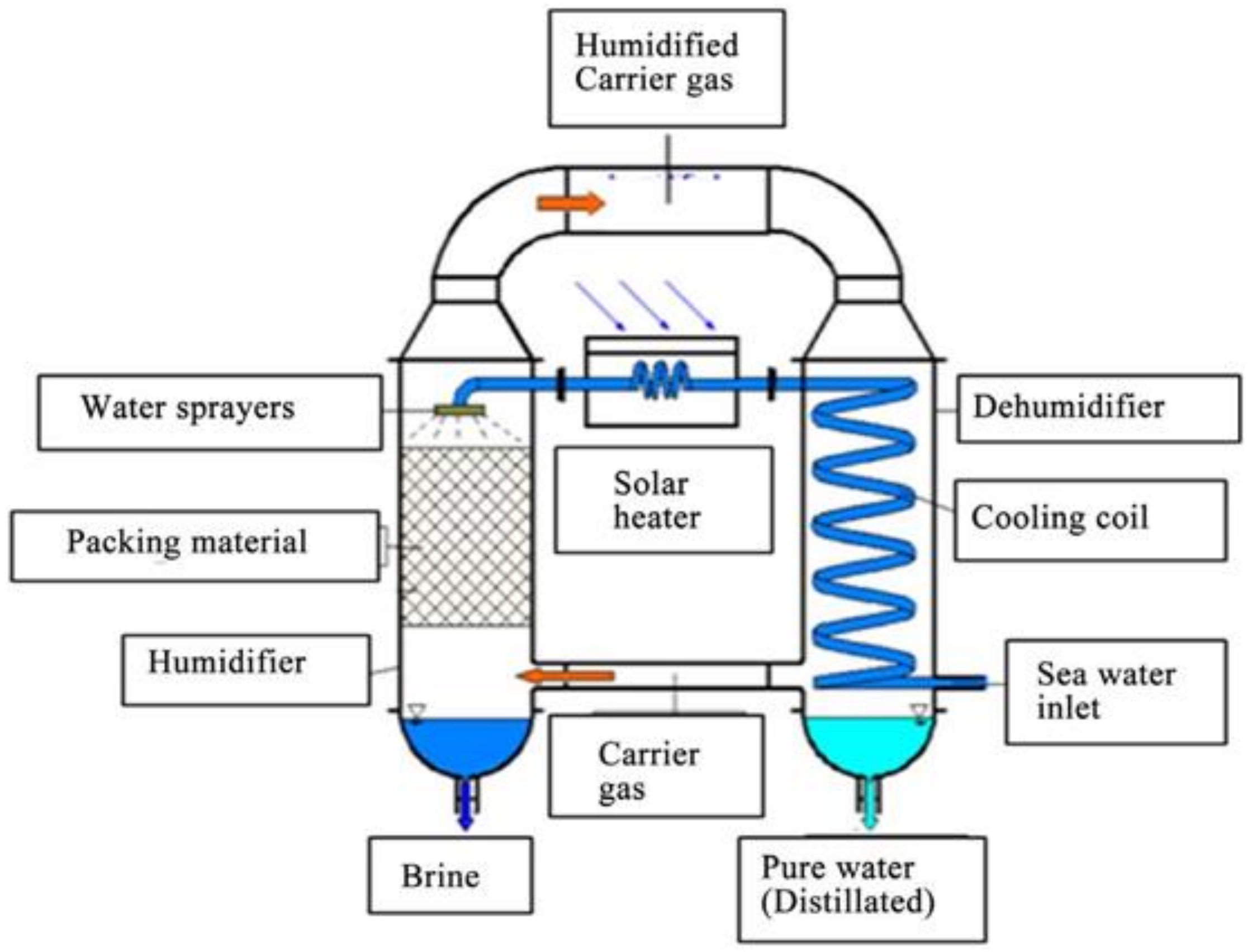
2.1. Instrumentation

The shell and packaging material make up the majority of the humidifier. The shell is composed of polypropylene with an 8 mm thickness and a diameter of 25 cm. The shell’s height is 150 cm. Cut loofah purchased from market is immobilized in the shell. To ensure that saltwater is sprayed uniformly on the packing surface, three polyvinyl chloride nozzles are spaced 10 cm above the packing in a single row. A drain hole is carved into the bottom of the humidifier shell to allow the humidifier’s highly concentrated saltwater to exit. In the cooling water loop and saline water loop, two 0.3 kW centrifugal pumps are employed. The 30 L saline water storage tank is built of polyvinyl chloride (PVC) with a thickness of 2 mm.

2.2. Procedure

The humidification column is supplied with the desired packing mass on each stage, with the saline water shower at its top. The condenser is made to stand upright, vertically parallel to the humidifier. The feed water tank provided with a solar saline water heater is connected to the shower such that a constant flowrate is supplied to the humidifier, and a receiver for saline running down the column is placed. A cooling water loop is provided to the condenser in order to effect vapor condensation, and an air blower is fitted at the side of the humidification column below the lower screen of the bottom-most stage, for introducing air. Finally, the column and condenser, as well as all other parts, are connected by polyethylene tubing. The operation is started, and the volume and salinity of condensate are measured every 30 min and recorded.

2.3. Variables Investigated:

Different variables were studied regarding their effect on the produced water quantity and salinity, and these were as follows:
  • Dry or wet packing.
  • Air flowrate.
  • Mass of packing on each stage.
  • Saline water flowrate.
  • Saline water temperature.
  • Dominance of both flowrates over temperature.

3. Results and Discussions

In the present work, desalination by the HD technique was investigated, in which preliminary experiments were conducted to determine the optimum range of saline solution flowrate, air flowrate, the quantity of packing material used in each stage, number of stages in the humidification column, and the inlet temperature of both saline solution and air, which can produce maximum productivity and least concentration of potable water.
HD has been gaining wide acceptance as a prospective desalination technique, due to its simplicity and cost-effective nature, based on its moderate thermal energy needs, which can be obtained via solar heating of the saline feed; air heating can be dispensed with altogether. Concomitantly, solar pumping may be used for introducing the saline liquid to the top of the humidification column to render the process very cost effective. However, to maximize mass transfer between both liquid and air, a suitable hydrophilic packing with maximum porosity and the maximum surface area should be used within the humidification column, at which water vapor could be transferred from the liquid phase to air, wherein the latter is humidified. In this regard, numerous packing materials have been studied for their suitability, such as metallic rings of various shapes and sizes, fibrous cotton mesh materials, and still many others [13,70,71,72,73,74,75]. However, in this work, a natural hydrophilic cellulosic plant material named “Luffa Aegyptiaca” which is planted on the banks of the River Nile, and which was used for the first time successfully by El-Ashtoukhy [76] as packing material to desalinate saline water by the HD technique, was further studied to determine the optimum conditions under which saline and seawater could be desalinated to give maximum productivity of potable water in a recycle or once-through process.
The results of the present work are presented in Figure 5, Figure 6, Figure 7, Figure 8 and Figure 9. Figure 5 clarifies the effect of using new dry loofah packing and wet used packing, to investigate whether the performance of the latter varies after becoming wet with prolonged use. Two main values were recorded by time: the flux of product water and its concentration to see if the water produced was potable or not.

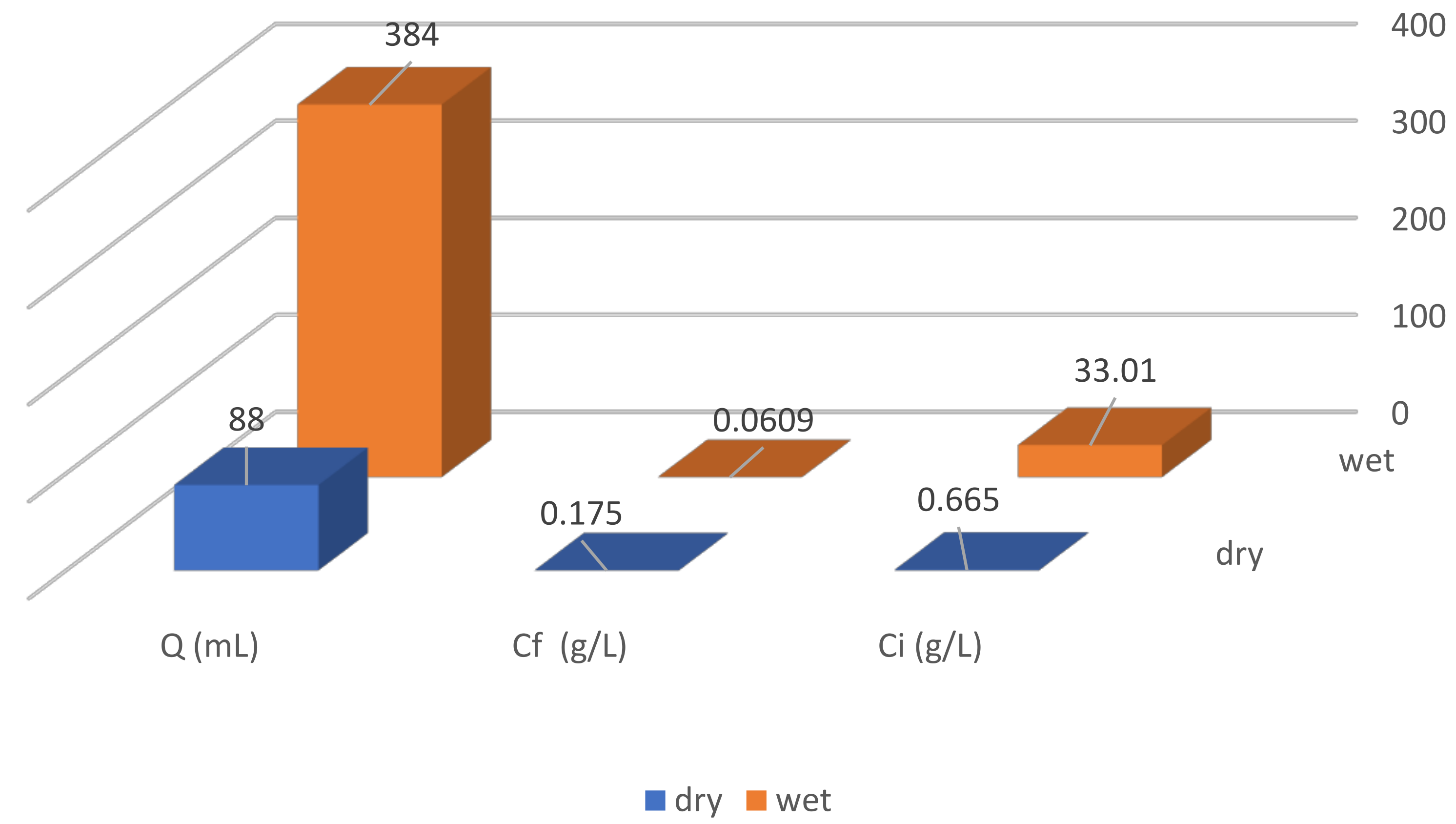
3.1. Effect of Dry or Wetted Packing

Figure 5 depicts the difference in the performance of the wet used packing and the dry unused packing. It is clear that the performance of the loofah packing is enhanced as soon as it becomes fully wetted since contact between water and air along the wet hydrophilic surface of the packing is maximized, and thus, the air becomes well humidified. On the other hand, when the packing is still dry and until it becomes fully wetted, contact between the two phases is minimal, similar to that which takes place in a spray tower. Accordingly, wet packing resulted in more than four times the volume of the dry unused packing. However, as regards the salinity of the product water, it is realized that in both cases, desalination took place, even though tap water was used in the case of the dry packing, where the initial saltwater concentration (Ci = 0.6551 g/L) produced the final water concentration (Cf = 0.1756 g/L). On the other hand, in the other case, Ci simulated seawater concentration (33.01 g/L) and produced almost totally desalinated water (0.0609 g/L). Dry packing does not allow good intimate contact between liquid and air, opposite to the completely wetted surface loofah. This result is of great importance since it proves that the performance of the packing, as regards both quantity and quality, improves during operation.

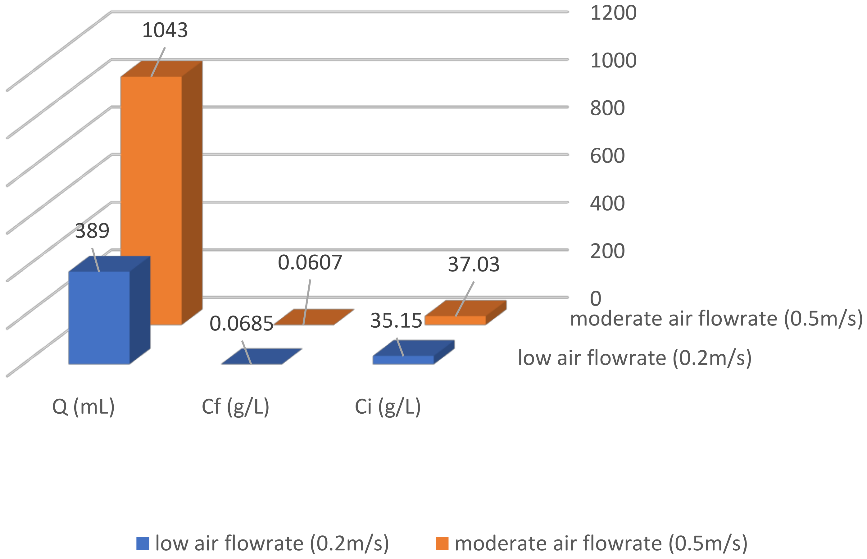
3.2. Effect or Air Flowrate

The effect of the air flowrate on the quantity and quality of the produced water is shown in Figure 6, from which it is clear that at a low air flowrate (0.2 m/s), the produced water after a four-hour operation was 386 mL, whereas at a constant saline water flowrate (300 mL/min) and medium air flowrate (0.5 m/s), the collected water summed up to 1043 mL, despite Ci being 35.15 and 37.03 g/L in respective order. Concomitantly, the salinity of the product water was lower at a medium air flowrate than at a low flowrate. WPR is directly proportional to the amount of air that reaches the condenser. Therefore, moderate flowrates are recommended for both feed water and air since they yield optimum flux and salinity of potable water.

3.3. Effect of Mass of Packing on Each Stage

Figure 7 clarifies the effect of the mass of the loofah packing on each stage: 26 g of loofah is better than 44 g on each stage since the former allows better counter current contact between the two phases, whereas in the latter case, the flowrates are less within the packing than in the mainstream, due to the resistance imposed by the dense packing to the liquid and gas flows. Accordingly, the volume collected in four hours and the concentration of the product water, in the case of using 44 and 26 g of packing on each stage, were 300 and 448 mL, and 0.205 and 0.204 g/L, in respective order. Therefore, it could be stated with confidence that this technique is promising when loofah is used as packing and that, in addition, less loofah mass is recommended for an increased chance of the liquid and air meeting on the loofah surface where the air is humidified.

3.4. Effect of Saline Water Flowrate

In the following figure (Figure 8), the effect of the saline flowrate is presented. Both low and moderate saline flowrates were investigated, together with medium air flowrates and in the presence of 26 g loofah packing on each of the six stages. Ci, in both cases, was 37 g/L. After a four-hour operation, the total volume collected was 768 mL when a moderate saline water flowrate (500 mL/min) was used, compared to 530 mL in the other case (300 mL/min). It is important to note that this result was obtained despite the fact that the saline water temperature was higher (70 °C) in the case where the flowrate was low. This result points out the importance of adjusting both air and saline flowrates such that they are adequate relative to each other so that neither the entrainment of salty water takes place, leading to high salinity of the product water, which is undesirable, nor is the volume less than desired. This result also shows that the flowrates of both liquid and gas and their relative values are the most influential factors affecting the performance of the HD operation. A moderate flowrate of saline water is optimal since more water is available for humidifying the air. However, Cf is less compared with the low flowrate cases, but both are very fresh water. Therefore, moderate saline flowrates are preferred since the productivity is greater.

3.5. Effect of Saline Water Temperature

In this regard, Figure 9 clarifies the effect of the saline water temperature. On comparing these two experiments in which Ci was 37 g/L in both, and in which low air and saline water flowrates were used (0.2 m/s and 300 mL/min in respective order), it is found that the experiment in which the temperature of the saline water (Tsal) was 70 °C gave a higher product volume than that in which Tsal was 50 °C (548 and 258 mL, in respective order). However, the collected volume was in general low, due to both air and saline flowrates being low, which confirms the findings in the previous paragraph that the flowrates are more influential than the feedwater temperature.

4. Conclusions

The present work dealt with the desalination of simulated seawater, by the application of the HD technique, in which an innovated type of biodegradable eco-friendly cellulosic plant material, named loofah, which is planted on the banks of the River Nile in Egypt, was used as the packing material. Though the HD process is a cost-effective method, the main bottleneck was finding a suitable hydrophilic material that could function as a suitable packing material on which both gas and liquid phases could interact, such that proper humidification of air could take place. The best results arrived at in this study were wet packing conditions, 0.5 m/s air flowrate, 26 g packing for each of the 6-stage columns, and 500 mL/min water flowrate at 70 °C. It was shown that the performance of the packing improves with prolonged operation due to its hydrophilic character as it becomes fully wetted, and that the volume of water collected is about four times that when the packing is dry since contact between the two counters current phases is maximized as the surface becomes wetter. In addition, 26 g of properly distributed packing on each stage is better than 44 g, since the latter case simulates a bubble tray column followed by a spray column (between the stages), which is not as efficient as a packed column. Moreover, as regards saline and air flowrates, it was shown that medium flowrates of both phases are recommended since maximum product water of very low salinity in the range of one-tenth that of potable water could be obtained. In addition, it was found that the flowrates of both air and saline streams, and their relative values, are more influential than the temperature of the saline water, which means that low-grade thermal energy sources may be used for heating the saline feed easily and at low cost. This suggests investigating lukewarm saline water as feed to the humidifier, in the future. Loofah, as a good novel packing material in HD in addition to its adsorptive characteristics, is highly recommended for greenhouse HD instead of other costly packing materials.

Author Contributions

Conceptualization, N.G. and M.M.E.; methodology, M.M.E. and A.A.E.-B.; validation, N.G., N.B., M.M.E. and G.E.H.; formal analysis, M.M.E. and N.G.; investigation, M.M.E. and N.G.; resources, A.B. and Y.A.; data curation, Y.A., M.M.E. and A.B.; writing—original draft preparation, M.M.E. and N.G.; writing—review and editing, M.M.E. and A.A.E.-B.; visualization, Y.A. and M.M.E.; supervision, M.M.E. and A.A.E.-B.; project administration, N.G. and G.E.H.; funding acquisition, N.G. and Y.A. All authors have read and agreed to the published version of the manuscript.

Funding

This research is funded by Deputyship for Research & Innovation, Ministry of Education in Saudi Arabia, grant/project number 503.

Institutional Review Board Statement

Not applicable.

Informed Consent Statement

Not applicable.

Data Availability Statement

All the data generated or analysed is contained in this article.

Acknowledgments

The authors extend their appreciation to the Deputyship for Research & Innovation, Ministry of Education in Saudi Arabia for funding this research work through the project number 503.

Conflicts of Interest

The authors declare no conflict of interest. The funders had no role in the design of the study; in the collection, analyses, or interpretation of data; in the writing of the manuscript, or in the decision to publish the results.

References

  1. Wescoat, J.L., Jr.; White, G.F. Water for Life. In Proceedings of the 3rd World Water Forum, Kyoto, Japan, 16–23 March 2003. [Google Scholar]
  2. Kabeel, A.E.; Hamed, M.H.; Omara, Z.M.; Sharshir, S.W. Water Desalination Using a Humidification-Dehumidification Technique—A Detailed Review. Nat. Resour. 2013, 04, 286–305. [Google Scholar] [CrossRef] [Green Version]
  3. United Nations The Millennium Development Goals Report; United Nations: New York, NY, USA, 2015.
  4. Hammond, A.L.; Kramer, W.J.; Katz, R.S.; Tran, J.T.; Tran, J. The Next 4 Billion: Market Size and Business Strategy at the Base of the Pyramid; World Resources Institute: Washington, DC, USA, 2007. [Google Scholar]
  5. Prahalad, C.K.; Hammond, A. Serving the world’s poor, profitably. Harv. Bus. Rev. 2002, 80, 48–124. [Google Scholar] [PubMed]
  6. Abd El Kader, M.; Aref, A.; Moustafa, G.H.; ElHenawy, Y. A Theoretical and Experimental Study for a Humidification-Dehumidification (Hd) Solar Desalination Unit. Eng. Res. J. 2010, 33, 119–130. [Google Scholar] [CrossRef] [Green Version]
  7. Zamen, M.; Soufar, S.M.; Amidpour, M. Improvement of Solar Humidification-Dehumidification Desalination Using Multi-Stage Process. Chem. Eng. Trans. 2011, 25, 1091–1096. [Google Scholar] [CrossRef]
  8. Saidi, S.; Radhia, R.B.; Benhamou, B.; Nafiri, N.; Jabrallah, S. Ben Experimental investigation of a solar powered humidification-dehumidification desalination unit. Desalin. Water Treat. 2017, 62, 1–10. [Google Scholar] [CrossRef]
  9. Mahmoud, M.S. Enhancement of solar desalination by humidification-dehumidification technique. Desalin. Water Treat. 2011, 30, 310–318. [Google Scholar] [CrossRef]
  10. Kabeel, A.E.; Emad El Said, M.S. A Hybrid Solar Desalination System of Air Humidification Dehumidification and Water Flashing Evaporation Part I. A Numerical Investigation. In Proceedings of the Sixteen International Water Technology Conference, IWTC16, Istanbul, Turkey, 7–10 May 2012. [Google Scholar]
  11. Shabaneh, A.A.; Gandhidasan, P.; Antar, M.A.; Baig, H. Simulation of HDH desalination system using tilted, two-pass solar air heater. In Proceedings of the 15th International Water Technology Conference, IWTC, Alexandria, Egypt, 28–30 May 2011. [Google Scholar]
  12. Elhenawy, Y.; Elkader, M.A.; Moustafa, G. A Theoretical Model for a Humidification Dehumidification (HD) Solar Desalination Unit. World Acad. Sci. Eng. Technol. Int. J. Electr. Comput. Energ. Electron. Commun. Eng. 2015, 9, 646–655. [Google Scholar]
  13. Essa, F.A.; Abdullah, A.S.; Omara, Z.M.; Kabeel, A.E.; El-Maghlany, W.M. On the different packing materials of humidification–dehumidification thermal desalination techniques—A review. J. Clean. Prod. 2020, 277, 123468. [Google Scholar] [CrossRef]
  14. Yuan, G.; Zhang, H. Mathematical modeling of a closed circulation solar desalination unit with humidification-dehumidification. Desalination 2007, 205, 156–162. [Google Scholar] [CrossRef]
  15. Yamalı, C.; Solmus, İ. A solar desalination system using humidification–dehumidification process: Experimental study and comparison with the theoretical results. Desalination 2008, 220, 538–551. [Google Scholar] [CrossRef]
  16. Amer, E.H.; Kotb, H.; Mostafa, G.H.; El-Ghalban, A.R. Theoretical and experimental investigation of humidification-dehumidification desalination unit. Desalination 2009, 249, 949–959. [Google Scholar] [CrossRef]
  17. Hermosillo, J.-J.; Arancibia-Bulnes, C.A.; Estrada, C.A. Water desalination by air humidification: Mathematical model and experimental study. Sol. Energy 2012, 86, 1070–1076. [Google Scholar] [CrossRef]
  18. Muthusamy, C.; Srithar, K. Energy and exergy analysis for a humidification-dehumidification desalination system integrated with multiple inserts. Desalination 2015, 367, 49–59. [Google Scholar] [CrossRef]
  19. Al-Hallaj, S.; Farid, M.M.; Rahman Tamimi, A. Solar desalination with a humidification-dehumidification cycle: Performance of the unit. Desalination 1998, 120, 273–280. [Google Scholar] [CrossRef]
  20. Nematollahi, F.; Rahimi, A.; Gheinani, T.T. Experimental and theoretical energy and exergy analysis for a solar desalination system. Desalination 2013, 317, 23–31. [Google Scholar] [CrossRef]
  21. Nafey, A.S.; Fath, H.E.S.; El-Helaby, S.O.; Soliman, A. Solar desalination using humidification–dehumidification processes. Part II. An experimental investigation. Energy Convers. Manag. 2004, 45, 1263–1277. [Google Scholar] [CrossRef]
  22. Bacha, H.B.; Damak, T.; Bouzguenda, M.; Maalej, A.Y. Experimental validation of the distillation module of a desalination station using the SMCEC principle. Renew. Energy 2003, 28, 2335–2354. [Google Scholar] [CrossRef]
  23. Zhani, K.; Ben Bacha, H. Experimental investigation of a new solar desalination prototype using the humidification dehumidification principle. Renew. Energy 2010, 35, 2610–2617. [Google Scholar] [CrossRef]
  24. Garg, H.P.; Adhikari, R.S.; Kumar, R. Experimental design and computer simulation of multi-effect humidification (MEH)-dehumidification solar distillation. Desalination 2003, 153, 81–86. [Google Scholar] [CrossRef]
  25. Eslamimanesh, A.; Hatamipour, M.S. Mathematical modeling of a direct contact humidification–dehumidification desalination process. Desalination 2009, 237, 296–304. [Google Scholar] [CrossRef]
  26. Mittal, M.K.; Varshney, L. Optimal thermohydraulic performance of a wire mesh packed solar air heater. Sol. Energy 2006, 80, 1112–1120. [Google Scholar] [CrossRef]
  27. Ranjitha Raj, P.; Jayakumar, J.S. Performance analysis of humidifier packing for humidification dehumidification desalination system. Therm. Sci. Eng. Prog. 2022, 27, 101118. [Google Scholar] [CrossRef]
  28. Amara, M.B.; Houcine, I.; Guizani, A.; Maalej, M. Theoretical and experimental study of a pad humidifier used in a seawater desalination process. Desalination 2004, 168, 1–12. [Google Scholar] [CrossRef]
  29. Thiel, G.P.; Miller, J.A.; Zubair, S.M.; Lienhard, J.H. Effect of mass extractions and injections on the performance of a fixed-size humidification–dehumidification desalination system. Desalination 2013, 314, 50–58. [Google Scholar] [CrossRef] [Green Version]
  30. Prakash Narayan, G.; St. John, M.G.; Zubair, S.M.; Lienhard, J.H. Thermal design of the humidification dehumidification desalination system: An experimental investigation. Int. J. Heat Mass Transf. 2013, 58, 740–748. [Google Scholar] [CrossRef]
  31. Sharqawy, M.H.; Antar, M.A.; Zubair, S.M.; Elbashir, A.M. Optimum thermal design of humidification dehumidification desalination systems. Desalination 2014, 349, 10–21. [Google Scholar] [CrossRef]
  32. He, W.F.; Wu, F.; Wen, T.; Kong, Y.P.; Han, D. Cost analysis of a humidification dehumidification desalination system with a packed bed dehumidifier. Energy Convers. Manag. 2018, 171, 452–460. [Google Scholar] [CrossRef]
  33. Faegh, M.; Shafii, M.B. Performance evaluation of a novel compact humidification-dehumidification desalination system coupled with a heat pump for design and off-design conditions. Energy Convers. Manag. 2019, 194, 160–172. [Google Scholar] [CrossRef]
  34. Wu, G.; Zheng, H.; Ma, X.; Kutlu, C.; Su, Y. Experimental investigation of a multi-stage humidification-dehumidification desalination system heated directly by a cylindrical Fresnel lens solar concentrator. Energy Convers. Manag. 2017, 143, 241–251. [Google Scholar] [CrossRef]
  35. Lawal, D.U.; Antar, M.A.; Khalifa, A.; Zubair, S.M.; Al-Sulaiman, F. Experımental investigation of heat pump driven humidification-dehumidification desalination system for water desalination and space conditioning. Desalination 2020, 475, 114199. [Google Scholar] [CrossRef]
  36. Nawayseh, N.K.; Farid, M.M.; Al-Hallaj, S.; Al-Timimi, A.R. Solar desalination based on humidification process—I. Evaluating the heat and mass transfer coefficients. Energy Convers. Manag. 1999, 40, 1423–1439. [Google Scholar] [CrossRef]
  37. Abdullah, A.S.; Essa, F.A.; Omara, Z.M.; Bek, M.A. Performance evaluation of a humidification–dehumidification unit integrated with wick solar stills under different operating conditions. Desalination 2018, 441, 52–61. [Google Scholar] [CrossRef]
  38. Dai, Y.J.; Zhang, H.F. Experimental investigation of a solar desalination unit with humidification and dehumidification. Desalination 2000, 130, 169–175. [Google Scholar] [CrossRef]
  39. Xu, H.; Zhao, Y.; Dai, Y.J. Experimental study on a solar assisted heat pump desalination unit with internal heat recovery based on humidification-dehumidification process. Desalination 2019, 452, 247–257. [Google Scholar] [CrossRef]
  40. Yanniotis, S.; Xerodemas, K. Air humidification for seawater desalination. Desalination 2003, 158, 313–319. [Google Scholar] [CrossRef]
  41. Al-Enezi, G.; Ettouney, H.; Fawzy, N. Low temperature humidification dehumidification desalination process. Energy Convers. Manag. 2006, 47, 470–484. [Google Scholar] [CrossRef]
  42. Klausner, J.F.; Li, Y.; Mei, R. Evaporative heat and mass transfer for the diffusion driven desalination process. Heat Mass Transf. 2006, 42, 528–536. [Google Scholar] [CrossRef]
  43. Kabeel, A.E.; El-Said, E.M.S. A hybrid solar desalination system of air humidification, dehumidification and water flashing evaporation: Part II. Experimental investigation. Desalination 2014, 341, 50–60. [Google Scholar] [CrossRef]
  44. Kabeel, A.E.; Hamed, M.H.; Omara, Z.M.; Sharshir, S.W. Experimental study of a humidification-dehumidification solar technique by natural and forced air circulation. Energy 2014, 68, 218–228. [Google Scholar] [CrossRef]
  45. Zubair, S.M.; Antar, M.A.; Elmutasim, S.M.; Lawal, D.U. Performance evaluation of humidification-dehumidification (HDH) desalination systems with and without heat recovery options: An experimental and theoretical investigation. Desalination 2018, 436, 161–175. [Google Scholar] [CrossRef]
  46. Moumouh, J.; Tahiri, M.; Salouhi, M.; Balli, L. Theoretical and experimental study of a solar desalination unit based on humidification–dehumidification of air. Int. J. Hydrog. Energy 2016, 41, 20818–20822. [Google Scholar] [CrossRef]
  47. Farshchi Tabrizi, F.; Khosravi, M.; Shirzaei Sani, I. Experimental study of a cascade solar still coupled with a humidification–dehumidification system. Energy Convers. Manag. 2016, 115, 80–88. [Google Scholar] [CrossRef]
  48. Sachdev, T.; Gaba, V.K.; Tiwari, A.K. Performance analysis of desalination system working on humidification-dehumidification coupled with solar assisted air heater and wind tower: Closed and open water cycle. Sol. Energy 2020, 205, 254–262. [Google Scholar] [CrossRef]
  49. Zhang, L.; Yue, Y.; Shi, M.; Tian, M.; Ji, J.; Liao, X.; Hu, X.; Chen, F. Dietary Luffa cylindrica (L.) Roem promotes branched-chain amino acid catabolism in the circulation system via gut microbiota in diet-induced obese mice. Food Chem. 2020, 320, 126648. [Google Scholar] [CrossRef] [PubMed]
  50. Chen, Y.; Yuan, F.; Su, Q.; Yu, C.; Zhang, K.; Luo, P.; Hu, D.; Guo, Y. A novel sound absorbing material comprising discarded luffa scraps and polyester fibers. J. Clean. Prod. 2020, 245, 118917. [Google Scholar] [CrossRef]
  51. Kocak, D.; Mistik, S.I.; Akalin, M.; Merdan, N. The use of Luffa cylindrica fibres as reinforcements in composites. In Biofiber Reinforcements in Composite Materials; Elsevier: Amsterdam, The Netherlands, 2015; ISBN 9781782421276. [Google Scholar]
  52. Khadir, A.; Negarestani, M.; Mollahosseini, A. Sequestration of a non-steroidal anti-inflammatory drug from aquatic media by lignocellulosic material (Luffa cylindrica) reinforced with polypyrrole: Study of parameters, kinetics, and equilibrium. J. Environ. Chem. Eng. 2020, 8, 103734. [Google Scholar] [CrossRef]
  53. Kong, Q.; He, X.; Shu, L.; Miao, M. sheng Ofloxacin adsorption by activated carbon derived from luffa sponge: Kinetic, isotherm, and thermodynamic analyses. Process Saf. Environ. Prot. 2017, 112, 254–264. [Google Scholar] [CrossRef]
  54. Saeed, A.; Iqbal, M. Loofa (Luffa cylindrica) sponge: Review of development of the biomatrix as a tool for biotechnological applications. Biotechnol. Prog. 2013, 29, 573–600. [Google Scholar] [CrossRef]
  55. Oboh, I.O.; Aluyor, E.O.; Audu, T.O.K. Application of Luffa Cylindrica in Natural form as Biosorbent to Removal of Divalent Metals from Aqueous Solutions—Kinetic and Equilibrium Study. In Waste Water; Einschlag, F.S.G., Ed.; IntechOpen: Rijeka, Croatia, 2011. [Google Scholar]
  56. Xiao, F.; Cheng, J.; Cao, W.; Yang, C.; Chen, J.; Luo, Z. Removal of heavy metals from aqueous solution using chitosan-combined magnetic biochars. J. Colloid Interface Sci. 2019, 540, 579–584. [Google Scholar] [CrossRef]
  57. Zeng, L.; Liu, Q.; Lu, M.; Liang, E.; Wang, G.; Xu, W. Modified natural loofah sponge as an effective heavy metal ion adsorbent: Amidoxime functionalized poly(acrylonitrile-g-loofah). Chem. Eng. Res. Des. 2019, 150, 26–32. [Google Scholar] [CrossRef]
  58. Kong, Q.; Wang, Y.; Shu, L.; Miao, M. Isotherm, kinetic, and thermodynamic equations for cefalexin removal from liquids using activated carbon synthesized from loofah sponge. Desalin. Water Treat. 2016, 57, 7933–7942. [Google Scholar] [CrossRef]
  59. Yu, J.; Wang, L.; Chi, R.; Zhang, Y.; Xu, Z.; Guo, J. Removal of cationic dyes: Basic magenta and methylene blue from aqueous solution by adsorption on modified loofah. Res. Chem. Intermed. 2013, 39, 3775–3790. [Google Scholar] [CrossRef]
  60. Caicedo, O.; Devia-Ramirez, J.; Malagón, A. Adsorption of Common Laboratory Dyes Using Natural Fibers from Luffa cylindrica. J. Chem. Educ. 2018, 95, 2233–2237. [Google Scholar] [CrossRef]
  61. Mashkoor, F.; Nasar, A. Preparation, characterization and adsorption studies of the chemically modified Luffa aegyptica peel as a potential adsorbent for the removal of malachite green from aqueous solution. J. Mol. Liq. 2019, 274, 315–327. [Google Scholar] [CrossRef]
  62. Paton, D.P.; Paton, C.; Davies, P. The seawater greenhouse for arid lands. In Proceedings of the Mediterranean Conference on Renewable Energy Sources for Water Production, Santorini, Greece, 10–12 June 1996; pp. 163–166. [Google Scholar]
  63. Davies, P.; Turner, K.; Paton, C. Potential of the Seawater Greenhouse in Middle Eastern Climates. In Proceedings of the Engineering Conference, Tehran, Iran, 26–28 April 2004; pp. 523–540. [Google Scholar]
  64. Davies, P.A.; Paton, C. The seawater greenhouse in the United Arab Emirates: Thermal modelling and evaluation of design options. Desalination 2005, 173, 103–111. [Google Scholar] [CrossRef]
  65. Al-Ismaili, A.M.; Jayasuriya, H. Seawater greenhouse in Oman: A sustainable technique for freshwater conservation and production. Renew. Sustain. Energy Rev. 2016, 54, 653–664. [Google Scholar] [CrossRef]
  66. Shekarchi, N.; Shahnia, F. A comprehensive review of solar-driven desalination technologies for off-grid greenhouses. Int. J. Energy Res. 2019, 43, 1357–1386. [Google Scholar] [CrossRef]
  67. Goosen, M.F.; Sablani, S.; Paton, C.; Perret, J.; Al-Nuaimi, A.; Haffar, H.; Al-Hinai, H.; Shayya, W. Solar energy desalination for arid coastal regions: Development of a humidification–dehumidification seawater greenhouse. Sol. Energy 2003, 75, 413–419. [Google Scholar] [CrossRef]
  68. Sablani, S.S.; Goosen, M.F.A.; Paton, C.; Shayya, W.H.; Al-Hinai, H. Simulation of fresh water production using a humidification-dehumidification seawater greenhouse. Desalination 2003, 159, 283–288. [Google Scholar] [CrossRef]
  69. Perret, J.S.S.; Al-Ismaili, A.M.M.; Sablani, S.S.S. Development of a Humidification-Dehumidification System in a Quonset Greenhouse for Sustainable Crop Production in Arid Regions; Elsevier: Amsterdam, The Netherlands, 2005; Volume 91. [Google Scholar]
  70. Chiranjeevi, C.; Srinivas, T.; Raj, A.; Shankar, R. Experimental investigation on a coconut coir packed humidifier for a solar desalination plant. Prog. Ind. Ecol. 2019, 13, 280. [Google Scholar] [CrossRef]
  71. Shalaby, S.M.; Kabeel, A.E.; El-Bialy, E. Investigation and improvement of the humidification–Dehumidification solar water desalination system implemented wick as packing material. J. Sol. Energy Eng. Trans. 2020, 142, 1–26. [Google Scholar] [CrossRef]
  72. Thanaiah, K.; Gumtapure, V.; Mitiku Tadesse, G. Experimental analysis on humidification-dehumidification desalination system using different packing materials with baffle plates. Therm. Sci. Eng. Prog. 2021, 22, 100831. [Google Scholar] [CrossRef]
  73. Patel, P.; Vadalia, B.V.; Patel, J. Solar Humidification- Dehumidification Technology For Pure Water Production. Int. J. Sci. Res. Dev. 2014, 1, 2231–2235. [Google Scholar]
  74. Hady, F.A.; El-Halwagi, M.M.; Alghamdi, M.; Mazher, A.K.; Alzahrani, A. Experimental Study of Humidification AndDehumidification Desalination Process. Int. J. Eng. Technol. 2018, 10, 511–528. [Google Scholar] [CrossRef] [Green Version]
  75. Lawal, D.; Antar, M.; Khalifa, A.; Zubair, S.; Al-Sulaiman, F. Humidification-dehumidification desalination system operated by a heat pump. Energy Convers. Manag. 2018, 161, 128–140. [Google Scholar] [CrossRef]
  76. El-Ashtoukhy, E.-Z. An Innovated Unit for the Desalination of Seawater by Humidification–Dehumidification of Air. Ph.D. Thesis, Alexandria University, Alexandria, Egypt, 2006. [Google Scholar]
Figure 1. The simplest embodiment of the HD process [2].
Water 14 00869 g001
Figure 2. Classification of HD systems based on cycle configurations.
Water 14 00869 g002
Figure 3. (A) The concept of solar HD -based greenhouse and (B) solar HD-based greenhouse in Oman [66].
Water 14 00869 g003
Figure 4. Schematic of HD experimental setup.
Water 14 00869 g004
Figure 5. Effect of dry and wet packing after 2 h operation.
Water 14 00869 g005
Figure 6. Effect of air flowrate after 4 h operation.
Water 14 00869 g006
Figure 7. Effect of mass of packing on each stage at 75 °C.
Water 14 00869 g007
Figure 8. Effect of saline water flowrate.
Water 14 00869 g008
Figure 9. Effect of saline water temperature.
Water 14 00869 g009
Table 1. Summary of research works on the structure and random packing in the humidifier [27].
Packing MaterialCharacteristics of the PackingEffect on ProductivityGained Output Ratio (GOR)Ref.
Corrugated cellulosic pad humidifierThe pad has a cross-sectional area of 0.3 m × 0.6 m and a thickness of 0.75 m.N/AN/A[28]
CF-1900SB/MAN/AN/A5.65[29]
Polypropylene, CF1200 MAa = 226 m2/m3700 L/day4[30]
Cross-fluted film fill media.N/A10 L/h1.93[31]
Polypropylene, Sulzer Mellapak 250 YN/A84.60 kg/h1.44[32]
CF1200MA Cross Fluted Film Fill MediaN/A0.91 L/h2.476[33]
Ceramic black corrugated packinga = 350 m2/m3 and porosity = 0.783.4 kg/h2.1[34]
Corrugated aluminium sheet packing650 mm × 650 mm × 650 mm size15 kg/hN/A[34]
Structured cellulose padsa = 400 m2/m3 and total wetted surface area of the packing = 8.1 m2287.8 L/day4.07[35]
Wooden slatesa = 87 m2/m38 l/m2 dayN/A[19]
Wooden packinga = 58 m2/m3N/AN/A[36]
Aspen pads and cellulose paperN/A70 L/day7.3[37]
Honeycomb paperN/A6.2 kg/m2 dayN/A[38]
Honeycomb paper type of packingN/A14.3 kg/kWh1.93[39]
Gunny and saw dust type of humidifier packingN/A0.476 kg/hN/A[18]
Canvas type of humidifier packingN/A2 kg/hN/A[21]
Plastic spray humidifier and corrugated cellulosic pad humidifierSpray humidifier D = 0.30 m, L = 4 m, and thickness 0.10 mN/AN/A[40]
Plastic packingCylindrical shape with D = 8 mm, L = 12 mmN/AN/A[41]
HD-QPAC Plastic packinga = 267 m2/m3
D = 1.8 cm
N/AN/A[42]
Plastic Pad type packingD = 5 cm, L = 5 cm41.8 kg/dayN/A[43]
Cellulose paperN/A23.6 kg/hN/A[44]
Cellulose padsTotal height of 65 cmN/AN/A[45]
Metal packinga = 200 m2/m3N/AN/A[46]
Pall ringD = 16 mm5.4 kg/m2 dayN/A[47]
Clay conduit columnN/A0.2 L/h4.17[48]
Publisher’s Note: MDPI stays neutral with regard to jurisdictional claims in published maps and institutional affiliations.

