
Temporal Scour Variations at Permeable and Angled Spur Dikes under Steady and Unsteady Flows


1
Department of Hydraulic Structures, Faculty of Water and Environmental Engineering, Shahid Chamran University of Ahvaz, Golestan Boulevard, Ahvaz 61357-43311, Iran
2
School of Engineering, University of Basilicata, Viale dell’Ateneo Lucano 10, I-85100 Potenza, Italy
*
Author to whom correspondence should be addressed.
Water 2022, 14(20), 3310; https://doi.org/10.3390/w14203310
Submission received: 27 September 2022
/
Revised: 14 October 2022
/
Accepted: 18 October 2022
/
Published: 20 October 2022
(This article belongs to the Special Issue Sediment Transport at Bridges and River Training Structures)
Abstract
:Spur dikes are river protection structures typically used for flow diversion from erodible banks. However, scouring might be a severe problem that compromises their stability and, consequently, their hydraulic function. This paper aims to study the maximum scour depth at permeable and angled spur dikes under hydrographs of different duration. Experiments were carried out in a rectangular channel 10 m long, 0.76 m wide, and 0.6 m deep. The mobile bed was made of nearly uniform sand with a median grain size of 0.8 mm. A total of 36 new experiments were performed with a detailed data collection over the time (i.e., 216 datasets), which could provide a useful contribution to the topic. The impact of the spur dike orientation angle, θ, and the degree of permeability, φ, on the temporal scour evolution were explored. Results were found physically consistent and revealed that the spur dike permeability implies a significant attenuation of the scouring processes in comparison to the impermeable spur dikes and generally its effect is more beneficial than that from a favorable orientation angle. The differences in percentage between the maximum scour depth for impermeable spur dikes and the maximum scour depths for various degrees of spur dike permeability were found ranging from 44% (at φ = 33% and θ = 60°) up to 88% (at φ = 66% and θ = 120°). Other results include the effect of the hydrograph base-time on the scour depth and the comparison between scouring processes under steady and unsteady flow conditions. By quadrupling the hydrograph base-time, keeping constant the peak and base flood discharges, the maximum scour depths increased by about 29%, 42%, and 25% in case of impermeable spur dike, spur dike with 33% degree of permeability, and spur dike with 66% degree of permeability. Furthermore, starting from dimensional analysis a new empirical model (with coefficient of determination R2 equal to 0.94) is introduced to predict the time-dependent scour depth due to the passage of a flood wave. The model suggests that the main independent dimensionless variables which control local scour processes are: the densimetric Froude number, the time t normalized to the hydrograph base-time, the degree of permeability, and the orientation angle. These dimensionless variables would generalize the laboratory results to the real-world scenarios, although caution should always be taken because of possible scale effects.
1. Introduction
Rivers play an important role in human existence and development, and are sometimes referred to as the “cradle of civilization”. Many hydraulic works such as dams, diversion weirs, spillways, banks, dykes, and bridges are developed to manage and regulate rivers to efficiently satisfy human development demands [1,2]. Scour and erosion processes at the bed and banks of natural rivers as well as waterways (i.e., irrigation or navigation channels), are major challenges that need to be tackled efficiently for proper water resources management. Scour processes in water bodies are the primary cause of geomorphic changes leading to land loss, excessive sediment yield, and subsequent degradation of water quality [3].
Spur dikes are hydraulic works that cross the river flow and run along the bank. They are frequently applied to protect the river banks and increase water depth [4]. As a result, spur dikes generate local hydraulic changes in the flow around themselves, as well as between them and along the bank [5]. Probably, Ahmad [6] conducted the first experimental study on spur dikes. He discussed the flow non-uniformity in such a field by observing fluctuations in water level around a single spur dike in a straight channel. Chen and Ikeda [7] studied the flow patterns around a single spur dike in a straight line and found that transient vortices were splitted from the spur dike tip and transported downstream alternatively. They discovered that the mean migration velocity of the vortices was nearly steady and its value was a little over 1.5 percent of the average flow velocity. Flow structures around a spur dike may greatly vary, exhibiting three-dimensional features in its vicinity. These complex flow structures scale with the size of the spur dike and flow velocity, containing sufficient energy for the removal of bed material leading to the generation of local scour [8,9,10].
The study of scouring processes and their negative impacts near the spur dike is critical for river operation and management [11]. Local scour is well defined in fluvial hydraulics as the removal of sediment particles from alluvial streams. It is an important geomorphic process that affects virtually all hydraulic infrastructures, ranging from bridge piers [12] to embankments and riverbanks [13] and it is recognized as the primary cause of the failure of spur dikes [14]. On the basis of experiments on spur dikes with various orientation angles (30°, 60°, and 90° relative to the downstream), Ezzeldin et al. [15] reported that the angle of 30° was optimal in terms of scour depth and bank protection.
In river engineering projects, spur dikes are utilized in both permeable and impermeable forms. Although extensive studies on impermeable spur dikes have been performed, there are comparatively few articles on permeable spur dikes. Among these, Cao et al. [16] reported the design and implementation of permeable spur dikes by gathering and classifying the studies conducted in this area. Li et al. [17] emphasize that the flow penetrates the structure to some extent in permeable spur dikes, resulting in a considerable drop in velocity, vortex intensity, and shear force at the spur dike nose. As a result, the maximum scouring depth at the spur dike nose would significantly decrease [18]. Permeable spur dikes have even more stability and require less maintenance than impermeable spur dikes [19]. Zhang and Nakagawa [20] evaluated the scouring of single permeable and impermeable spur dikes, determining that the maximum scour depth around the permeable spur dike is less than half than that around an impermeable spur dike.
Depending on whether the approach flow is sediment laden or clear-water, scour around spur dikes might be classified as: clear-water scour and live-bed scour. Clear-water scour develops in the absence of sediment transport by approaching flow into the scour hole while in case of live-bed scour the scour hole is continuously fed with bed materials by the approaching flow [21]. Teraguchi et al. [22] provided detailed information on the flow patterns and bed deformation around bandal-like structures under live-bed scour and non-submerged conditions. Under the same hydraulic conditions, the conventional structures like impermeable and permeable spur dikes were tested to check similarities and differences between them and the bandal-like structures.
The findings of steady flow tests, in which the quantity of flow rate is equal to the peak flow discharge of the flood hydrograph, are typically used to establish the maximum scour depth in the design of the hydraulic works (with a specified return period). The flow characteristics, and therefore the factors causing the scour, change with time in flood waves, and the scour depth after the passage of a flood wave is less than that at the equilibrium stage for steady flow conditions with a discharge equal to the peak flow rate [23]. The bridge piers are the focus of most investigations in the area of scouring under unsteady flows [24]. Most studies even consider the equilibrium scour depth under steady flows for estimating scouring processes around bridge piers. According with some studies in the eighties, the time necessary in a lab to get equilibrium conditions is around 50 h. But a similar (or even greater) time for a real flood in nature may be beyond the realistic boundaries because except for major rivers, the flood peak in most rivers is substantially shorter [1,3]. As a result, in typical rivers the real scour depth may be less than that at the equilibrium stage because the flood durability could be insufficient to achieve such equilibrium conditions [2,4,5]. Therefore, using the peak flood flow rate under steady flow with test of long duration results in equilibrium scour depths that doesn’t match those under unsteady flow conditions. Therefore, considering steady flows conditions might greatly overestimate the scour depth [6,7]. Furthermore, Melville and Chiew [25] found that at the time equal to 10% of the equilibrium time the scour depth would account for 50–80% of the maximum ultimate scour depth. Thus, the scour depth of a flood that lasts, for example, 10% of the equilibrium time is from 20 to 50 percent less than the equilibrium scour depth. In other words, due to the fact that considerable scour processes mainly occur during floods, it would be important to analyze the relationship between flood hydrographs and the temporal progress of the scour depth. The current design of spur dike foundations based on the equilibrium scour depth can lead to significant overestimations because the equilibrium scour depth can be much larger than the real maximum scour depth since peak flood periods are often too short to reach equilibrium conditions. As a result, it would be important to consider the flood hydrograph to compute the scour depth corresponding to the peak flow rate instead of considering steady flow conditions [3,8]. Considering the common conditions encountered in nature, it is still required to study scouring around spur dikes under unsteady flows.
Therefore, the present study aims to investigate such conditions at laboratory scales. Moreover, the effects of the orientation angle and the degree of permeability are also considered in order to cover the real-world scenarios as close as possible. The topic is complex, but this study would like to provide new insights on local scour at spur dikes, although through a simplified scaled situation of the real-world scenario, as often it occurs in most literature studies. The novelties of this study consist in a new collection of experimental data (also provided in detail as supplementary file) on local scour at spur dikes under steady and unsteady flows and a new predictive equation on the time-dependent scour depth due to the passage of a flood wave.
2. Materials and Methods
2.1. Experiments
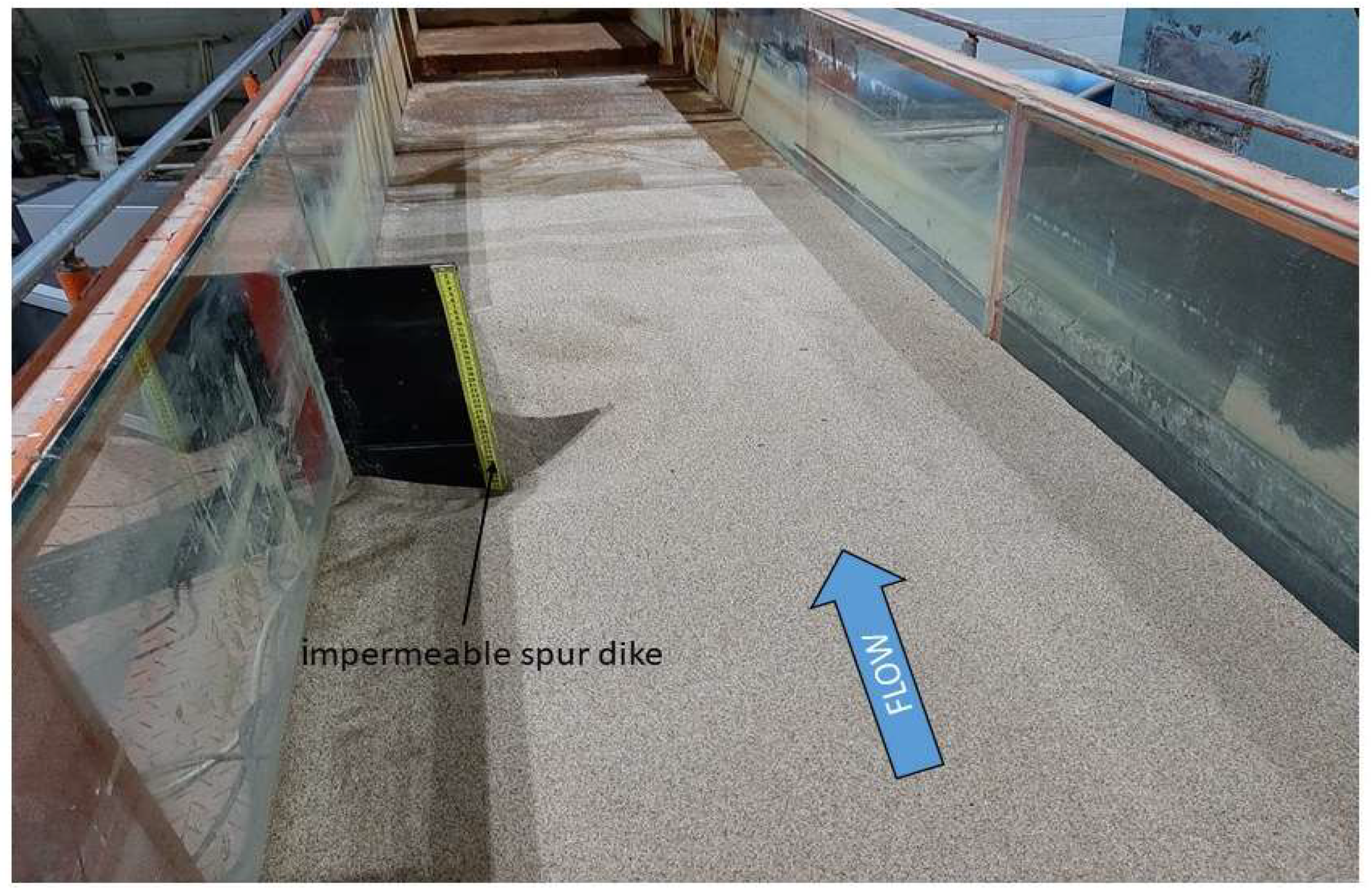
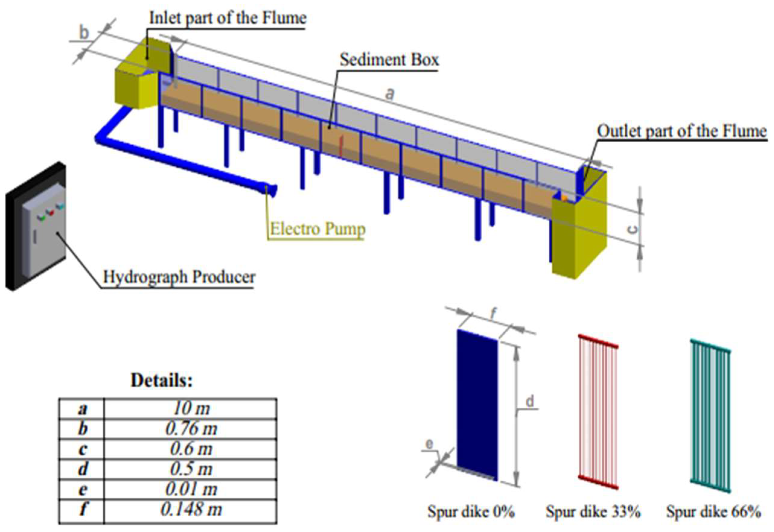
Experiments were carried out at the Hydraulic Laboratory of the Shahid Chamran University of Ahvaz (Iran) in a flume 10 m long, 0.76 m wide, and 0.60 m deep. The flume had glass walls, inlet and outlet tanks as well as an initial section to moderate the flow. An end valve was used to regulate the flow depth. The flume was first filled at a modest rate to minimize undesirable scouring processes due to sheet flows. Tests were carried out in a sediment recess section, 4.0 m from the inlet. The mobile bed was made of sand with a relative density of 2.65 and median grain size d50 equal to 0.8 mm. The gradation of the sediment mixture that can be described by the standard deviation σg = (d84/d16)0.5 was equal to 1.22 which would imply an almost uniform sediment [26]. d84 and d16 are the particle sizes for which 84% and 16% of the sediment mixture are finer, respectively. In the present study, a single unsubmerged spur dike was considered with three levels of permeability, namely 0% (i.e., impermeable spur dike), 33%, and 66%. Moreover, three spur dike orientation angles θ equal to 60° (repelling alignment), 90° (deflecting alignment), and 120° (attractive alignment) were considered. θ is the angle between the spur dike and the upstream wall. A Plexiglas plate 0.5 m high and 10 mm thick was employed to simulate an impermeable spur dike. Brass rods with a height of 0.5 m and a diameter of 4 mm, which were fixed to two Plexiglas plates at the top and bottom, were used to simulate a permeable spur dike. The effective length of the spur dike for the repelling, deflecting, and attractive alignments was always equal to 20% of the flume width. Figure 1 shows a view of the flume with an impermeable spur dike looking from upstream.
A computer-based software system, a controller circuit with software interface and inverter, a pump with electric motor, and an electromagnetic flow meter allowed the generation of unsteady flows. These components enabled the development of hydrographs of different durations and shapes with an accuracy of 0.1 L/s. Clearly also steady flows could be generated. In particular, a system with two parts, software and hardware, was designed to generate unsteady flows. This system provided orders to the motor to modify the engine speed and, as a result, the flow rate. The user-hardware system interface was a computer-based program that accepted the user′s hydrograph in the form of an Excel file and delivered the appropriate instructions to the system to modify the flow rate after conducting the needed processing. An electromagnetic flow rate meter (MagAb 3000, Iran Madar Company, Shiraz, Iran) with an accuracy of ±0.25 L/s was mounted in the pump′s inlet pipe, which recorded the passing flow rate for every tenth of a second, allowing the system to accurately verify the required flow at any moment. After leveling the bed, the end valve of the flume was set to a depth greater than the desired one, then the pump was switched on and water flowed through the flume at a very low flow rate, of a few liters per second, to progressively saturate the bed. After the water level in the flume increased preventing any movement of the mobile bed, the valve was gradually regulated to get the beginning depth of the flow for the hydrograph’s base flow rate; then the pump started to work according to the specific test. Each experiment was video recorded and photographed using a special underwater camera (Digital Borescope 008 mm - 3 m Model), whose images were transmitted to a computer at the start of the experiment and during the passage of the hydrograph. Scour depths were then collected using photos obtained at any moment using the free GetData Graph Digitizer software version 2.26. A bed profiler took the topographic coordinates of the bed, with an accuracy of 0.1 mm, after each run. This device used a moving rail to propel its bathometer laser across the flume′s width, which was controlled by the user using the device′s interface software. The device was longitudinal positioned manually by the user. The collected data (x, y, and z values) was saved in an Excel file on a backup computer. Figure 2 depicts a graphical image of the flume and some schemes for the spur dikes utilized in this experimental work.
The experiments performed in this study were divided into two categories: steady and unsteady flows. Both steady and unsteady flow experiments were set in order to ensure clear-water scour regimes also when the hydrograph peak flow was reached. The critical velocity VC at the incipient sediment motion was estimated using the following well-known equation VC/u*C = 5.75log[h/(2d50)] + 6 in which the shear velocity u*C was computed according to the Shields’ diagram and h is the approach flow depth. Local scour processes did not occur around the spur dike when the flow rates were less than 15 L/s and the flow depth was 13.7 cm. As a result, the hydrographs began with a 15 L/s base flow. Consistently with the experimental facilities, the hydrograph base times were 15, 30, or 60 min.
The influences of the spur dike orientation angle and degree of permeability on the temporal variations of scour depth for hydrographs with base-time of 15, 30, and 60 min were explored, which included 27 runs and 162 datasets. Each dataset includes the time t, the discharge Q, the approach flow depth h, and the maximum scour depth ds at the given time t. In addition, 9 runs under steady flow conditions were performed to allow a comparison with the findings from unsteady flow conditions and hydrograph base-time equal to 60 min. In this case 54 datasets were collected. Then, a total of 36 runs were carried out in this study. The rationality behind this number of runs is as follows. In case of unsteady flows our intention was to investigate: (i) the effect of the spur dike orientation angle considering the typical (and equidistant) angle values of 60° (repelling alignment), 90° (deflecting alignment), and 120° (attractive alignment); (ii) the effect of the degree of permeability considering the three equidistant values of 0%, 33%, and 66%; (iii) the effect of the hydrograph base-time considering the three values of 15, 30, and 60 min. Therefore, the combination of all the possible values of these variables leads to a total of 33 = 27 runs. Likewise in case of steady flows our intention was to compare the maximum scour depths observed for unsteady flows and hydrograph base-time equal to 60 min to the maximum scour depths observed for steady flow runs of duration equal to 60 min and approach flow conditions corresponding to those at the hydrograph peak flow. Therefore, all the possible combinations lead to a total of 32·1 = 9 runs. All the experimental data are provided in a supplementary file associated with this article. The scour depth around the nose of the spur dike was monitored over the time, this being the region in which the maximum scour depth occurred, at least for runs of short duration, as in this study. Moreover, the discharge and the flow depth over the time were measured for the purposes of characterization of the approach flow conditions.
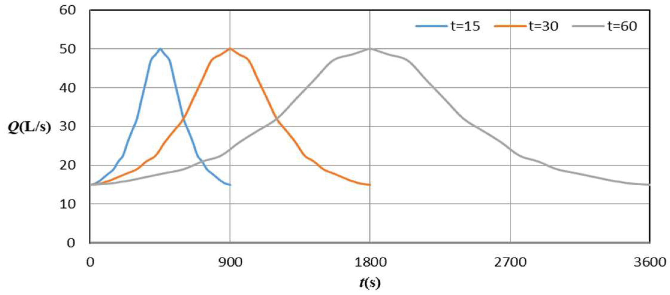
Figure 3 shows the three hydrographs used in this study. They were symmetric and the peak discharge was always the same (i.e., 50 L/s). However, the base times were different and equal to 15, 30, and 60 min.
Moreover, Table 1 shows the hydraulic and geometric conditions for the experiments in more details. Qb, Qp, h, F, Fd, V/VC, tb, θ, and φ are the: hydrograph base discharge, hydrograph peak discharge, approach flow depth, approach Froude number, approach densimetric Froude number, approach flow intensity, hydrograph base-time, spur dike orientation angle, and spur dike degree of permeability, respectively. V is the approach flow velocity and VC is the approach flow velocity at the bed particles incipient motion. The densimetric Froude number Fd will be defined later.
Based on the above, scale effects were negligible mainly because: (i) sidewall effects were not significant being the ratio of the approach flow depth to the channel width overall greater than 4 ÷ 5 [27]; (ii) the effective length L of the spur dike was always 20% of the flume width B. Therefore, the effects of lateral flow contraction on local scour around the spur dike were minimized as indicated in Özyaman et al. [28] according to the contraction effect plays an active rule when the contraction ratio L/B is greater that 0.29 for uniform sediments and 0.36 for non-uniform sediments with medium sand; (iii) according to Oliveto and Hager [26], viscosity effects at the interface flow-sediment were negligible because in this study d50 was equal to 0.80 mm.
2.2. Dimensional Analysis
Denoting ds as the maximum scour depth around the spur dike at the time t, one can assume the following functional relationship
in which V, h, ρ, ν, ρs, d50, σg, Vc, g, L, θ, φ, tb, and t represent: average approach flow velocity, approach flow depth, water density, kinematic viscosity of water (= 10−6 m2/s), sediment density, sediment median grain size, sediment gradation, threshold velocity for particle entrainment, gravitational acceleration, spur dike length, spur dike orientation angle, spur dike degree of permeability, base-time of hydrograph, and time, respectively. In sediment-water interaction it is appropriate to represent the independent parameters g, ρ, and ρs as a combined parameter Δg where Δg = s − 1 and s relative density of sediment that is ρs/ρ [26,29]. Moreover, the influence of the kinematic viscosity n can be considered negligible under a fully turbulent flow over a rough bed [29] as in this study. Using the dimensional analysis with repeating variables V and L, and rearranging the nondimensional parameters logically [29], yields
where Fd is the densimetric Froude number defined as V/[(s = 1)gd50]0.5. The role of Fd in local scour processes was well emphasized by Oliveto and Hager [26], who also show that the effect of L on ds is preponderant compared to the approach flow depth h. It should be noted that d50/L and σg were kept constant in this study.
To generalize the laboratory results to the real-world scales the values of the dimensionless parameters in the model and the original sample must be equal. This is provided that scale effects are negligible, as it would seem to be in this study.
On the basis of the functional relationship (2), a new empirical model will be introduced later to predict the time-dependent scour depth due to the passage of a flood wave. The accuracy of the proposed model will be evaluated using three performance evaluation criteria including: (i) the root-mean-square error (RMSE); (ii) the mean absolute error (MAE); and (iii) the coefficient of determination (R2), defined in Equations (3)–(5), respectively [30]:
in which X and X′ are the experimental and calculated values of ds/L, respectively, and N is the total number of the experimental data collected in this study. Actually, in case of unsteady flow conditions N was equal to 317 and not only 162 because additional observations were acquired during the runs outside of the default monitoring times.
3. Results
The experiments were planned to explore the impact of important spur dike characteristics such as the orientation angle on the flow and the degree of permeability. All this with reference to the more realistic conditions of unsteady flows. Furthermore, the effects of the duration of the hydrograph on the scouring process were examined.
3.1. Impact of the Spur Dike Orientation Angle on the Temporal Scour Development
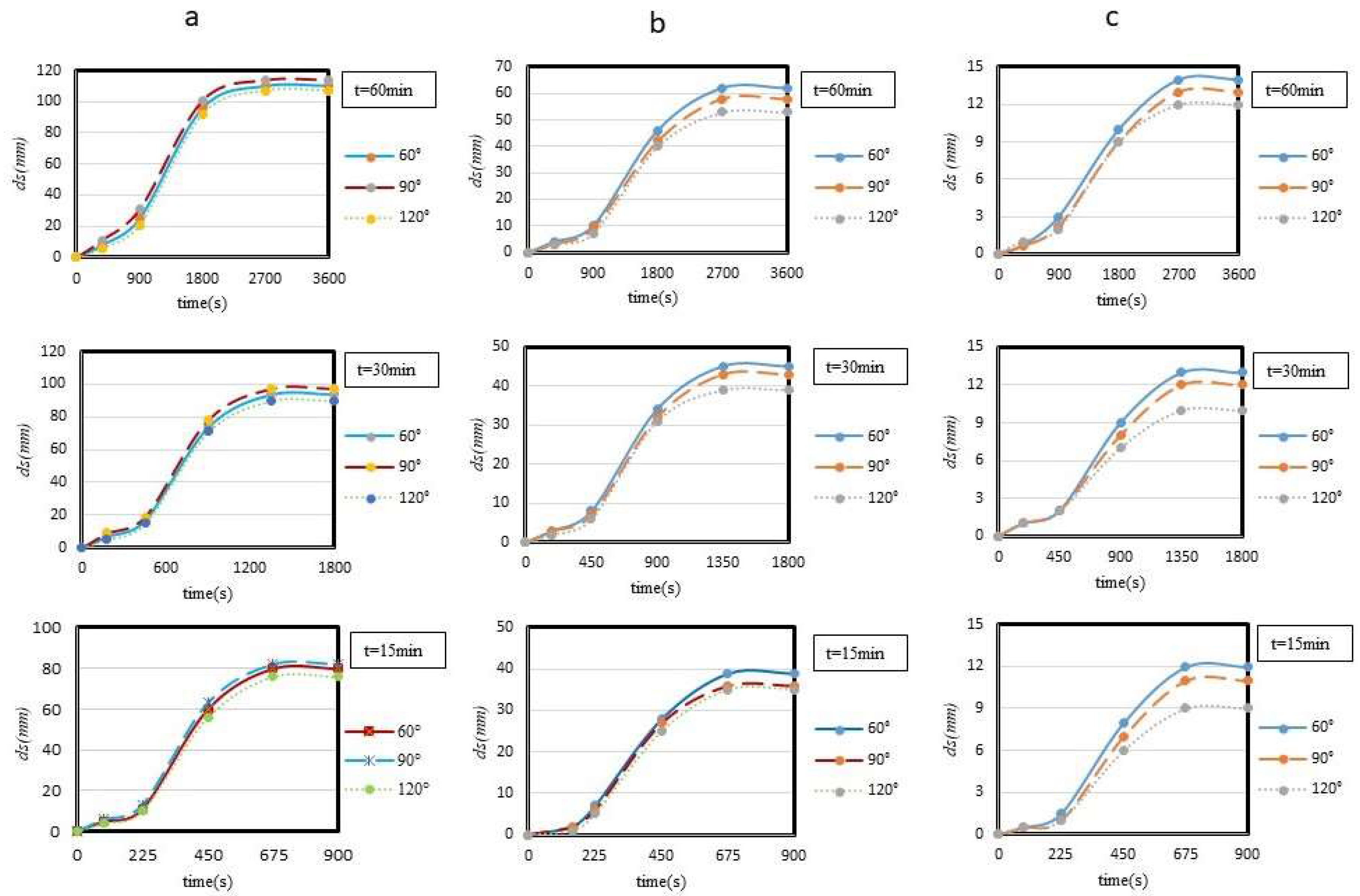
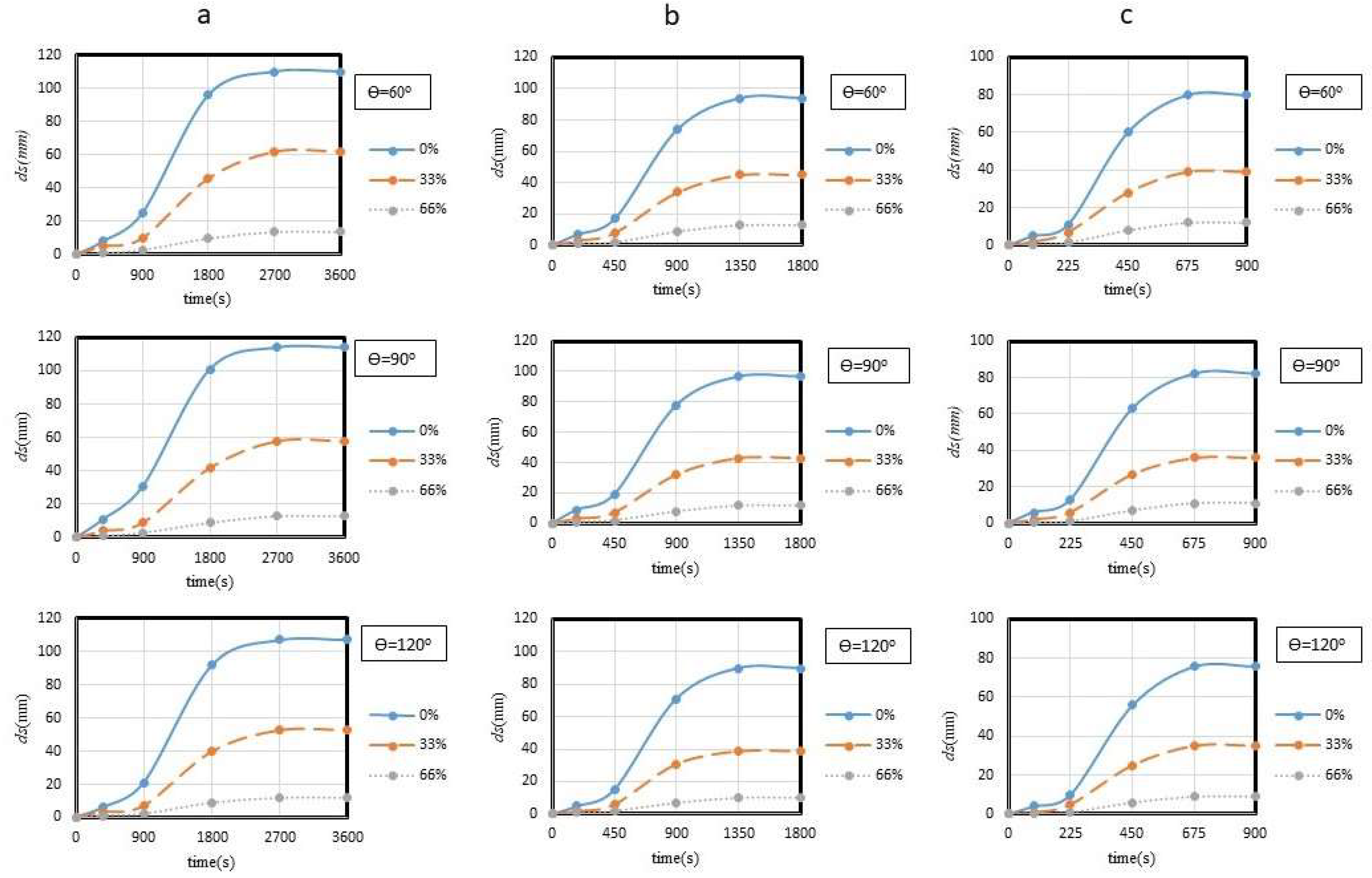
The individual panel in Figure 4 shows the temporal trends of the maximum scour depth under the hydrographs with base-time of 60, 30, and 15 min. Moreover, for each hydrograph duration the three orientation angles θ of 60°, 90°, and 120° are considered. As already mentioned above, for θ = 60° the spur dike points upstream, for θ = 90° it is normal to the approach flow direction, and for θ = 120° it points downstream. Panel (a) refers to the runs with impermeable spur dikes, panel (b) to the runs for spur dikes with 33% permeability, and panel (c) to the runs for spur dikes with 66% permeability. ds is the observed scour depth in millimeters.
Table 2 shows the differences in percentage between the maximum scour depth and the scour depth at the hydrograph peak with the influence of the spur dike orientation angle in evidence.
3.2. Impact of the Spur Dike Permeability on the Temporal Scour Development
The influence of the spur dike permeability on the temporal variation of the scour depth under unsteady flows is shown in Figure 5. The panel “a” of Figure 5 refers to the runs lasting 60 min, the panel “b” to the runs lasting 30 min, and the panel “c” to the runs lasting 15 min. In regard to the characteristics of the spur dike, each plot refers to the different degrees of permeability (i.e., 0%, 33%, and 66%) at a given orientation angle θ.
Table 3 quantifies the above findings by comparing the maximum scour depths observed at permeable spur dikes with those at impermeable ones for 60, 30, and 15-min hydrographs and orientation angles of spur dikes equal to 60°, 90°, and 120°.
3.3. Impact of the Duration of the Hydrograph on the Temporal Scour Development
The effects of the base-time of the hydrograph on the temporal scour development at spur dikes with different orientation angles and degrees of permeability are shown in Figure 6. In particular, the temporal trends of the scour depth under the hydrographs with base-times of 15, 30, and 60 min are considered. As shown, when the time-base increases from 15 to 60 min the maximum scour depth increases by about 26%, 37%, and 18% in case of impermeable spur dike, spur dike with 33% degree of permeability, and spur dike with 66% degree of permeability, respectively.
Table 4 shows the differences in percentage between the maximum scour depths for the 60-min hydrograph and the maximum scour depths for the 15 and 30-min hydrographs at various spur dike orientation angles and degrees of permeability.
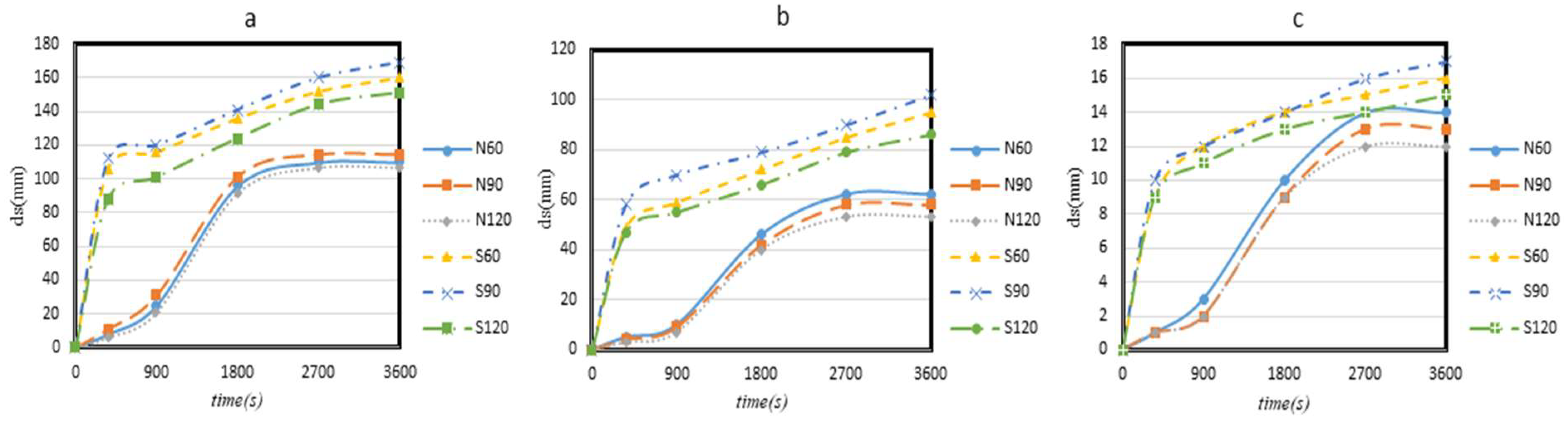
3.4. Comparison of the Scouring Conditions under Steady and Unsteady Flows
Some tests were carried out, for various orientation angles and permeability degrees, under steady flows for durations corresponding to those considered under unsteady flows and flow discharges equal to the hydrograph peak flows. Figure 7 shows the temporal trend of the maximum scour depth under steady flow for a test duration of 1 h and for: impermeable spur dike (Figure 7a), spur dike with 33% permeability (Figure 7b) and spur dike with 66% permeability (Figure 7c). The letters S, N, and the angle value in degrees denote steady flow, unsteady flow, and spur dike orientation angle, respectively. For example, runs denoted by S60 and N60 refer to the temporal changes in scour depth around a spur dike with a 60° orientation angle under steady and unsteady flows, respectively.
Table 5 shows the percentage difference between the maximum scour depth under steady flow (and reached at the end of the run after 60 min) and the maximum scour depth under unsteady flows for various spur dike orientation angles and degree of permeability.
3.5. A New Empirical Model for Temporal Scour Development under Unsteady Flows
In this section, a novel empirical formula to predict the temporal variation of the scour depth at a single spur dike under unsteady flows is proposed by also including the effects of the orientation angle and permeability. The following empirical relationships were achieved from regression analysis by using the statistical software package SPSS version 26.0. For this purpose, 75% and 25% of the 317 data for ds under unsteady flows were used for calibration and validation, respectively (e.g., [30]). For t/tb > 0.63 the experimental observations revealed that ds/L remained constant while for t/tb ≤ 0.63 the experimental data were analyzed by nonlinear regression, which implies a nonlinear combination of the model parameters. Therefore,
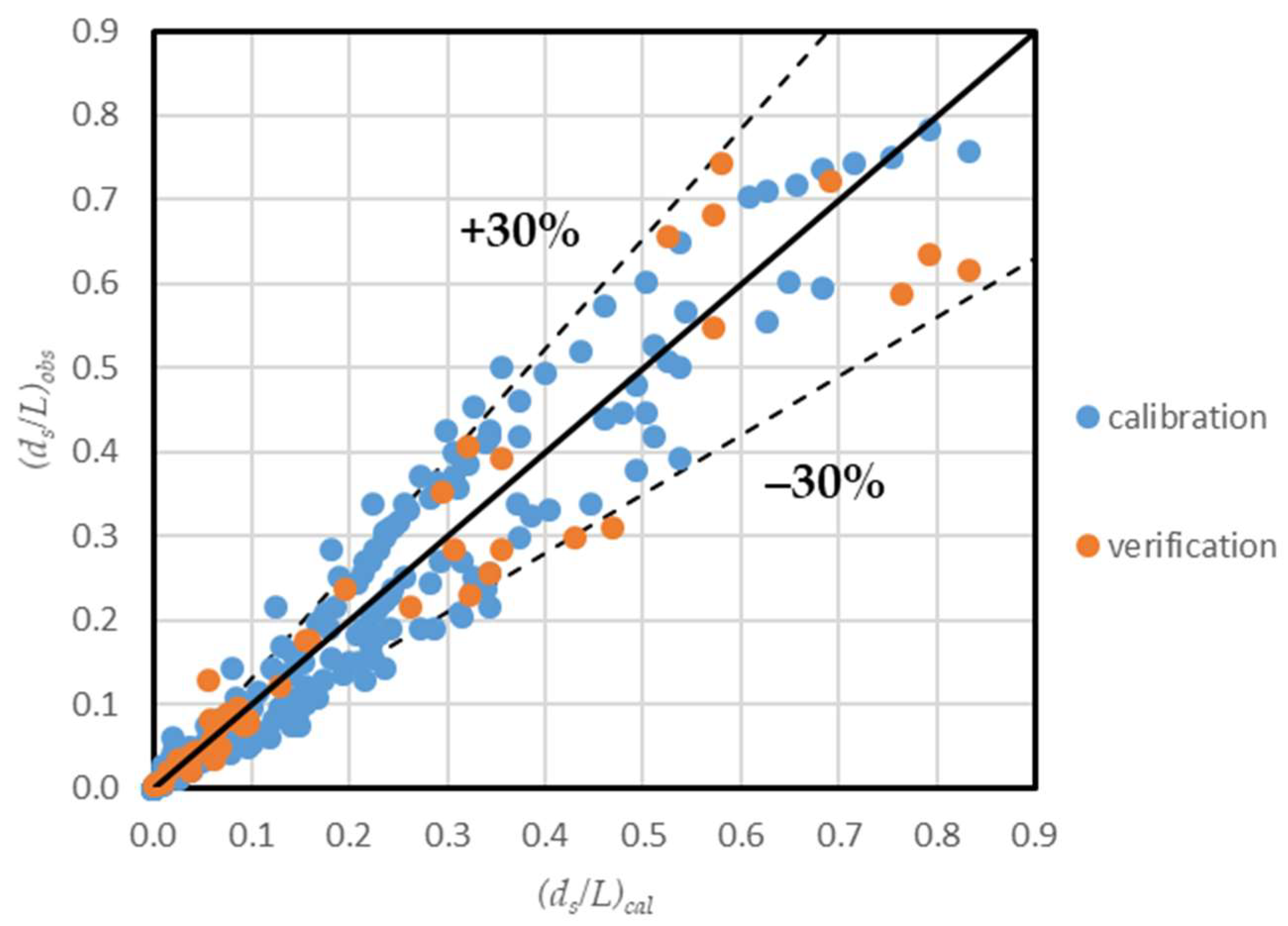
The effect of the other dimensionless variable in the relationship (2) was found negligible. Figure 8 shows the comparison between observed and computed values of the relative scour depths under unsteady flows. It should be noted that 86% of the experimental data is within the ±30% deviation bounds [26] and this especially occurs for the values of ds which were observed at the hydrograph peak. Moreover, the coefficient of determination, R2, was found equal to 0.94, indicating a satisfactory fitting effect.
The values of RMSE, MAE, and R2 for the proposed model were 0.052, 0.034, and 0.94 when considering all the data, confirming a satisfactory scour depth prediction. More specifically the values of RMSE, MAE, and R2 were 0.047, 0.032, and 0.935, respectively, in case of calibration and 0.069, 0.042, and 0.91, respectively, in case of validation.
4. Discussion
The comparison of the scour depth variations over the time for different orientation angles θ of the spur dike (Figure 4) appears to indicate that θ has limited impact on the maximum scour depth especially for impermeable spur dikes. This was probably due to the fact that the effective length of the spur dike for repelling, deflecting, and attractive alignments was always 20% of the flume width. In addition, due to the reduction in flow along the falling limb of the hydrograph, the maximum scouring depth achieves a constant value after roughly 63% of the duration of the hydrograph. In other terms, the scouring process would continue for a certain period of time after the hydrograph peak and during the falling limb of the hydrograph; therefore, the maximum scour depth would occur in the decreasing phase of the approaching discharges. Interestingly, similar findings were achieved for the scouring processes around the bridge piers under unsteady flows [31]. Although differences were not very marked, the plots in the panel (a) (i.e., impermeable spur dikes) in Figure 4 revealed that scour depths were maximum for θ around 60° and 90° and minimum for θ = 120°. Panels (b) and (c) in Figure 4 (i.e., spur dikes with permeability 33% and 66%, respectively) clearly show that the maximum scour depths were attained in case of spur dikes repelling the approaching flows (i.e., θ = 60°). In summary, comparing the plots in Figure 4 one can observe that the orientation angle of the spur dike has no relevant influence on the scouring process-or more precisely on the scour depth-especially in case of impermeable spur dikes. The effect of θ is more prominent in case of permeable spur dikes. From Table 2 it is interesting to observe that these changes increase as the spur dike permeability increases for given values of the base-time and the spur dike orientation angle. This could be due to the fact that with increasing the degree of permeability of the spur dike the amount of flow through the bars increases and the action of the resulting jets tend to continue also during the hydrograph falling limb.
From Figure 5 it is evident that the spur dike permeability has a strong influence on the maximum scour depth around the spur dike so that scouring processes significantly reduce as the degree of permeability increases. The movement of water through the open spur dike rods would break the downflow, thus reducing the strength of the horseshoe vortices. After half of the hydrograph duration, 70% to 90% of the maximum scour depth typically occurs. Similarly, Chang et al. [32] found that raising the flow velocity till its maximum value at the peak hydrograph generates significant changes in scour depth, but after that scour depth changes would be very low in the falling limb. The peaking discharge or the rising limb of the hydrograph had the greatest influence on the scour in all circumstances, whereas the falling limb had little impact. Oliveto and Hager [33] achieved the same results, both from observations and simulations. Table 3 also makes it clear that the degree of permeability would mitigate the scouring processes consistently. A contribute to this is also provided by increasing the orientation angle, but in a much blander way.
Figure 6 and Table 4 show that the base-time of the hydrograph has a major impact on the scouring processes because of a more prolonged action in time especially of the shear stresses related to the discharges closest to the peak discharge. Furthermore, the experimental observations on the temporal variation of the scour depth caused by short-term hydrographs demonstrated that the final scour depth was slightly lower than that measured just before. This probably because of the short duration of the flows that determined high shear stresses and that allowed vortices to dig sediment particles on the top of the scour cavity. Nevertheless, because of the limited durability of high shear stresses, the vortices weakened and were unable to carry the sediment particles downstream and out of the scouring cavity, causing the particles to re-deposit. The shear stresses that exceed the sediment-particle entrainment would last longer as the durability of the hydrograph grows, having more time to put the particles in motion and allow them to pass through the upward slope of the scour cavity [34]. Because the peak flow occurs only temporarily during unsteady flows and is insufficient to stabilize the scour depth, the flow intensity around the spur dike remains over the threshold even when the discharge declines after the passage of the flood peak, thus the scouring process continues. Yet, increasing the scour depth at the maximum point while simultaneously lowering the discharge in the falling limb reduces the local shear stresses applied to the bed to the point where the flow intensity at the maximum scour depth is less than that at the particle motion threshold. As a result, when a period has passed since the peak time, it will be seen the scouring cease at the point in which the maximum scour depth occurs, but scouring continues in some locations, and the dimensions of the scouring cavity grow, although the maximum scouring depth remains constant [1].
Figure 7 shows that the results from steady flow runs differ significantly in comparison to those for unsteady flows, as expected. The trends of the temporal variations in scour depth are also distinct. Because the maximum discharge is applied from the starting of the runs under steady flow conditions, scour depths increase at a faster rate than unsteady flow runs. Conversely, the discharge starts from lesser values under unsteady flow conditions, therefore the temporal variations in scour depth develop at a slower rate, stopping and stabilizing in the falling limb. On the other hand, scour processes did not reach an equilibrium condition under steady flows since the duration of one hour was clearly insufficient in that regard.
The maximum scour depths for steady flows were significantly higher in comparison to the corresponding scour depths under unsteady flows. The maximum percentage differences were observed for the spur dikes with an orientation angle of 90° and this for the various degrees of permeability considered in the present study. In addition, spur dikes with 66% permeability determined the smallest percentage differences in comparison to the spur dikes with the other degrees of permeability (i.e., 0% and 33%). It is confirmed that also under steady flows scour processes tend to be less strong as the degree of permeability increases. The major cause for the mitigation of scour is due to an increase in passing flow through the spur dike and the reduction of the flow power. From Table 5 appears that another distinction between steady and unsteady flow runs is that the maximum scour depth under steady flows does not stabilize after the complete hydrograph period while it becomes stable after around 63% of the hydrograph base time under unsteady flows. The sediment particles on the bed surface were exposed to significant shear stresses during the raising limb of the hydrographs and set in motion, followed by the underneath particles still subjected to high shear stresses. Despite the lowering of the approach velocities in the falling limb of the hydrographs, the scouring process still was active due to the inadequate scouring time in the rising limb to attain the bed morphology stability. In other terms, the strength of the local flow around the spur dike in the falling limb was still higher to determine further scouring progress. As a result, the scouring process in falling limb remained active until the depth of the bed climbed to the point where the shear stresses were no longer able to move the sediment particles, which occurred at the maximum scour depth. The reduced flow rates and flow intensities in the falling limb, however, caused this stop to emerge faster and the maximum scour depth to be fixed.
Equations (6) and (7) are then proposed to compute the scour depth under the hydrograph passage, based on the analysis of experimental data and nonlinear regression, which implies a nonlinear combination of the model parameters. Evidently the effect of densimetric Froude number, Fd, should be more investigated on larger ranges of approach flow conditions and sediment characteristics. However, Equations (6) and (7) clearly demonstrate the strong impact of the degree of permeability of spur dikes on local scour processes.
5. Conclusions
This study provides new experimental data on local scour around spur dikes. Special hydraulic and geometric conditions were explored at laboratory scale including: unsteady flows, spur dike permeability, and spur dike orientation angle. Studying the effect of unsteady flows and comparing the results to steady flow conditions then added a further complexity. The main results can be summarized as follows:
- The orientation angle θ of the spur dike had not relevant effect on the scour depth especially in case of impermeable spur dikes. The impact of θ was increasingly evident although always restricted with increasing the degree of permeability;
- The spur dike permeability had a consistent effect on the scour depth around the spur dike with the scouring process reducing significantly as the degree of permeability increases. The differences in percentage between the maximum scour depth for impermeable spur dikes and the maximum scour depths for various degrees of spur dike permeability were found ranging from 44% (at φ = 33% and θ = 60°) up to 88% (at φ = 66% and θ = 120°);
- By quadrupling the hydrograph base-times, keeping constant the peak and base flood discharges, the maximum scour depths increased by about 29%, 42%, and 25% in case of impermeable spur dike, spur dike with 33% degree of permeability, and spur dike with 66% degree of permeability, respectively;
- The results from steady flow experiments were significantly different in comparison to those for unsteady flows, as expected. The maximum percentage differences in terms of maximum scour depths were observed for spur dikes with an orientation angle of 90° and this for various degrees of permeability;
- Finally, a new empirical formula was developed based on the experimental data collected in this study. The ranges of applications are those related to this experimental work.
However additional experimental data including those from literature would be needed for a more consistent identification of the role of the different variables, especially the densimetric Froude number and the relative approach flow depth. More in general, the effect of multiple spur dikes on scour (and not only on the maximum scour depth) and deposition phenomena would be of special interest.
Supplementary Materials
The following supporting information can be downloaded at: https://www.mdpi.com/article/10.3390/w14203310/s1, Table S1: Experimental Data Collection.
Author Contributions
Conceptualization, R.F., S.M.K. and M.G.; methodology, S.M.K. and R.F.; experimental measurements and data curation, R.F.; formal analysis, R.F. and S.M.K.; investigation, R.F. and S.M.K.; resources, R.F.; writing—original draft preparation, R.F. and S.M.K.; writing, review and editing, S.M.K. and G.O.; visualization, G.O.; supervision, S.M.K. and M.G. All authors have read and agreed to the published version of the manuscript.
Funding
This research was supported by the Khuzestan Water and Power Authority (KWPA) the contract No. 99-22-22-008 and Research Council of the Shahid Chamran University of Ahvaz.
Institutional Review Board Statement
Not applicable.
Informed Consent Statement
Not applicable.
Data Availability Statement
Experimental data that support the findings of this study are available from the first author upon request.
Acknowledgments
The authors are grateful to the Khuzestan Water and Power Authority (KWPA) for its financial support through the contract No. 99-22-22-008 with the Shahid Chamran University of Ahvaz. In addition, the financial and moral support from the Research Council of the Shahid Chamran University of Ahvaz is highly appreciated and thanked.
Conflicts of Interest
The authors declare no conflict of interest.
References
- Pinter, N.; Jemberie, A.A.; Remo, J.W.F.; Heine, R.A.; Ickes, B.S. Cumulative impacts of river engineering, Mississippi and Lower Missouri rivers. River Res. Appl. 2010, 26, 546–571. [Google Scholar] [CrossRef]
- Cao, X.-M.; Gu, Z.-H. Three classification criteria and their comparison impact scale between double non-submerged spur dikes. J. Zhejiang Univ. 2015, 49, 200–207. [Google Scholar]
- Pandey, M.; Valyrakis, M.; Qi, M.; Sharma, A.; Lodhi, A.S. Experimental assessment and prediction of temporal scour depth around a spur dike. Int. J. Sediment Res. 2021, 36, 17–28. [Google Scholar] [CrossRef]
- Shampa; Hasegawa, Y.; Nakagawa, H.; Takebayashi, H.; Kawaike, K. Three-dimensional flow characteristics in slit-type permeable spur dike fields: Efficacy in riverbank protection. Water 2020, 12, 964. [Google Scholar] [CrossRef] [Green Version]
- Gu, Z.; Cao, X.; Gu, Q.; Lu, W.-Z. Exploring proper spacing threshold of non-submerged spur dikes with ipsilateral layout. Water 2020, 12, 172. [Google Scholar] [CrossRef] [Green Version]
- Ahmad, M. Experiments on design and behavior of spur dikes. In Proceedings of the International Hydraulics Convention; University of Minnesota: Minneapolis, MN, USA, 1953; pp. 145–159. [Google Scholar]
- Chen, F.-Y.; Ikeda, S. Horizontal separation flows in shallow open channels with spur dikes. J. Hydrosci. Hydraul. Eng. 1997, 15, 15–30. [Google Scholar]
- Diplas, P.; Dancey, C.L.; Celik, A.O.; Valyrakis, M.; Greer, K.; Akar, T. The role of impulse on the initiation of particle movement under turbulent flow conditions. Science 2008, 322, 717–720. [Google Scholar] [CrossRef] [Green Version]
- Valyrakis, M.; Diplas, P.; Dancey, C.L.; Greer, K.; Celik, A.O. Role of instantaneous force magnitude and duration on particle entrainment. J. Geophys. Res. Earth 2010, 115, F02006. [Google Scholar] [CrossRef]
- Valyrakis, M.; Diplas, P.; Dancey, C.L. Entrainment of coarse particles in turbulent flows: An energy approach. J. Geophys. Res. Earth 2013, 118, 42–53. [Google Scholar] [CrossRef] [Green Version]
- Zhang, L.; Wang, H.; Zhang, X.; Wang, B.; Chen, J. The 3-D morphology evolution of spur dike scour under clear-water scour conditions. Water 2018, 10, 1583. [Google Scholar] [CrossRef] [Green Version]
- Valyrakis, M.; Michalis, P.; Zhang, H. A new system for bridge scour monitoring and prediction. In Proceedings of the 36th IAHR World Congress, The Hague, The Netherlands, 28 June–3 July 2015. [Google Scholar]
- Liu, D.; Valyrakis, M.; Williams, R. Flow hydrodynamics across open channel flows with riparian zones: Implications for riverbank stability. Water 2017, 9, 720. [Google Scholar] [CrossRef] [Green Version]
- Kothyari, U.C.; Ranga Raju, K.G. Scour around spur dikes and bridge abutments. J. Hydraul. Res. 2001, 39, 367–374. [Google Scholar] [CrossRef]
- Ezzeldin, M.M.; Saafan, T.A.; Rageh, O.S.; Nejm, L.M. Local scour around spur dikes. In Proceedings of the Eleventh International Water Technology Conference, IWTC11, Sharm El-Sheikh, Egypt, 15–18 March 2007; pp. 779–795. [Google Scholar]
- Cao, Y.; Liu, P.; Enhui, J. The design and application of permeable groynes. Appl. Mech. Mat. 2013, 353–356, 2502–2505. [Google Scholar] [CrossRef]
- Li, Z.; Michioku, K.; Maeno, S.; Ushita, T.; Fujii, A. Hydraulic characteristics of a group of permeable groins constructed in an open channel flow. J. Appl. Mech. 2005, 8, 773–782. [Google Scholar] [CrossRef]
- Fukuoka, S.; Watanabe, A.; Kawaguchi, H.; Yasutake, Y. A study of permeable groins in series installed in a straight channel. Proc. Hydraul. Eng. 2000, 44, 1047–1052. [Google Scholar] [CrossRef]
- Kang, J.; Yeo, H.; Kim, S.; Ji, U. Permeability effects of single groin on flow characteristics. J. Hydraul. Res. 2011, 49, 728–735. [Google Scholar] [CrossRef]
- Zhang, H.; Nakagawa, H. Scour Around Spur Dyke: Recent Advances and Future Researches; Annuals of Disaster Prevention Research Institute, No. 51B; Kyoto University: Kyoto, Japan, 2008; pp. 633–652. [Google Scholar]
- Pandey, M.; Ahmad, Z.; Sharma, P.K. Estimation of maximum scour depth near a spur dike. Can. J. Civil. Eng. 2016, 43, 270–278. [Google Scholar] [CrossRef] [Green Version]
- Teraguchi, H.; Nakagawa, H.; Kawaike, K.; Baba, Y.; Zhang, H. Morphological Change Induced by River Training Structures: Bandal-like and Groins; Annuals of Disaster Prevention Research Institute, No. 51B; Kyoto University: Kyoto, Japan, 2010. [Google Scholar]
- Link, O.; Castillo, C.; Pizarro, A.; Rojas, A.; Ettmer, B.; Escauriaza, C.; Manfreda, S. A model of bridge pier scour during flood waves. J. Hydraul. Res. 2017, 55, 310–323. [Google Scholar] [CrossRef]
- Raikar, R.V.; Hong, J.-H.; Deshmukh, A.R.; Guo, W.-D. Parametric study on abutment scour under unsteady flow. Water 2022, 14, 1820. [Google Scholar] [CrossRef]
- Melville, B.W.; Chiew, Y.-M. Time scale for local scour at bridge piers. J. Hydraul. Eng. ASCE 1999, 125, 59–65. [Google Scholar] [CrossRef]
- Oliveto, G.; Hager, W.H. Temporal evolution of clear-water pier and abutment scour. J. Hydraul. Eng. ASCE 2002, 128, 811–820. [Google Scholar] [CrossRef]
- Graf, W.H.; Altinakar, M.S. Fluvial Hydraulics-Flow and Transport Processes in Channels of Simple Geometry; John Wiley & Sons Inc.: Chichester, UK, 1998; pp. 10–12. [Google Scholar]
- Özyaman, C.; Yerdelen, C.; Eris, E.; Daneshfaraz, R. Experimental investigation of scouring around a single spur under clear water conditions. Water Supply 2022, 22, 3484. [Google Scholar] [CrossRef]
- Dey, S.; Raikar, R.V. Scour in long contractions. J. Hydraul. Eng. ASCE 2005, 131, 1036–1049. [Google Scholar] [CrossRef]
- Niazkar, M.; Afzali, S.H. Developing a new accuracy-improved model for estimating scour depth around piers using a hybrid method. Iran J. Sci. Technol. Trans. Civ. Eng. 2019, 43, 179–189. [Google Scholar] [CrossRef]
- Lu, J.-Y.; Shi, Z.-Z.; Hong, J.-H.; Lee, J.-J.; Raikar, R.V. Temporal Variation of Scour Depth at Nonuniform Cylindrical Piers. J. Hydraul. Eng. ASCE 2011, 137, 45–56. [Google Scholar] [CrossRef] [Green Version]
- Chang, W.-Y.; Lai, J.-S.; Yen, C.-L. Evolution of scour depth at circular bridge piers. J. Hydraul. Eng. ASCE 2004, 130, 905–913. [Google Scholar] [CrossRef]
- Oliveto, G.; Hager, W.H. Further results to time-dependent local scour at bridge elements. J. Hydraul. Eng. ASCE 2005, 131, 97–105. [Google Scholar] [CrossRef]
- Raikar, R.V.; Dey, S. Clear-water scour at bridge piers in fine and medium gravel beds. Can. J. Civil. Eng. 2005, 32, 775–781. [Google Scholar] [CrossRef]
Figure 1.
View from upstream of the flume with an impermeable spur dike.

Figure 2.
Schematic view of the flume used in this study and the physical models simulating spur dikes of different permeability.
Figure 2.
Schematic view of the flume used in this study and the physical models simulating spur dikes of different permeability.

Figure 3.
Hydrographs with different base times tb (i.e., tb = 15, 30, and 60 min) used in the present experimental work.
Figure 3.
Hydrographs with different base times tb (i.e., tb = 15, 30, and 60 min) used in the present experimental work.

Figure 4.
Observed scour depths over the time at spur dikes with different orientation angle θ and different base-times tb. Panel (a) refers to the runs for impermeable spur dikes, panel (b) to the runs for spur dikes with 33% permeability, and panel (c) to the runs for spur dikes with 66% permeability.

Figure 5.
Observed scour depths over the time at spur dikes with different degree of permeability φ and different orientation angle θ. Panel (a) refers to the runs with base-time equal to 60 min, panel (b) to the runs with base-time equal to 30 min, and panel (c) to the runs with base-time equal to 15 min.

Figure 6.
Observed scour depths over the time at spur dikes for hydrographs with different base-times and with different degree of permeability. Panel (a) refers to the runs with orientation angle θ equal to 60°, panel (b) to the runs with orientation angle θ equal to 90°, and panel (c) to the runs with orientation angle θ equal to 120°.

Figure 7.
Comparison of the temporal development of the scour depth under a 60-min hydrograph and corresponding steady flow conditions for different angles θ. (a) Impermeable spur dikes, (b) spur dikes with 33% permeability, and (c) spur dikes with 66% permeability.
Figure 7.
Comparison of the temporal development of the scour depth under a 60-min hydrograph and corresponding steady flow conditions for different angles θ. (a) Impermeable spur dikes, (b) spur dikes with 33% permeability, and (c) spur dikes with 66% permeability.

Figure 8.
Comparison between observed and computed values of the maximum scour depths at spur dikes under unsteady flows. The full line is the line of perfect agreement and the dashed lines are the ±30% deviation lines with respect to the line of perfect agreement.
Figure 8.
Comparison between observed and computed values of the maximum scour depths at spur dikes under unsteady flows. The full line is the line of perfect agreement and the dashed lines are the ±30% deviation lines with respect to the line of perfect agreement.


Table 1.
Flow conditions and spur dike characteristics for the runs of the present experimental work.
Table 1.
Flow conditions and spur dike characteristics for the runs of the present experimental work.
| h | F | Fd | V/VC | tb | θ | φ | |
|---|---|---|---|---|---|---|---|
| (m) | (-) | (-) | (-) | (min) | (°) | (%) | |
| Qb = 15 L/s | 0.137 | 0.12 | 1.30 | 0.48 | 15, 30, 60 | 60, 90, 120 | 0, 33, 66 |
| Qp = 50 L/s | 0.202 | 0.24 | 2.93 | 0.95 | 15, 30, 60 | 60, 90, 120 | 0, 33, 66 |
Table 2.
Differences in percentage between the maximum scour depth and the scour depth at the hydrograph peak for various degrees of spur dike permeability (φ) and spur dike orientation angles (θ). Differences are divided by the maximum scour depth.
Table 2.
Differences in percentage between the maximum scour depth and the scour depth at the hydrograph peak for various degrees of spur dike permeability (φ) and spur dike orientation angles (θ). Differences are divided by the maximum scour depth.
| φ (%) | tb (min) | θ = 60° | θ = 90° | θ = 120° |
|---|---|---|---|---|
| 0% | 60 | 13% | 11% | 14% |
| 30 | 21% | 20% | 21% | |
| 15 | 25% | 23% | 26% | |
| 33% | 60 | 26% | 28% | 25% |
| 30 | 24% | 26% | 21% | |
| 15 | 28% | 25% | 29% | |
| 66% | 60 | 29% | 31% | 25% |
| 30 | 33% | 30% | 31% | |
| 15 | 33% | 36% | 33% |
Table 3.
Differences in percentage between the maximum scour depth for impermeable spur dikes and the maximum scour depths for various degrees of spur dike permeability (φ) and spur dike orientation angles (θ). Differences are divided by the maximum scour depth for impermeable spur dikes.
Table 3.
Differences in percentage between the maximum scour depth for impermeable spur dikes and the maximum scour depths for various degrees of spur dike permeability (φ) and spur dike orientation angles (θ). Differences are divided by the maximum scour depth for impermeable spur dikes.
| tb [min] | φ [%] | θ = 60° | θ = 90° | θ = 120° |
|---|---|---|---|---|
| 60 | 33% | 44% | 49% | 51% |
| 66% | 87% | 89% | 89% | |
| 30 | 33% | 52% | 56% | 57% |
| 66% | 86% | 88% | 89% | |
| 15 | 33% | 51% | 56% | 54% |
| 66% | 85% | 87% | 88% |
Table 4.
Differences in percentage between the maximum scour depths for hydrographs with the base time of 60 min and the maximum scour depths for hydrographs with base time of 15 and 30 min for various degrees of spur dike permeability (φ) and spur dike orientation angles (θ). Differences are divided by the maximum scour depth for hydrographs with base time of 60 min.
| φ [%]-θ [°] | tb = 15 min | tb = 30 min |
|---|---|---|
| 0%-60° | 27% | 15% |
| 0%-90° | 23% | 7% |
| 0%-120° | 29% | 15% |
| 33%-60° | 37% | 32% |
| 33%-90° | 42% | 34% |
| 33%-120° | 34% | 28% |
| 66%-60° | 14% | 7% |
| 66%-90° | 15% | 8% |
| 66%-120° | 25% | 17% |
Table 5.
Differences in percentage between the maximum scour depth under steady flows of duration 60 min and the corresponding hydrographs with the base time of 60 min for various degrees of spur dike permeability (φ) and spur dike orientation angles (θ). Differences are divided by the maximum scour depth under steady flow.
| φ (%) | θ = 60° | θ = 90° | θ = 120° |
|---|---|---|---|
| 0% | 31% | 33% | 29% |
| 33% | 35% | 43% | 38% |
| 66% | 13% | 24% | 20% |
Publisher’s Note: MDPI stays neutral with regard to jurisdictional claims in published maps and institutional affiliations. |
© 2022 by the authors. Licensee MDPI, Basel, Switzerland. This article is an open access article distributed under the terms and conditions of the Creative Commons Attribution (CC BY) license (https://creativecommons.org/licenses/by/4.0/).
Share and Cite
MDPI and ACS Style
Farshad, R.; Kashefipour, S.M.; Ghomeshi, M.; Oliveto, G. Temporal Scour Variations at Permeable and Angled Spur Dikes under Steady and Unsteady Flows. Water 2022, 14, 3310. https://doi.org/10.3390/w14203310
AMA Style
Farshad R, Kashefipour SM, Ghomeshi M, Oliveto G. Temporal Scour Variations at Permeable and Angled Spur Dikes under Steady and Unsteady Flows. Water. 2022; 14(20):3310. https://doi.org/10.3390/w14203310
Chicago/Turabian StyleFarshad, Reza, Seyed Mahmood Kashefipour, Mehdi Ghomeshi, and Giuseppe Oliveto. 2022. "Temporal Scour Variations at Permeable and Angled Spur Dikes under Steady and Unsteady Flows" Water 14, no. 20: 3310. https://doi.org/10.3390/w14203310
Note that from the first issue of 2016, this journal uses article numbers instead of page numbers. See further details here.