
Dripping Rainfall Simulators for Soil Research—Design Review
by
 , , and
Vukašin Rončević
1,*,
Nikola Živanović
1,
Ratko Ristić
1,
John H. van Boxel
2 and
Milica Kašanin-Grubin
3 1
Faculty of Forestry, University of Belgrade, Kneza Višeslava 1, 11000 Belgrade, Serbia
2
Institute for Biodiversity and Ecosystem Dynamics (IBED), University of Amsterdam, Science Park 904, 1098 XH Amsterdam, The Netherlands
3
Institute of Chemistry, Technology and Metallurgy, University of Belgrade, Njegoševa 12, 11000 Belgrade, Serbia
*
Author to whom correspondence should be addressed.
Water 2022, 14(20), 3309; https://doi.org/10.3390/w14203309
Submission received: 16 September 2022
/
Revised: 12 October 2022
/
Accepted: 13 October 2022
/
Published: 19 October 2022
(This article belongs to the Section Hydrology)
Abstract
:Dripping rainfall simulators are important instruments in soil research. However, a large number of non-standardized simulators have been developed, making it difficult to combine and compare the results of different studies in which they were used. To overcome this problem, it is necessary to become familiar with the design and performances of the current rainfall simulators. A search has been conducted for scientific papers describing dripping rainfall simulators (DRS) and papers that are thematically related to the soil research using DRS. Simulator design analysis was performed integrally, for simulators with more than one dripper (DRS>1) and with one dripper (DRS=1). Descriptive and numerical data were extracted from the papers and sorted by proposed categories, according to which the types and subtypes of used simulators are determined. The six groups of elements that simulators could consist of have been determined, as well their characteristics, representation and statistical analyses of the available numerical parameters. The characteristics of simulators are analyzed and presented, facilitating the selection of simulators for future research. Description of future simulators in accordance to the basic groups of simulator elements should provide all data necessary for their easier replication and provide a step closer to the reduction of design diversification and standardization of rainfall simulators intended for soil research.
1. Introduction
Simulation of rainfall is often a necessary and unavoidable part of experimental soil research, both in laboratory conditions and in the field [1,2,3,4,5]. The advantage of research using rainfall simulators is that it is possible to generate precipitation when, where and how much we want. This is especially important for research in arid areas where rainy events are rare, saving time and money. On the other hand, there are some difficulties in simulations, such as the limited size of the wetted surface, the difference in the size distribution of raindrops and the kinetic energy of simulated and natural precipitation [6,7,8,9,10].
Rainfall simulators are used in wide specter of mutually related research as are hydrology, soil erosion, runoff, infiltration, evaporation, chemical transport, aggregate stability etc. so the same simulators could suits to different research requirements. In an attempt to make a rainfall simulator that would closely mimic natural precipitation and meet the requirements of specific methods of research, different types of simulators have been developed and they can be divided into simulators that generate drops in a processes of spraying [11,12,13,14,15,16] and dripping [5,17,18,19]. Dripping rainfall simulators have very little head pressure associated with their creation and gravity is the main force for its acceleration. Whereas spraying rainfall simulators use pressure heads and nozzles to create raindrops and typically throw the drops outwards upwards or downwards, creating nonlinear drop paths. According to [20], dripping rainfall simulators are used in about 20% of the total number of rainfall simulation experiments. In addition to these two basic groups of simulators, there is a group of simulators that generate drops by the combined action of the mentioned processes, created in an attempt to compensate for the shortcomings of simulators from the two previously mentioned groups or as a consequence of specific research methodology [8,21,22,23,24,25,26].
The design of rainfall simulators is based on the requirements of future and the analysis of previous scientific research during which rainfall simulators were applied and/or described, available resources and personal ideas of researchers. Accordingly, different criteria are given on the basis of which the simulators are designed [7,17,27,28,29,30,31,32].
Parr & Bertrand (1960), Mutchler & Hermsmeier (1965), Yakubu & Yusop, (2017), Ngasoh et al., (2020) [33,34,35,36] classified rainfall simulators. A description of their design and individual performances or a description of the basic groups to which they belong were obtained. Also, [37,38] conducted an exhaustive inventory of rainfall simulators, presented the historical development of simulators, the basic features of classification groups and individual factors of design and performance of simulators. However, a detailed design analysis and a comparative analysis of individual simulator design elements are lacking.
The aim of this review is to provide information needed for adequate design of future rainfall simulators and implementation of research under identical conditions of simulated precipitation. The analysis of technical specifications of elements of non-standardized simulators will also provide the necessary data for their development and reduce diversification of design of future simulators, used in soil research. Given the scope of the task, this scientific paper will analyze the design of rainfall simulators with drippers, which generate primary drops exclusively by drippers, together with a group of simulators that generate drops by the combined processes of spraying and dripping.
2. Materials and Methods
Internet research databases Research Gate, Google Scholar, KoBSON, COBISS, Academia.edu, JSTOR and Scopus were used in the research. A search has been conducted for available scientific papers describing dripping rainfall simulators (DRS), generating drip in a process of dripping and papers covering a wide range of thematically related to the soil research using DRS from 1941 to the present. The analysis includes the design of simulators that generate primary drops exclusively by drippers and those that generate drops by the combined action of spraying and dripping processes, with data on elements of their design that differ from DRS excluded from the analysis.
Simulator design analysis was performed integrally, for simulators with more than one dripper (DRS>1) and with one dripper (DRS=1), through determination of different elements that can make one DRS simulator, their frequency of application and statistical analysis of their numerical parameters.
In order to facilitate the analysis of DRS design, descriptive and numerical data were derived from the articles, sorted by categories for each type and subtype of simulator, as follows:
- general data: year of publication, author and title of the scientific paper in which the simulator was applied or described, simulator type designation,
- structural support: role, conditions in which it is placed (laboratory or field), existence of wind protection, portability, shape of elements, material of which the structural support elements are made, type of support, number of support points, height at which the water tank with drippers is placed, existence and type of water tank with drippers levelling system,
- water tank: role, shape, form, material of which it is made, position in relation to other elements of the simulator, volume,
- water moving mechanism: type,
- mechanism of water flow regulation and simulator operation: type, existence of oscillations of water tank with drippers, type of measuring equipment, position of measuring equipment,
- water tank with drippers: type, shape, material of which it is made, dimensions, modularity, type of its connection with drippers, number of drippers, distance between drippers,
- drippers: designation of the type and subtype, diameter.
Determining the types and subtypes of simulators is the basis for analysis. The type of simulator is determined on the basis of a complete or partial description of the design elements or performance factors of the simulator, which appear for the first time in the scientific literature. The simulator subtype was determined based on the similarities with certain type of simulator and determined simulator type modification. The design types of simulators are made up of the capital letter of the first author’s last name and the year of publication of the paper in which some of the simulators are listed for the first time (example: K-1974). If the beginning of the author’s surname and the year of publication of the papers with different simulators coincide, more capital letters in the type designation are added until a difference is established (example: RI-1985). To the simulator types that has a one or more simulator subtypes is adding a lowercase letter ‘’a’’ (example: A-1957 a). The lowercase letters that come next are added in alphabetical order after the year and indicate the order of occurrence of the subtypes (example: A-1981 c). Since not all types or subtypes of the simulator had all the data available according to the selected categories, an independent comparative analysis of the available data within the categories was conducted.
The collected data were classified, analyzed statistically and presented using the software packages LibreOffice and IBM SPSS Statistics 20.
3. Results and Discussion
Out of a total of 188 scientific papers included in the analysis, 51 different types and 27 subtypes of DRS>1 were singled out in 149 papers (Table 1), and in the remaining 39 papers as many as 25 different types 4 subtypes of DRS=1 (Table 2), so it can be noticed that rainfall simulators DRS>1 are almost four times more represented than DRS=1.
DRS is an apparatus that can consist of several elements, namely:
- structural support,
- water tank,
- water moving mechanism,
- mechanism of water flow regulation and simulator operation
- water tank with drippers and
- drippers.
3.1. Structural Support
The primary role of the structural support is to enable the installation of water tank with drippers in the appropriate position and height. In addition to this, the structural support can also support the hydraulic water supply tank [39,40], wind protection in the form of a curtain [41,42,43] or pipes [28,44,45,46,47], water supply hoses, various measuring equipment and accessories. It can be made of metal, plastic or wooden profiles, beams, slabs, pipes, cables and chains of different dimensions [4,8,19,29,40,48,49,50,51,52,53]. The structural support can rest on a surface, over legs whose ends can be pointed or over plates of different dimensions. It can also be attached to the wall or ceiling of a room (Figure 1a) or off-road vehicle (Figure 1b). The water tank with drippers can be supported or hung from the bracket, where, if the tank hangs, the connection between the structural support and the tank it can be rigid or loose [18,23,49,54,55,56,57,58].
The structural support usually rests over the 4 legs placed vertically or at an angle with the possibility of levelling the water tank with drippers (Figure 1c), interconnected with cables, braces and horizontal prismatic elements to increase stability and strength of the structure [22,50,59]. The 3-leg structural supports (Figure 1d) are usually placed at an angle, connected at the ends by a ring, which allows easy height adjustment of water tank with drippers [18,28,39,45,46,47,60,61].
The structural support can also occur in the form of a vertically placed pipe carrying (Figure 1e) or passing through a water tank with drippers attached to it [62,63] (Figure 1f). The support must be rigid enough to prevent unwanted oscillations of the water tank with drippers during the simulation. Field simulators usually have a structural support that is portable and collapsible [29,40,46,50], which makes it easier for researchers to work. Another distinction between field and laboratory simulators is the windshield, although its presence in laboratory conditions does not necessarily exclude it. However, there is very little data available about windshield presence when it comes to DRS.
Figure 1.
Six examples of simulators structural support: (a) Structural support attached to the laboratory ceiling [54] (Reprinted/adapted with permission from Ref. [Israelsen et al., 1979]); (b) Structural support attached to an off-road vehicle [64] (Reprinted/adapted with permission from Ref. [Epstein & Grant, 1966]); (c) Four-legged simulator support [50] (Reprinted/adapted with permission from Ref. [Munn & Huntington, 1976]); (d) Three-legged simulator support [39] (Reprinted/adapted with permission from Ref. [Tricker, 1979]); (e) Structural support of DRS=1 [65] (Reprinted/adapted with permission from Ref. [Riezebos & Epema]); (f) Structural support in the form of a rotating vertical pipe [63] (Reprinted/adapted with permission from Ref. [Blackburn et al., 1974]).

Depending on the height of the structural support, i.e., the height at which the water tank with drippers can be placed, the drops of simulated rain can reach a certain percentage of the terminal fall velocity [9]. Most often, the heights are up to 2 m. The number of simulations with a drop height over 2 m gradually decreases to a height of 5 m. The number of simulations with drop heights over 5 m is relatively uniform, while the highest recorded drop height is 14 m (Figure 2).
3.2. Water Tank
The water tank provides the water for the water tank with drippers (Section 3.5) [61,66,67] and sometimes there is only one tank with dual function [68,69,70,71]. It is usually cylindrical or rectangular shape, made of plastic (Plexiglas or clirit) or metal (aluminium, stainless steel or brass), open or closed, with a volume of several liters to several thousand liters. It could be placed on the ground, structural support, specially made structural support or off-road vehicle, in close proximity to other simulator elements [29,49,51,54,61,72]. The amount of water in the tank is finite or conditionally infinite in the case when the tank is constantly replenished with water.
3.3. Water Moving Mechanism
The water moving mechanism can be water or air pumps, the mechanism of gravitational movement of water [28,69] or specific mechanisms [73] (Table 1). Pumps could be powered with electric motor supply from the electric mains, power generators [61,74] or batteries [19,49] and internal combustion engine [16]. It has been noticed that peristaltic water pumps are very often used during simulations. Pumps with internal combustion and gravitational movement of water from the tank are more suitable for field use than electric pumps due to lower power requirements [10,16,29,52,58,61,67,75,76]). The mechanism of gravitational movement of water involves establishing water levels above the drippers level, which is gradually released through the drippers while reducing the water level in the water tank with drippers [8,43,77]. There are also specific types of water-starting mechanisms, such as a battery of water-filled syringes, whose pistons are gradually moved by a special mechanism and push water through the opening at the end [73].
3.4. Mechanism of Water Flow Regulation and Simulator Operation
Regulation of water flow can be done through the mechanism of water moving in the form of pumps and specific mechanisms [73,78] (Figure 3a–c), by gravitational movement of water according to the Mariotte’s bottle principle [50] (Figure 3e), using pipe or hose systems, valves and fittings [16] (Figure 3d) or by changing the number, type and size of drippers [40,56,79,80], where the regulation of the entire hydraulic system could be analogue or digital [54,76,81].
Some pumps have the ability to regulate the power of their work, which can directly regulate the flow of water in closed and open hydraulic systems [52,58,61,76]. On the other hand, the flow in open box water tank with drippers can be maintained by adjusting the height of the water column through the opening on the side of the tank or reaching their maximum height after which water overflows [62] (Figure 3a,b).
If a simulator with one dripper is used with a large enough surface of the tank and a constant inflow of water is not necessary, then it is possible to ignore the change in water level that occurs due to drip consumption for a certain amount of water consumed.
Regulation of the flow of specific mechanisms depends on the intensity of the water movement mechanism work [73] (Figure 3c).
The principle of operation of the Mariotte’s bottle enables uniform release of water regardless of the level in the water tank or in the water tank with drippers. By changing the height at which the tube of the Mariotte’s bottle or the bottle itself relative to the drippers is located, the pressure and flow of water can be regulated [80]. Since this mechanism of regulating the flow of the water involves storing the final amount of water at a certain height, above the drippers, the amount of water available for an individual simulation is relatively small. However, it is possible to use several smaller water tanks, which would be alternately filled and emptied, thus overcoming the problem of limited simulation duration [8,40,43] (Figure 3e).
Figure 3.
Different water flow regulating mechanisms: (a) Pump flow control and water level maintenance in the water tank with drippers [82] (Reprinted/adapted with permission from Ref. [Terry & Shakesby, 1993]); (b) Flow control by pump, maintenance of water level in the water tank with drippers and adjustable valves [83] (Reprinted/adapted with permission from Ref. [Cousen & Farres, 1984]); (c) Specific mechanism of flow control and simulator operation [73] (Reprinted/adapted with permission from Ref. [Römkens et al., 1975]); (d) Mechanism in the form of hose system with valves and fittings [16]; (e) The mechanism of gravitational motion of water according to the principle of a Marriott bottle [80] (Reprinted/adapted with permission from Ref. [Regmi & Thompson, 2000]).

All elements of the hydraulic system of the rainfall simulator are connected by a system of pipes and hoses of different diameters, connectors, valves, extensions, reducing diameters, forked and T connectors and rails, thus forming a complete system. Flow control can be done directly by means of a T-pipe or hose system by directing the water into the water tank with drippers with one arm, in the path of which there is a flow control valve, and the other arm returns to the water tank [8,16,18,42,84].
The size of the generated drops and the flow of water in the hydraulic system are dominantly regulated by the number, size of the opening and the length of the drippers, as well as by the type of drippers. The larger the diameter of the drippers in the form of a tube is, the lower flow resistance is considerably, providing greater flexibility in applying a wide range of intensities for a small change in pressure [40,80]. When regulating the flow and the operation of the simulator in general, it is important to point out some difficulties that may arise, especially in terms of proper operation of the drippers. The use of thread drippers (see Section 3.6. Drippers) involves the use of simulators with high water consumption, which also makes it difficult to regulate the intensity of precipitation [50]. The main problem that occurs with simulators with tube drippers is the uniformity of the operation of the drippers due to their clogging with dirt or air bubbles.
Clogging of needles with dirt can be prevented to some extent by using distilled water or filters [18], while clogged needles can be cleaned with a smaller needle [85]. The release of needles from air bubbles can be carried out by applying a vacuum to the needle with a hypodermal needle syringe [81] or a higher water or air pressure can be applied for a short period of time [40].
Filling of box tanks water tank with drippers can be done by immersing the tank in water or turning it on its back and pumping water and then returning it to its original position [42]. Also, filling can be carried out by applying a vacuum in a box tank with simultaneous filling with water, which prevents dripping and the appearance of bubbles in the caps during filling [81]. Flow control can be performed by simultaneously regulating the water and air pressure in the water tank with drippers [1] (Figure 4a).
Depending on the design of the structural support, it is possible to change the position of the water tank with drippers, along the vertical axis [29,85] in order to regulate the kinetic energy of precipitation. Also it is noticed a horizontal repositioning in order to equalize the spatial distribution of drops, in the horizontal plane by circular [69,86] or translational motion [58,87,88] (Figure 4b,c). Also, some simulators have vibration motors mounted on a water tank with drippers, which increase the spatial uniformity of precipitation [59].
Hydraulic and pneumatic pressure or hydraulic flow meters are important elements of rainfall simulators [41,48,87,89] which are regulated by flow control mechanisms, so that the regulation of the hydraulic system of the simulator is done in accordance with their measurement data [16,18,90]. Pressure gauges come in the form of manometers or Venturi tubes with measuring scale and can be digital or analogous as flow gauges [8,58] (Figure 4b,d). Water pressure and flow are closely related, so the appropriate water flow can be determined on the basis of pressure measurements, by calibrating the simulator. Meters are usually placed between the water tank and the water tank with drippers, or are attached directly to the water tank with drippers [1,48,58] (Figure 4e,f).
Figure 4.
Different mechanisms of simulator operation: (a) Air and water medium inside the water tank with drippers [1] (Reprinted/adapted with permission from Ref. [Riezebos & Seyhan, 1977]); (b) Low speed motors rotating mechanism of drippers reservoir with pressure gauge [58] (Reprinted/adapted with permission from Ref. [Wang et al., 2018]); (c) DRS>1 with flow meter and water tank with drippers rotation mechanism [87] (Reprinted/adapted with permission from Ref. [Guerrant et al., 1990 ]); (d) Water pressure gauge with control valves [8] (Reprinted/adapted with permission from Ref. [Bowyer & Burt, 1989]); (e,f) Schematic representation of the order of DRS>1 elements [1,19] (Reprinted/adapted with permission from Ref. [Riezebos & Seyhan, 1977; Battany & Grismer, 2000]).

3.5. Water Tank with Drippers
The water tank with drippers is an element of the simulator to which the drippers are attached and which directly supplies them with water. It can consist of a curtain of fabric placed on a metal mesh [91,92,93], interconnected system of plastic pipes or hoses [22,53,94] and boxes [46,95,96].
The fabric placed on a metal mesh at a certain distance from the surface is soaked with water from a sprayer, which will collect in the depressions of the fabric formed at the openings of the mesh, after which the water would be further transferred to the drippers in the form of hanging threads. The water tank with drippers in the form of a pipe system consists of parallel plastic pipes of round or rectangular profile, with two vertical pipes for water supply. The drippers are mounted along these pipes (Figure 5a). The water tank with drippers can also appear in the form of dendritically connected fork hoses that start from one water supply hose and end with a large number of hoses connected to the drippers, placed on a plate with holes [22] (Figure 5b). A rainfall simulator with a box water tank with drippers is most commonly used and can occur as an open or closed box [50] (more common), cylindrical (Figure 5d,g), rectangular (Figure 4a,b and Figure 5c) or complex shape (Figure 5e,f) (Table 1), made of plastic, PVC or Plexiglas. A box water tank with drippers may have an inlet through which water is delivered to it and an outlet through which air is released [18,19,61,97] (Figure 5h).
Box water tank with drippers elements can be interconnected by bonding materials, aluminium profiles or screws [51,81,98]. Teflon tape, silicone or adhesives of different composition are most often used for sealing connection hoses, meters and drippers. The drippers themselves can be glued directly to the bottom plate of the box or removed, if necessary, from a fixed adapter or with it if connected via a thread [56,80,85,99] (Figure 6a,b).
The oldest type mentioned E-1944 is a bit special: it uses a water pump, and cloth on chicken wire and the WTD box type shape is not specified. Almost all DRS>1 after 1944. use a Box as the “Dripping Reservoir Type”, with a few exceptions. Until 1963 most WTD box type shape were cylindrical. After that rectangular is the most common type, but sometimes also cylindrical is used. The water moving mechanism often is not specified, but when it is specified it is almost always a water pump or gravity (Table 1).
Although DRS=1 are included in the integral analysis, data on their water movement mechanism are often not given, while the shape of the water tank with drippers is excluded from the analysis since it is a single dripper, so only the types and subtypes of simulators are presented (Table 2).
In a cylindrical box water tank with drippers, box is between 0.15 and 1.37 m in diameter, while their height is up to 0.35 m [45,63,69]. The cylindrical box water tank with drippers is less common than the rectangular. Reservoirs of complex shape are usually a combination of rectangular and Cylindrical boxes, in which water moves gravitationally according to the principle of a Mariotte’s bottle [100].
The length of the long edge of the rectangular box water tank with drippers usually does not exceed 1.50 m, while the length of the largest number of simulators is in the range from 0.50 to 1.00 m. Simulators with a long edge greater than 1.50 m are only used rarely, with a maximum length of 4.00 m (Figure 7a). Most rectangular water tank with drippers are square (length/width ratio 1.0) (Figure 7b). The highest length/width ratio was 4. The height of the tank usually ranges from 20 to 30 mm and from 40 to 50 mm, while higher tanks are less often used (Figure 7c).
Figure 5.
Different water tanks with drippers: (a) The water tank with drippers in a form of tubes [53] (Reprinted/adapted with permission from Ref. [Nampulá et al., 2016]); (b) Dendritic plastic tubes water tank with drippers [22] (Reprinted/adapted with permission from Ref. [Imeson, 1977]); (c) Closed rectangular box water tank with drippers [10] (Reprinted/adapted with permission from Ref. [Corona et al., 2013]); (d) Open cylindric box water tank with drippers [63] (Reprinted/adapted with permission from Ref. [Blackburn et al., 1974]); (e,f) Complex box water tank with drippers [101,102] (Reprinted/adapted with permission from Ref. [Kamphorst, 1987; Eijkelkamp, 2018 (Eijkelkamp—Laboratory equipment. Available online: https://www.royaleijkelkamp.com/products/?gclid=Cj0KCQjw166aBhDEARIsAMEyZh7B0oWCwK61ruEC4Ex0SFSpnAGOWcLClIa915RX HzgnKfzxq8rk6MMaAuh3EALw_wcB (accessed on 7 July 2018))]; (g) Closed cylindric box water tank with drippers [39] (Reprinted/adapted with permission from Ref. [Tricker, 1979]); (h) Closed rectangular box water tank with drippers with opening for air and water [60] (Reprinted/adapted with permission from Ref. [Andersen, 1999]).

Figure 6.
Drippers with threads for connection to the water tank with drippers and additional tubes for modification of their performances: (a) Metal tube dripper with plastic threaded adapter at the end and plastic tube at the other end [58] (Reprinted/adapted with permission from Ref. [Wang et al., 2018]); (b) Dripper in the form of a metal tube with a metal adapter with a thread at the end and a metal tube at the other end [80] (Reprinted/adapted with permission from Ref. [Regmi & Thompson, 2000]).

Figure 7.
Rectangular box water tank with drippers size: (a) Number of different simulators of a certain size of the long side of a rectangular box water tank with drippers; (b) Number of different simulators of certain values of the ratio of the long and short; (c) Number of different simulators of certain height.


Table 1.
Classification of DRS>1 according to water moving mechanism and water tank with drippers type and shape, with listed literature sources of papers in which simulators are described or applied (W. pump—water pump; CCW—cloth on chicken wire; Not Spec.—not specified; WTD—water tank with drippers). Note: background colours signify different groups in a classification table only to make it easier for reader to observe data.
| Type or Subtype of DRS | Water Movement Mechanism | Water Tank with Drippers | WTD Box Type Shape | |
|---|---|---|---|---|
| E-1944 a | W. pump | CCW | / | [91,103] |
| E-1944 b | W. pump | CCW | / | [104] |
| E-1944 c | W. pump | CCW | / | [105] |
| E-1944 d | W. pump | CCW | / | [92] |
| E-1944 e | W. pump | CCW | / | [93] |
| E-1944 f | W. pump | CCW | / | [106] |
| E-1948 | Gravity | Box | Complex | [107,108,109] |
| R-1953 | Air pump | Box | Cylindrical | [110] |
| A-1957 a | Gravity | Box | Cylindrical | [111,112] |
| A-1957 b | Gravity | Box | Cylindrical | [28,47] |
| A-1957 c | Gravity | Box | Cylindrical | [113] |
| A-1957 d | Gravity | Box | Cylindrical | [46] |
| R-1960 | Not Sp. | Box | Cylindrical | [79] |
| M-1963 | W. pump | Box | Cylindrical | [62,63,114,115,116,117] |
| C-1965 a | Not Sp. | Box | Rectangular | [17,118] |
| C-1965 b | Gravity | Box | Rectangular | [18] |
| C-1965 c | Gravity | Box | Rectangular | [49,64,119] |
| C-1965 d | Gravity | Box | Rectangular | [50,120] |
| C-1965 e | W. pump | Box | Rectangular | [1,121,122,123,124] |
| C-1965 f | Gravity | Box | Rectangular | [51,87,125,126] |
| C-1965 g | Not Spec. | Not Spec. | Not Spec. | [127] |
| C-1965 h | Not Spec. | Not Spec. | Not Spec. | [128] |
| C-1965 i | Not Spec. | Box | Rectangular | [24,90,129] |
| S-1966 | W. pump | Box | Rectangular | [24] |
| B-1971 | Gravity | Box | Rectangular | [85] |
| W-1973 a | W. pump | Box | Rectangular | [41,130,131,132] |
| W-1973 b | W. pump | Box | Rectangular | [32,133] |
| W-1973 c | Not Spec. | Box | Rectangular | [134] |
| K-1974 | W. pump | Box | Rectangular | [81,84,135,136,137,138,139,140,141,142,143,144,145,146,147] |
| D-1975 a | Not Spec. | Not Spec. | Not Spec. | [21,148,149] |
| D-1975 b | Gravity | Dendritic | / | [22,150] |
| G-1975 | Not Spec. | Not Spec. | Not Spec. | [151] |
| R-1975 | Specific | / | / | [73] |
| H-1976 | Not Spec. | Box | Rectangular | [152,153] |
| W-1976 | Not Spec. | Not Spec. | Not Spec. | [154] |
| I-1979 | W. pump | Box | Rectangular | [54] |
| T-1979 | Gravity | Box | Cylindrical | [39] |
| C-1984 | W. pump | Tubes | / | [155] |
| R-1985 a | Gravity | Box | Rectangular | [40]; |
| R-1985 b | Not Spec. | Box | Rectangular | [97,156] |
| T-1985 | Not Spec. | Box | Cylindrical | [56] |
| F-1987 a | W. pump | Box | Rectangular | [23] |
| F-1987 b | W. pump | Box | Rectangular | [82] |
| K-1987 a | Gravity | Box | Complex | [96,100,101,157,158,159,160] |
| K-1987 b | Gravity | Box | Complex | [161] |
| C 1988 | Gravity | Box | Rectangular | [57] |
| B-1989 a | Gravity | Box | Rectangular | [8,43,77] |
| B-1989 b | Gravity | Box | Rectangular | [89,162] |
| B-1989 c | Air pump | Box | Rectangular | [60] |
| B-1989 d | Gravity | Box | Rectangular | [163,164] |
| L-1991 | W. pump | Box | Rectangular | [95,165] |
| B-1992 | Gravity | Box | Cylindrical | [45,86,166] |
| A-1994 | Not Spec. | Box | Rectangular | [167] |
| H-1996 | Not Spec. | Not Spec. | Not Spec. | [168] |
| L-1998 | Not Spec. | Box | Rectangular | [66,169,170] |
| B-2000 | W. pump | Box | Rectangular | [19] |
| R-2000 | Gravity | Box | Rectangular | [80,98] |
| D-2001 | Not Spec. | Box | Rectangular | [171] |
| H-2001 a | Gravity | Box | Cylindrical | [69] |
| H-2001 b | W. pump | Box | Cylindrical | [88,172,173] |
| H-2001 c | W. pump | Box | Cylindrical | [67] |
| J-2001 | W. pump | Box | Rectangular | [42] |
| W-2001 | W. pump | Box | Rectangular | [25] |
| A-2006 | W. pump | Box | Rectangular | [174] |
| C-2007 | Gravity | Box | Rectangular | [99] |
| D-2008 | W. pump | Box | Rectangular | [76,175] |
| F-2008 | W. pump | Box | Rectangular | [61] |
| V-2008 | Gravity | Box | Rectangular | [4] |
| B-2012 | Not Spec. | Box | Rectangular | [26] |
| R-2012 | W. pump | Box | Rectangular | [74] |
| C-2013 | Not Spec. | Box | Rectangular | [10] |
| H-2013 | Gravity | Box | Rectangular | [59] |
| N-2016 | Not Spec. | Tubes | / | [53] |
| F-2017 | Not Spec. | Box | Cylindrical | [70] |
| M-2017 | Gravity | Box | / | [94] |
| X-2017 | Not Spec. | Box | Cylindrical | [78] |
| W-2018 | W. pump | Box | Rectangular | [58] |
| N-2020 | Not Spec. | Tubes | / | [5,176] |
Table 2.
DRS=1 with the listed sources of papers in which they are described or applied.
| Simulator Type Mark | Research Paper Authors and Year of Publishing |
|---|---|
| L 1941 | [177] |
| M 1944 | [178] |
| L 1947 | [48] |
| G 1949 | [179] |
| M 1954 | [180] |
| M 1956 | [181] |
| P 1962 | [75] |
| M 1963 | [182] |
| P 1963 | [183,184] |
| M 1965 | [44,185,186] |
| M 1967 | [187,188] |
| B 1975 | [189] |
| R 1976 | [190] |
| A 1981 a | [191,192,193,194] |
| A 1981 b | [72,195] |
| A 1981 c | [196] |
| B 1981 | [197] |
| S 1981 | [55] |
| F 1983 a | [198] |
| F 1984 b | [83] |
| F 1984 c | [68] |
| RI 1985 | [65] |
| G 1988 | [199] |
| R 1990 | [200] |
| M 2003 | [201] |
| F 2007 | [202] |
| R 2012 | [52,203] |
| Y 2016 | [204] |
| YA 2016 | [205] |
Modular design of a small number of rainfall simulators with a rectangular box water tank with drippers implies the simultaneous application of a number of identical water tank with drippers within a single system, with the aim of easier handling, transport, installation and maintenance of simulators while multiplying the area covered by the simulator of 4, 6 or even 10 m2 (Figure 8a,b).
Several simulators that use airflow during the simulation to control droplet size or specific raindrop research, have a special system with an additional chamber into which air is pumped and released in the immediate vicinity of the drippers during the simulation [32,41,54,84,110,134] (Figure 9).
Drippers could be arranged according to a rectangular [87] (Figure 10a), triangular [18] (Figure 10b) or circular [86] (Figure 10c) pattern. With a rectangular pattern, the distance of drippers within a row can be the same as, or different from the distance between the rows. In the triangular pattern [18], each dripper is equidistant from the neighboring ones, increasing the number of rows of drippers parallel to the direction of water runoff, which reduces the possibility of forming concentrated flows on the experimental plot compared to the rectangular pattern. The circular pattern occurs in simulators with a Cylindrical shape of the water tank with drippers and is determined by the distance between the radii of the circular lines by which they are arranged and the distance between the drippers on the same circular line [62,75].
The distance between the drippers arranged according to the rectangular and triangular pattern commonly ranges from 15 to 30 mm. Few simulators apply a drippers distance of less than 15 mm or in the range from 30 to 40 mm. The minimum and maximum recorded distance are 12.7 mm and 200 mm respectively (Figure 11).
With a smaller distance between the drippers, their number per unit area will be larger. The number of drippers is determined by the size of the wetted surface and the distance between the drippers. Figure 12 presents the values of the dripper density of the analyzed simulators.
3.6. Drippers
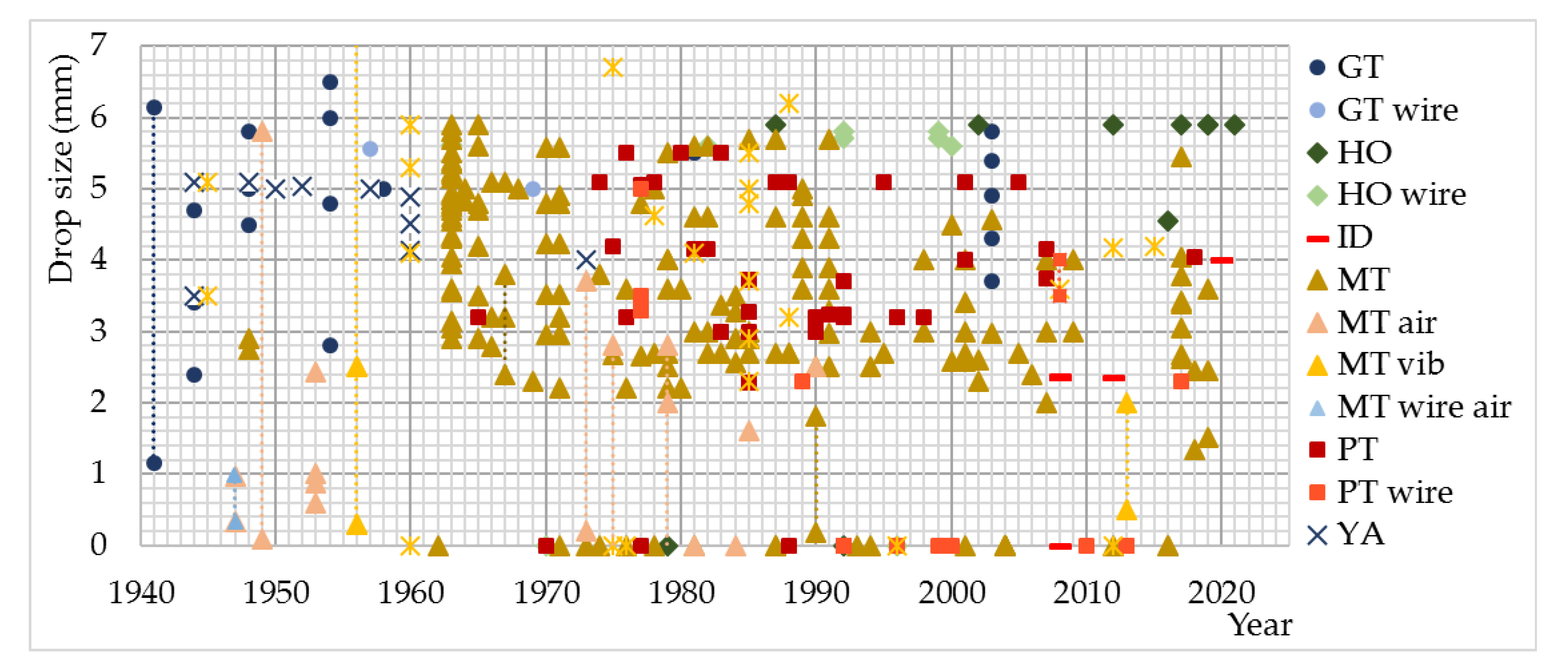
Rainfall simulator drippers are the last in a series of simulator elements, on which end water drops are formed. They are also mentioned in scientific literature as drop formers, drop producers, dripping valves, nuzzles, orifices, and they appear in a form of:
- tubes,
- metal tubes (MT) (hypo needle tubes, hypodermic syringe needles, syringe needles, hypodermic needles with rectangular tip, protruding needles, blunted needles, hypodermic tubing, stainless steel tubing, stainless steel tubes, milled stainless steel tubing, stainless steel capillary tubes, drip needles made from hypodermic tubing, coper tubing, coper tubes, brass tubes) [62,75,135,174,194],
For some drippers the performance is modified by the use of the thin threads of different materials that are placed inside the tubes or holes (80–20 nickel-chromium alloy wire, chromium alloy wire, chromium plated brass wire, 1.016 mm tick chromium alloy wire, stainless steel or plated wire, double 0.2 mm tick nylon thread, 0.55, 0.60, 0.66 mm tick fishing line) (index “wire”) [47,48,89,111,164]. Also, performance is changed by the influence of air flow (index “air”) and vibration (index “vib”), or by the simultaneous influence of air flow and threaded wire on the drops during the simulation [48,59,134,179,181].
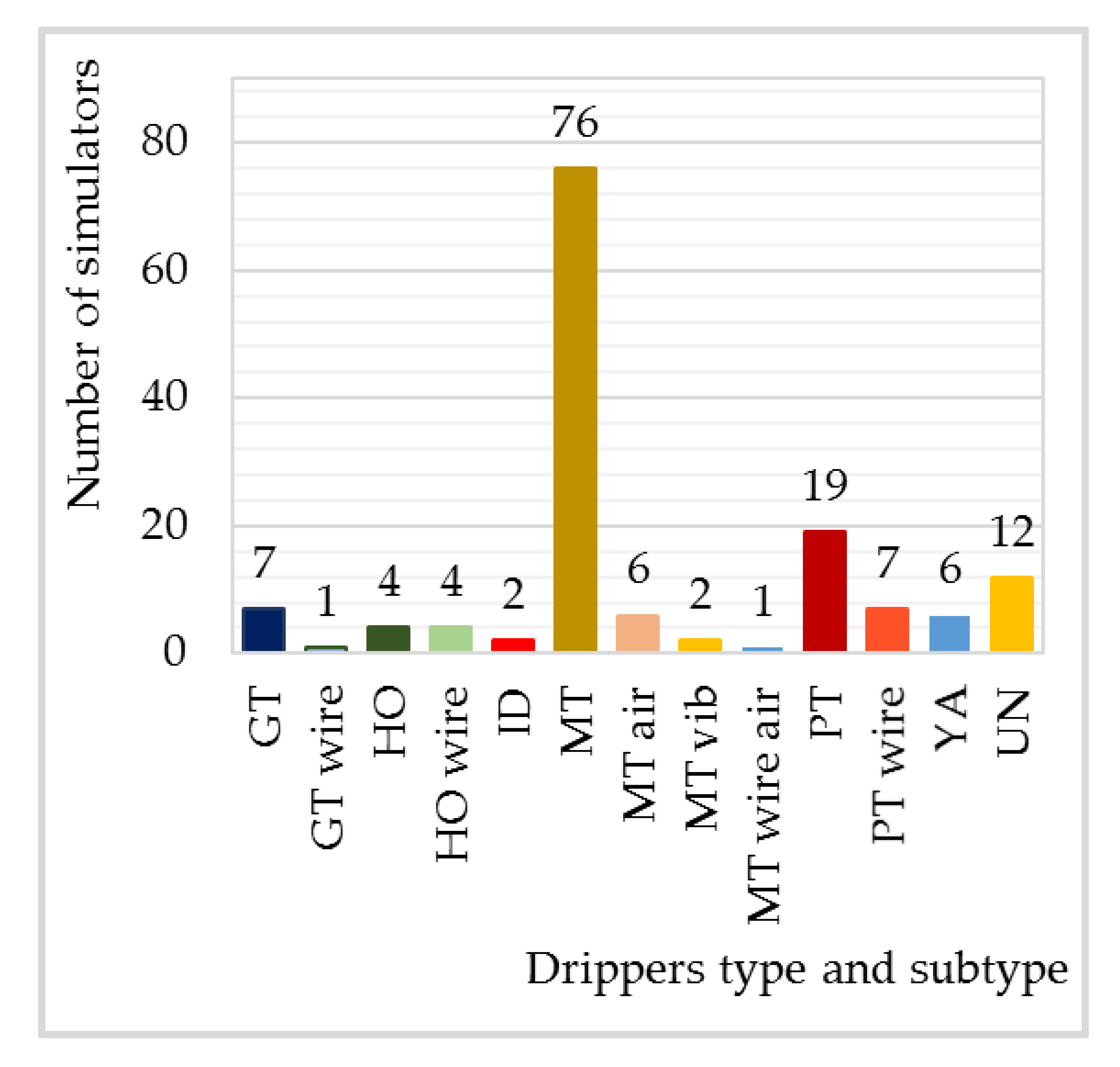
Until the beginning of the 1960’s, drippers in the form of glass tubes, hanging yarn and metal tubes were mostly used. After that, the use of drippers in the form of metal tubes became dominant, and from the second half of the 1970s, drippers in the form of plastic pipes began to be used in large numbers. Later, drippers in the form of holes in water tank with drippers and irrigation drippers were used on several occasions. Also, the use of drippers of unknown type was noted (Figure 13).
By far the most common are drippers in the form of metal pipes, followed by drippers in the form of plastic pipes, the same number of drippers in the form of glass pipes and holes in tanks and the smallest number of drippers in the form of hanging threads and irrigation drippers. Modified performance drippers appear in significantly smaller numbers within their groups and subgroups. In addition to the above, there is a relatively small number of drippers for which no description has been given on the basis of which they could be classified into any of the groups (Figure 14).
4. Conclusions
The paper presents the so far used DRS applied in soil research. Based on the conducted classification, it was determined that a relatively large number of different types DRS and their modified versions were used. Simulators with one dripper were used significantly less than simulators with multiple drippers. The analyzed data provide insight into the most commonly used types or subtypes of simulators, as well as the numerical values of some of the elements that define their design. Research has determined six basic groups of elements that these simulators can consist of: structural support, water tank, water moving mechanism, mechanism of water flow regulation and simulator operation, water tank with drippers and drippers. For each of the groups, the basic purpose and forms in which the elements of the simulator appear are presented. Also, a statistical analysis of the numerical parameters of the elements for which the data was available was carried out. This approach to the analysis of the DRS design should provide insight into the design of simulators used and facilitate the selection of future simulators. In addition to descriptive and numerical descriptions of the basic elements of the simulator according to the classification categories in which the data on them are grouped, a graphic presentation and technical drawings of the simulator in future works should also be provided. This would provide almost all the information necessary for other researchers to make an identical simulator, which should in the future reduce the appearance of simulators of different design and performance. In addition to saving resources during the construction of the simulator, this would bring a step closer to the standardization of rainfall simulators with drippers, which would provide consolidation and comparative analysis of data from different soil research under equal conditions of simulated rainfall. It is important to keep in mind that simulators design and performances are mutually conditional, so to understand the simulator design completely it is needed to analyzed also their performances.
Author Contributions
All authors listed have made a substantial intellectual contribution to the work. All authors have read and agreed to the published version of the manuscript.
Funding
This research was funded by the Ministry of Education, Science and Technological Development of Republic of Serbia (registration number 451-03-68/2022-14/200169).
Acknowledgments
The authors of this paper would like to express their gratitude to the Faculty of Forestry, University of Belgrade, for realization of this research under the scientific project (registration number 451-03-68/2022-14/200169) funded by the Ministry of Education, Science and Technological Development of Republic of Serbia.
Conflicts of Interest
The authors declare no conflict of interest.
References
- Riezebos, T.H.; Seyhan, E. Essential Conditions of Rainfall Simulation for Laboratory Water Erosion Experiments. Earth Surf. Process. 1977, 2, 185–190. [Google Scholar] [CrossRef]
- Meyer, L.D.; Harmon, W.C. Susceptibility of Agricultural Soils to Interrill Erosion. Soil Sci. Soc. Am. J. 1984, 48, 1152–1157. [Google Scholar] [CrossRef]
- Sharpley, A.; Kleinman, P. Effect of Rainfall Simulator and Plot Scale on Overland Flow and Phosphorus Transport. J. Environ. Qual. 2003, 32, 2172–2179. [Google Scholar] [CrossRef] [PubMed] [Green Version]
- Vahabi, J.; Nikkami, D. Assessing Dominant Factors Affecting Soil Erosion Using a Portable Rainfall Simulator. Int. J. Sediment Res. 2008, 23, 376–386. [Google Scholar] [CrossRef]
- Naves, J.; Anta, J.; Suárez, J.; Puertas, J. Development and Calibration of a New Dripper-Based Rainfall Simulator for Large-Scale Sediment Wash-off Studies. Water 2020, 12, 152. [Google Scholar] [CrossRef] [Green Version]
- Bubenzer, G.D.; Meyer, L.D. Simulation of Rainfall and Soils for Laboratory Research. Trans. ASAE 1965, 8, 73. [Google Scholar]
- Moore, I.D.; Hirschi, M.C.; Barfield, B.J. Kentucky Rainfall Simulator. Trans. ASAE 1983, 26, 1085–1089. [Google Scholar] [CrossRef]
- Bowyer-Bower, T.A.S.; Burt, T.P. Rainfall Simulators for Investigating Soil Response to Rainfall. Soil Technol. 1989, 2, 1–16. [Google Scholar] [CrossRef]
- Van Boxel, J.H. Numerical Model for the Fall Speed of Rain Drops in a Rain Fall Simulator. In Workshop on Wind and Water Erosion; University of Amsterdam: Amsterdam, The Netherlands, 1997; pp. 77–85. Available online: https://pure.uva.nl/ws/files/2778495/171269_VanBoxel_1998_GENT_ModelFallSpeedRaindrops.pdf (accessed on 12 October 2022).
- Corona, R.; Wilson, T.; D’Adderio, L.P.; Porcù, F.; Montaldo, N.; Albertson, J. On the Estimation of Surface Runoff through a New Plot Scale Rainfall Simulator in Sardinia, Italy. Procedia Environ. Sci. 2013, 19, 875–884. [Google Scholar] [CrossRef]
- Bryan, R.B. An Improved Rainfall Simulator for Use in Erosion Research. Can. J. Earth Sci. 1970, 7, 1552–1561. [Google Scholar] [CrossRef]
- Navas, A.; Alberto, F.; Machín, J.; Galán, A. Design and Operation of a Rainfall Simulator for Field Studies of Runoff and Soil Erosion. Soil Technol. 1990, 3, 385–397. [Google Scholar] [CrossRef]
- Ogunye, F.O.; Boussabaine, H. Development of a Rainfall Test Rig as an Aid in Soil Block Weathering Assessment. Constr. Build. Mater. 2002, 16, 173–180. [Google Scholar] [CrossRef]
- Sobrinho, A.; Gómez-Macpherson, T.; Gómez, H. A Portable Integrated Rainfall and Overland Flow Simulator. Soil Use Manag. 2008, 24, 163–170. [Google Scholar] [CrossRef]
- Gabrić, O. Eksperimentalno Istraživanje Procesa Na Slivu: Padavine, Oticaj i Erozija Tla; University of Novi Sad: Novi Sad, Serbia, 2014. [Google Scholar]
- Živanović, N.; Rončević, V.; Spasić, M.; Ćorluka, S.; Polovina, S. Construction and Calibration of a Portable Rainfall Simulator Designed for in Situ Researches of Soil Resistance to Erosion. Soil Water Res. 2022, 17, 158–169. [Google Scholar] [CrossRef]
- Chow, V.T.; Harbaugh, T.E. Raindrop Production for Laboratory Watershed Experimentation. J. Geophys. Res. 1965, 70, 6111–6119. [Google Scholar] [CrossRef]
- Meeuwig, R.O. Infiltration and Water Repellency in Granitic Soils; Forest Service: Washington, DC, USA, 1971; Volume 111. [Google Scholar]
- Battany, M.C.; Grismer, M.E. Development of a Portable Field Rainfall Simulator for Use in Hillside Vineyard Runoff and Erosion Studies. Hydrol. Process. 2000, 14, 1119–1129. [Google Scholar] [CrossRef]
- Grismer, M. Standards Vary in Studies Using Rainfall Simulators to Evaluate Erosion. Calif. Agric. 2012, 66, 102–107. [Google Scholar] [CrossRef] [Green Version]
- De Ploey, J.; Moeyersons, J. Runoff Creep of Coarse Debris: Experimental Data and Some Field Observations. Catena 1975, 2, 275–288. [Google Scholar] [CrossRef]
- Imeson, A.C. A Simple Field-Portable Rainfall Simulator for Difficult Terrain. Earth Surf. Process. 1977, 2, 431–436. [Google Scholar] [CrossRef]
- Farres, P.J. The Dynamics of Rainsplash Erosion and the Role of Soil Aggregate Stability. Catena 1987, 14, 119–130. [Google Scholar] [CrossRef]
- Wan, Y.; El-Swaify, S.A. Characterizing Interrill Sediment Size by Partitioning Splash and Wash Processes. Soil Sci. Soc. Am. J. 1998, 62, 430–437. [Google Scholar] [CrossRef]
- Watanabe, H.; Grismer, M.E. Diazinon Transport through Inter-Row Vegetative Filter Strips: Micro-Ecosystem Modeling. J. Hydrol. 2001, 247, 183–199. [Google Scholar] [CrossRef]
- Böker, J.; Zanzinger, H.; Bastian, M.; Németh, E.; Eppel, J. Surface Erosion Control Investigations for a Test Field on a Steep Embankment of German Autobahn A3. 2012. Available online: https://www.researchgate.net/profile/Helmut-Zanzinger/publication/297730907_Surface_erosion_control_investigations_for_a_test_field_on_a_steep_embankment_of_German_Autobahn_A3/links/56e2acf908ae3328e07877e9/Surface-erosion-control-investigations-for-a-test-field-on-a-steep-embankment-of-German-Autobahn-A3.pdf (accessed on 12 October 2022).
- Meyer, L.D. Simulation of Rainfall for Soil Erosion Research. Trans. ASAE 1965, 8, 63–65. [Google Scholar] [CrossRef]
- Mcqueen, I.S.; United States Department of the Interior, Geological Survey. In Development of a Hand Portable Rainfall-Simulator Infiltrometer; 1963; Volume 482. Available online: https://books.google.com.hk/books?hl=en&lr=&id=99l-U1NPJeQC&oi=fnd&pg=PA1&dq=28.%09Mcqueen,+I.S.%3B+United+States+Department+of+the+Interior,+Geological+Survey.+In+Development+of+a+Hand+Portable+Rainfall-Simulator+Infiltrometer%3B+1963%3B+Volume+482.&ots=ZIchDBPdn0&sig=w1F74PXipy-_crmsQjPl7fv544w&redir_esc=y#v=onepage&q&f=false (accessed on 12 October 2022).
- Steinhardt, R.; Hillel, D. A Portable Low—Intensity Rainfall simulator for Field and Laboratory Use. Soil Sci. Soc. Am. J. 1966, 30, 661–663. [Google Scholar] [CrossRef]
- Hall, M.J. A Critique of Methods of Simulating Rainfall. Water Resour. Res. 1970, 6, 1104–1114. [Google Scholar] [CrossRef]
- Meyer, L.D.; Harmon, W.C. Multiple-Intensity Rainfall Simulator for Erosion Research on Row Sideslopes. Trans. ASAE 1979, 22, 100–0103. [Google Scholar] [CrossRef]
- Onstad, C.A.; Radke, J.K.; Young, R.A. Outdoor Portable Rainfall Erosion Laboratory. In Erosion and Sediment Transport Measurement: Symposium; IAHS Publication: Wallingford, UK, 1981. [Google Scholar]
- Parr, J.F.; Bertrand, A.R. Water Infiltration into Soils. In Advances in Agronomy; Elsevier: Amsterdam, The Netherlands, 1960; pp. 311–363. [Google Scholar]
- Mutchler, C.K.; Hermsmeier, L.F. A Review of Rainfall Simulators. Trans. ASAE 1965, 8, 67–68. [Google Scholar]
- Yakubu, M.L.; Yusop, Z. Adaptability of Rainfall Simulators as a Research Tool on Urban Sealed Surfaces—A Review. Hydrol. Sci. J. 2017, 62, 996–1012. [Google Scholar] [CrossRef]
- Ngasoh, F.G.; Mbajiorgu, C.C.; Kamai, M.B.; Okoro, G.O. A Revisit of Rainfall Simulator as a Potential Tool for Hydrological Research; Intech Open: London, UK, 2020. [Google Scholar]
- Amerman, C.R. Proceedings of the Rainfall Simulator Workshop: Tucson, Arizona; Western Region. 1979. Available online: https://books.google.co.kr/books?hl=en&lr=&id=-DlDble2vPsC&oi=fnd&pg=PR10&dq=37.%09Amerman,+C.R.+Proceedings+of+the+Rainfall+Simulator+Workshop:+Tucson,+Arizona%3B+Western+Region:+1979.&ots=EfI0yi30Ef&sig=FHwt-mgWeTSikAH1gbX7IHV2e9c&redir_esc=y#v=onepage&q&f=false (accessed on 12 October 2022).
- Cerdà, A. Simuladores de Lluvia y Su Aplicación a La Geomorfología: Estado de La Cuestión. Cuad. De Investig. Geográfica Geogr. Res. Lett. 1999, 25, 45–84. [Google Scholar] [CrossRef] [Green Version]
- Tricker, A.S. The Design of a Portable Rainfall Simulator Infiltrometer. J. Hydrol. 1979, 41, 143–147. [Google Scholar] [CrossRef]
- Roth, C.H.; Meyer, B.; Frede, H.-G. A Portable Rainfall Simulator for Studying Factors Affecting Runoff, Infiltration and Soil Loss. Catena 1985, 12, 79–85. [Google Scholar] [CrossRef]
- Brakensiek, D.L.; Rawls, W.J.; Hamon, W.R. Application of an Infiltrometer System for Describing Infiltration into Soils. Trans. ASAE 1979, 22, 320–325. [Google Scholar] [CrossRef]
- Joel, A.; Messing, I. Infiltration Rate and Hydraulic Conductivity Measured with Rainfall simulator and Disc Permeameter on Sloping Arid Land. Arid. Land Res. Manage. 2001, 15, 371–384. [Google Scholar] [CrossRef]
- Healy, M.G.; Fenton, O.; Cummins, E.; Clarke, R.; Peyton, D.; Fleming, G.; Cormican, M. Health and Water Quality Impacts Arising from Land Spreading of Biosolids. Environ. Prot. Agency Res. Rep. 2017, 200. [Google Scholar]
- Mutchler, C.K. Using the Drift of Waterdrops during Fall for Rainfall Simulator Design. J. Geophys. Res. 1965, 70, 3899–3902. [Google Scholar] [CrossRef]
- Bhardwaj, A.; Singh, R. Development of a Portable Rainfall Simulator Infiltrometer for Infiltration, Runoff and Erosion Studies. Agric. Water Manag. 1992, 22, 235–248. [Google Scholar] [CrossRef]
- Harden, C.P. Rainfall Response of Degraded Soil Following Reforestation in the Copper Basin, Tennessee, USA. Environ. Manage. 2000, 26, 163–174. [Google Scholar] [CrossRef]
- Summer, R.M. Field and Laboratory Studies on Alpine Soil Erodibility, Southern Rocky Mountains, Colorado. Earth Surf. Process. 2007, 7, 253–266. [Google Scholar] [CrossRef]
- Lane, W.R. A Microburette for Producing Small Liquid Drops of Known Size. J. Sci. Instrum. 1947, 24, 98–101. [Google Scholar] [CrossRef]
- Blackburn, W.H. Simulated Rainfall Studies of Selected Plant Communities and Soils in Five Rangeland Watersheds of Nevada. Ph.D. Thesis, University of Nevada, Reno, Reno, NV, USA, 1973. [Google Scholar]
- Munn, J.R.; Huntington, G.L. A Portable Rainfall Simulator for Erodibility and Infiltration Measurements on Rugged Terrain. Soil Sci. Soc. Am. J. 1976, 40, 622–624. [Google Scholar] [CrossRef]
- Malekuti, A.; Gifford, G.F.; Malekuti, A.; Gifford, G.F. Natural Vegetation as a Source of Diffuse Salt within the Colorado River Basin 1. Jawra J. Am. Water Resour. Assoc. 1978, 14, 195–205. [Google Scholar] [CrossRef]
- Ryżak, M.; Bieganowski, A. Using the Image Analysis Method for Describing Soil Detachment by a Single Water Drop Impact. Sensors 2012, 12, 11527–11543. [Google Scholar] [CrossRef] [Green Version]
- Nampulá, J.L.C.; Lara, C.M.G.; Medinilla, E.E.; Herrera, R.G.; Toledo, P.V.; Sánchez, R.A.V. Diseño y Calibración de Un Simulador Automático de Lluvia. Espac. I+D Innovación Más Desarro 2016, 5, 23–37. [Google Scholar] [CrossRef]
- Israelsen, C.E.; Israelsen, E.K.; Fletcher, J.E.; Fifield, J.S.; Canfield, R.V. Erosion Control Product Testing. 1979. Available online: https://digitalcommons.usu.edu/water_rep/367/ (accessed on 12 October 2022).
- Savat, J. Work Done by Splash: Laboratory Experiments. Earth Surf. Process. 1981, 6, 275–283. [Google Scholar] [CrossRef]
- Thompson, A.L.; James, L.G. Water Droplet Impact and Its Effect on Infiltration. Trans. ASAE 1985, 28, 1506–1510. [Google Scholar] [CrossRef]
- Commandeur, P.R. Soil Erosion Studies Using Rainfall Simulation on Forest Harvested Areas in British Columbia. In Proceedings of the International Symposium on Erosion, Debris Flows and Environment in Mountain Regions, Chengdu, China, 5–9 July 1992; IAHS Publication: Oxfordshire, UK, 1992; pp. 21–23. [Google Scholar]
- Wang, L.; Fang, N.F.; Yue, Z.J.; Shi, Z.H.; Hua, L. Raindrop Size and Flow Depth Control Sediment Sorting in Shallow Flows on Steep Slopes. Water Resour. Res. 2018, 54, 9978–9995. [Google Scholar] [CrossRef]
- Huang, J.; Wu, P.; Zhao, X. Effects of Rainfall Intensity, Underlying Surface and Slope Gradient on Soil Infiltration under Simulated Rainfall Experiments. Catena 2013, 104, 93–102. [Google Scholar] [CrossRef]
- Andersen, C.T.; Foster, I.D.L.; Pratt, C.J. The Role of Urban Surfaces (Permeable Pavements) in Regulating Drainage and Evaporation: Development of a Laboratory Simulation Experiment. Hydrol. Process. 1999, 13, 597–609. [Google Scholar] [CrossRef]
- Fernández-Gálvez, J.; Barahona, E.; Mingorance, M.D. Measurement of Infiltration in Small Field Plots by a Portable Rainfall Simulator: Application to Trace-Element Mobility. Water Air Soil Pollut. 2008, 191, 257–264. [Google Scholar] [CrossRef]
- Mutchler, C.K.; Moldenhauer, W.C. Applicator for Laboratory Rainfall Simulator. Trans. ASAE 1963, 6, 220–222. [Google Scholar]
- Blackburn, W.H.; Meeuwig, R.O.; Skau, C.M. A Mobile Infiltrometer for Use on Rangeland. J. Range Manag. 1974, 27, 322. [Google Scholar] [CrossRef]
- Epstein, E.; Grant, W.J. TB22: Design, Construction and Calibration of a Laboratory Rainfall Simulator. In Technical Bulletins of the Maine Agricultural & Forest Experiment Station. 1966. Available online: https://scholar.google.com.hk/scholar?hl=en&as_sdt=0%2C5&q=64.%09Blackburn%2C+W.H.%3B+Meeuwig%2C+R.O.%3B+Skau%2C+C.M.+A+Mobile+Infiltrometer+for+Use+on+Rangeland.+J.+Range+Manag.+1974%2C+27%2C+322.+https%3A%2F%2Fdoi.org%2F10.2307%2F3896835.&btnG= (accessed on 12 October 2022).
- Riezebos, H.T.; Epema, G.F. Drop Shape and Erosivity Part II: Splash Detachment, Transport and Erosivity Indices. Earth Surf. Process. 1985, 10, 69–74. [Google Scholar] [CrossRef]
- Lu, J.-Y.; Lee, J.-J.; Lu, T.-F.; Hong, J.-H. Experimental Study of Extreme Shear Stress for Shallow Flow under Simulated Rainfall. Hydrol. Process. 2009, 23, 1660–1667. [Google Scholar] [CrossRef]
- Ao, C.; Yang, P.; Zeng, W.; Chen, W.; Xu, Y.; Xu, H.; Zha, Y.; Wu, J.; Huang, J. Impact of Raindrop Diameter and Polyacrylamide Application on Runoff, Soil and Nitrogen Loss via Raindrop Splashing. Geoderma 2019, 353, 372–381. [Google Scholar] [CrossRef]
- Farres, P.J.; Cousen, S.M. An Improved Method of Aggregate Stability Measurement. Earth Surf. Process. 1985, 10, 321–329. [Google Scholar] [CrossRef]
- Heilig, A.; DeBruyn, D.; Walter, M.T.; Rose, C.W.; Parlange, J.-Y.; Steenhuis, T.S.; Sander, G.C.; Hairsine, P.B.; Hogarth, W.L.; Walker, L.P. Testing a Mechanistic Soil Erosion Model with a Simple Experiment. J. Hydrol. 2006, 317, 171–172. [Google Scholar] [CrossRef]
- Fu, Y.; Li, G.-L.; Zheng, T.-H.; Li, B.-Q.; Zhang, T. Splash Detachment and Transport of Loess Aggregate Fragments by Raindrop Action. Catena 2017, 150, 154–160. [Google Scholar] [CrossRef]
- Ayoubi, S.; Mokhtari, J.; Mosaddeghi, M.R.; Zeraatpisheh, M. Erodibility of Calcareous Soils as Influenced by Land Use and Intrinsic Soil Properties in a Semiarid Region of Central Iran. Environ. Monit. Assess. 2018, 190, 192. [Google Scholar] [CrossRef]
- Sharma, P.P.; Gupta, S.C. Sand Detachment by Single Raindrops of Varying Kinetic Energy and Momentum. Soil Sci. Soc. Am. J. 1989, 53, 1005–1010. [Google Scholar] [CrossRef]
- Römkens, M.J.M.; Glenn, L.F.; Nelson, D.W.; Roth, C.B. A Laboratory Rainfall Simulator for Infiltration and Soil Detachment Studies1. Soil Sci. Soc. Am. J. 1975, 39, 158. [Google Scholar] [CrossRef]
- Ran, Q.; Su, D.; Li, P.; He, Z. Experimental Study of the Impact of Rainfall Characteristics on Runoff Generation and Soil Erosion. J. Hydrol. 2012, 424–425, 99–111. [Google Scholar] [CrossRef]
- Palmer, R.S. An Apparatus for Forming Waterdrops; US Department of Agriculture: Washington, DC, USA, 1962; Volume 61. [Google Scholar]
- Dunkerley, D.L. Intra-Storm Evaporation as a Component of Canopy Interception Loss in Dryland Shrubs: Observations from Fowlers Gap, Australia. Hydrol. Process. 2008, 22, 1985–1995. [Google Scholar] [CrossRef]
- Robinson, D.A.; Naghizadeh, R. The Impact of Cultivation Practice and Wheelings on Runoff Generation and Soil Erosion on the South Downs: Some Experimental Results Using Simulated Rainfall. Soil Use Manag. 1992, 8, 151–156. [Google Scholar] [CrossRef]
- Xiao, H.; Liu, G.; Abd-Elbasit, M.A.M.; Zhang, X.C.; Liu, P.L.; Zheng, F.L.; Zhang, J.Q.; Hu, F.N. Effects of Slaking and Mechanical Breakdown on Disaggregation and Splash Erosion: Effects of Splash Erosion on Aggregate Breakdown. Eur. J. Soil Sci. 2017, 68, 797–805. [Google Scholar] [CrossRef]
- Rose, C.W. Soil Detachment Caused by Rainfall. Soil Sci. 1960, 89, 28–35. [Google Scholar] [CrossRef]
- Regmi, T.P.; Thompson, A.L. Rainfall Simulator for Laboratory Studies. Appl. Eng. Agric. 2000, 16, 641–647. [Google Scholar] [CrossRef]
- Hignett, C.T.; Gusli, S.; Cass, A.; Besz, W. An Automated Laboratory Rainfall Simulation System with Controlled Rainfall Intensity, Raindrop Energy and Soil Drainage. Soil Technol. 1995, 8, 31–42. [Google Scholar] [CrossRef]
- Terry, J.P.; Shakesby, R.A. Soil Hydrophobicity Effects on Rainsplash: Simulated Rainfall and Photographic Evidence. Earth Surf. Process. 1993, 18, 519–525. [Google Scholar] [CrossRef]
- Cousen, S.M.; Farres, P.J. The Role of Moisture Content in the Stability of Soil Aggregates from a Temperate Silty Soil to Raindrop Impact. Catena 1984, 11, 313–320. [Google Scholar] [CrossRef]
- Walker, P.H.; Hutka, J.; Moss, A.J.; Kinnell, P.I.A. Use of a Versatile Experimental System for Soil Erosion Studies. Soil Sci. Soc. Am. J. 1977, 41, 610–612. [Google Scholar] [CrossRef]
- Bubenzer, G.D.; Jones, B.A. Drop Size and Impact Velocity Effects on the Detachment of Soils Under Simulated Rainfall. Trans. ASAE 1971, 14, 625–628. [Google Scholar]
- Singh, R.; Panigrahy, N.; Philip, G. Modified Rainfall Simulator Infiltrometer for Infiltration, Runoff and Erosion Studies. Agric. Water Manag. 1999, 41, 167–175. [Google Scholar] [CrossRef]
- Guerrant, D.G.; Miller, W.W.; Mahannah, C.N.; Narayanan, R. Infiltration Evaluation of Four Mechanical Rainfall Simulation Techniques in Sierra Nevada Watersheds 1. Jawra J. Am. Water Resour. Assoc. 1990, 26, 127–134. [Google Scholar] [CrossRef]
- Gao, B.; Walter, M.T.; Steenhuis, T.S.; Parlange, J.-Y.; Nakano, K.; Rose, C.W.; Hogarth, W.L. Investigating Ponding Depth and Soil Detachability for a Mechanistic Erosion Model Using a Simple Experiment. J. Hydrol. 2003, 277, 116–124. [Google Scholar] [CrossRef]
- Foster, I.D.L.; Fullen, M.A.; Brandsma, R.T.; Chapman, A.S. Drip-Screen Rainfall Simulators for Hydro-and Pedo-Geomorphological Research: The Coventry Experience. Earth Surf. Process. Landf. 2000, 25, 691–707. [Google Scholar] [CrossRef]
- Wan, Y.; El-Swaify, S.A.; Sutherland, R.A. Partitioning Interrill Splash and Wash Dynamics: A Novel Laboratory Approach. Soil Technol. 1996, 9, 55–69. [Google Scholar] [CrossRef]
- Ellison, W.D.; Pomerene, W.H. A Rainfall Applicator. Agric. Eng. 1944, 25. [Google Scholar]
- Goodman, L.J. Erosion Control in Engineering Works. Agric. Eng. 1952, 33, 155–157. [Google Scholar]
- Barnes, O.K.; Costel, G. A Mobile Infiltrometer 1. Agron. J. 1957, 49, 105–107. [Google Scholar] [CrossRef]
- Maore, J.M.; Mihara, M. Development of Portable Artificial Rainfall Simulator for Evaluating Sustainable Farming in Kenya. Int. J. Environ. Rural. Dev. 2017, 8, 27–33. [Google Scholar]
- Shainberg, I.; Mamedov, A.I.; Levy, G.J. Role of Wetting Rate and Rain Energy in Seal Formation and Erosion 1. Soil Sci. 2003, 168, 54–62. [Google Scholar] [CrossRef]
- Parlak, M. Determination of Soil Erosion over Different L and Uses by Mini Rainfall Simulator. J. Food Agric. Environ. 2012, 10, 929–933. [Google Scholar]
- Roth, C.H.; Helming, K. Dynamics of Surface Sealing, Runoff Formation and Interrill Soil Loss as Related to Rainfall Intensity, Microrelief and Slope. Z. Für Pflanz. Und Bodenkd. 1992, 155, 209–216. [Google Scholar] [CrossRef]
- Thompson, A.L.; Ghidey, F.; Regmi, T.P. Raindrop Energy Effects on Chemical and Sediment Transport. Trans. ASAE 2001, 44, 835. [Google Scholar] [CrossRef]
- Clarke, M.A.; Walsh, R.P.D. A Portable Rainfall Simulator for Field Assessment of Splash and Slopewash in Remote Locations. Earth Surf. Process. 2007, 32, 2052–2069. [Google Scholar] [CrossRef]
- Bombino, G.; Denisi, P.; Gómez, J.; Zema, D. Water Infiltration and Surface Runoff in Steep Clayey Soils of Olive Groves under Different Management Practices. Water 2019, 11, 240. [Google Scholar] [CrossRef] [Green Version]
- Kamphorst, A. A Small Rainfall Simulator for the Determination of Soil Erodibility. Neth. J. Agric. Sci. 1987, 35, 407–415. [Google Scholar] [CrossRef]
- Eijkelkamp—Laboratory Equipment. Available online: https://en.eijkelkamp (accessed on 7 July 2018).
- Bisal, F. The Effect of Raindrop Size and Impact Velocity on Sand-Splash. Can. J. Soil Sci. 1960, 40, 242–245. [Google Scholar] [CrossRef] [Green Version]
- Woodburn, R. The Effect of Structural Condition on Soil Detachment by Raindrop Impact. Agric. Eng. 1948, 29, 154–156. [Google Scholar]
- Osborn, B. Measuring Soil Splash and Protective Value of Cover on Range Land: Methods and Equipment Used in Range Cover Evaluations in Texas and Oklahoma; US Department of Agriculture: Washington, DC, USA, 1949. [Google Scholar]
- Yamamoto, T.; Anderson, H.W. Splash Erosion Related to Soil Erodibility Indexes and Other Forest Soil Properties in Hawaii. Water Resour. Res. 1973, 9, 336–345. [Google Scholar] [CrossRef]
- Ekern, P.C., Jr.; Muckenhirn, R.J. Water Drop Impact as a Force in Transporting Sand. Soil Sci. Soc. Am. J. 1948, 12, 441–444. [Google Scholar] [CrossRef] [Green Version]
- Mcintyre, D.S. Permeability Measurements of Soil Crusts Formed by Raindrop Impact. Soil Sci. 1958, 85, 185–189. [Google Scholar] [CrossRef]
- Mcintyre, D.S. Soil Splash and the Formation of Surface Crusts by Raindrop Impact. Soil Sci. 1958, 85, 261–266. [Google Scholar] [CrossRef]
- Rasbash, D.J. The Production of Water Spray of Uniform Drop Size by a Battery of Hypodermic Needles. J. Sci. Instrum. 1953, 30, 189–192. [Google Scholar] [CrossRef]
- Adams, J.E.; Kirkham, D.; Nielsen, D.R. A Portable Rainfall-Simulator Infiltrometer and Physical Measurements of Soil in Place. Soil Sci. Soc. Am. J. 1957, 21, 473–477. [Google Scholar] [CrossRef]
- Moldenhauer, W.C.; Kemper, W.D. Interdependence of Water Drop Energy and Clod Size on Infiltration and Clod Stability. Soil Sci. Soc. Am. J. 1969, 33, 297–301. [Google Scholar] [CrossRef]
- Selby, M.J. Design of a Hand-Portable Rainfall-Simulating Infiltrometer, with Trial Results from the Otutira Catchment. J. Hydrol. 1970, 117–132. [Google Scholar]
- Moldenhauer, W.C.; Long, D.C. Influence of Rainfall Energy on Soil Loss and Infiltration Rates: I. Effect over a Range of Texture. Soil Sci. Soc. Am. J. 1964, 28, 813–817. [Google Scholar] [CrossRef]
- Moldenhauer, W.C.; Koswara, J. Effect of Initial Clod Size on Characteristics of Splash and Wash Erosion1. Soil Sci. Soc. Am. J. 1968, 32, 875. [Google Scholar] [CrossRef]
- Gabriels, D.; Moldenhauer, W.C. Size Distribution of Eroded Material from Simulated Rainfall: Effect over a Range of Texture. Soil Sci. Soc. Am. J. 1978, 42, 954–958. [Google Scholar] [CrossRef]
- Norton, L.D. Micromorphological Study of Surface Seals Developed under Simulated Rainfall. Geoderma 1987, 40, 127–140. [Google Scholar] [CrossRef]
- Black, P.E. Runoff from Watershed Models. Water Resour. Res. 1970, 6, 465–477. [Google Scholar] [CrossRef]
- Thurow, T.L.; Blackburn, W.H.; Warren, S.D.; Taylor, C.A. Rainfall Interception by Midgrass, Shortgrass, and Live Oak Mottes. J. Range Manag. 1987, 40, 455. [Google Scholar] [CrossRef]
- Bissonnais, Y.L.; Singer, M.J. ECrusting, Runoff, and Erosion Response to Soil Water Content and Successive Rainfalls. Soil Sci. Soc. Am. J. 1992, 56, 1898–1903. [Google Scholar] [CrossRef]
- Ahuja, L.R.; Lehman, O.R.; Sharpley, A.N. Bromide and Phosphate in Runoff Water from Shaped and Cloddy Soil Surfaces. Soil Sci. Soc. Am. J. 1983, 47, 746–748. [Google Scholar] [CrossRef]
- Ahuja, L.R.; Lehman, O.R. The Extent and Nature of Rainfall—Soil Interaction in the Release of Soluble Chemicals to Runoff. J. Environ. Qual. 1983, 12, 34–40. [Google Scholar] [CrossRef]
- Ahuja, L.R. Modeling Soluble Chemical Transfer to Runoff with Rainfall Impact as a Diffusion Process. Soil Sci. Soc. Am. J. 1990, 54, 312–321. [Google Scholar] [CrossRef]
- Moore, D.C.; Singer, M.J. Crust Formation Effects on Soil Erosion Processes. Soil Sci. Soc. Am. J. 1990, 54, 1117–1123. [Google Scholar] [CrossRef]
- Guerrant, D.G.; Miller, W.W.; Mahannah, C.N.; Narayanan, R. Site—Specific Erosivity Evaluation of a Sierra Nevada Forested Watershed Soil. J. Environ. Qual. 1991, 20, 396–402. [Google Scholar] [CrossRef]
- Naslas, G.D.; Miller, W.W.; Gifford, G.F.; Fernandez, G.C.J. Effects of Soil Type, Plot Condition, and Slope on Runoff and Interrill Erosion of Two Soils in the Lake Tahoe Basin 1. Jawra J. Am. Water Resour. Assoc. 1994, 30, 319–328. [Google Scholar] [CrossRef]
- Wood, M.K.; Blackburn, W.H. Grazing Systems: Their Influence on Infiltration Rates in the Rolling Plains of Texas. J. Range Manag. 1981, 34, 331. [Google Scholar] [CrossRef]
- Wilson, J.P.; Seney, J.P. Erosional Impact of Hikers, Horses, Motorcycles, and off-Road Bicycles on Mountain Trails in Montana. Mt. Res. Dev. 1994, 14, 77–88. [Google Scholar] [CrossRef]
- Sutherland, R.A.; Wan, Y.; Ziegler, A.D.; Lee, C.-T.; El-Swaify, S.A. Splash and Wash Dynamics: An Experimental Investigation Using an Oxisol. Geoderma 1996, 69, 85–103. [Google Scholar] [CrossRef]
- Will, G.L. Infiltration under a Rainfall Simulator. 1973. [Google Scholar]
- Jeppson, R.W.; Rawls, W.J.; Hamon, W.R.; Schreiber, D.L. Use of Axisymmetric Infiltration Model and Field Data to Determine Hydraulic Properties of Soils. Water Resour. Res. 1975, 11, 127–138. [Google Scholar] [CrossRef]
- Young, R.A. A Method of Measuring Aggregate Stability under Waterdrop Impact. Trans. ASAE 1984, 27, 1351–1354. [Google Scholar] [CrossRef]
- Freebairn, D.M.; Gupta, S.C. Microrelief, Rainfall and Cover Effects on Infiltration. Soil Tillage Res. 1990, 16, 307–327. [Google Scholar] [CrossRef]
- Schultz, J.P.; Jarrett, A.R.; Hoover, J.R. Detachment and Splash of a Cohesive Soil by Rainfall. Trans. ASAE 1985, 28, 1878–1884. [Google Scholar] [CrossRef]
- Kinnell, P.I.A. Splash Erosion: Some Observations on the Splash-Cup Technique. Soil Sci. Soc. Am. J. 1974, 38, 657–660. [Google Scholar] [CrossRef]
- Walker, P.H.; Kinnell, P.I.A.; Green, P. Transport of a Noncohesive Sandy Mixture in Rainfall and Runoff Experiments. Soil Sci. Soc. Am. J. 1978, 42, 793–801. [Google Scholar] [CrossRef]
- Aston, A.R. Rainfall Interception by Eight Small Trees. J. Hydrol. 1979, 42, 383–396. [Google Scholar] [CrossRef]
- Moss, A.J.; Walker, P.H.; Hutka, J. Raindrop-Stimulated Transportation in Shallow Water Flows: An Experimental Study. Sediment. Geol. 1979, 22, 165–184. [Google Scholar] [CrossRef]
- Kinnell, P.I.A. Laboratory Studies on the Effect of Drop Size on Splash Erosion. J. Agric. Eng. Res. 1982, 27, 431–439. [Google Scholar] [CrossRef]
- Moss, A.J.; Green, P. Movement of Solids in Air and Water by Raindrop Impact. Effects of Drop-Size and Water-Depth Variations. Soil Res. 1983, 21, 257. [Google Scholar] [CrossRef]
- Herwitz, S.R. Interception Storage Capacities of Tropical Rainforest Canopy Trees. J. Hydrol. 1985, 77, 237–252. [Google Scholar] [CrossRef]
- Moss, A.J.; Green, T.W. Erosive Effects of the Large Water Drops (Gravity Drops) That Fall from Plants. Soil Res. 1987, 25, 9. [Google Scholar] [CrossRef]
- Kinnell, P.I.A. The Influence of Flow Discharge on Sediment Concentrations in Raindrop Induced Flow Transport. Soil Res. 1988, 26, 575. [Google Scholar] [CrossRef]
- Moss, A.J. Effects of Flow Velocity Variation on Rain Driven Transportation and the Role of Rain Impact in the Movement of Solids. Soil Res. 1988, 26, 443. [Google Scholar] [CrossRef]
- Kinnell, P.I.A. Particle Travel Distances and Bed and Sediment Compositions Associated with Rain-Impacted Flows. Earth Surf. Process. 2001, 26, 749–758. [Google Scholar] [CrossRef]
- Foley, J.L.; Silburn, D.M. Hydraulic Properties of Rain Impact Surface Seals on Three Clay Soils-Influence of Raindrop Impact Frequency and Rainfall Intensity during Steady State. Soil Res. 2002, 40, 1069–1083. [Google Scholar] [CrossRef]
- Kinnell, P.I.A. Sediment Transport by Medium to Large Drops Impacting Flows at Subterminal Velocity. Soil Sci. Soc. Am. J. 2005, 69, 902–905. [Google Scholar] [CrossRef]
- De Ploey, J.; Mücher, H.J. A Consistency Index and Rainwash Mechanisms on Belgian Loamy Soils. Earth Surf. Process. 1981, 6, 319–330. [Google Scholar] [CrossRef]
- De Ploey, J. A Stemflow Equation for Grasses and Similar Vegetation. Catena 1982, 9, 139–152. [Google Scholar] [CrossRef]
- Wierda, A.; Veen, A.W.L. A Rainfall Simulator Study of Infiltration into Arable Soils. Agric. Water Manag. 1992, 21, 119–135. [Google Scholar] [CrossRef]
- Gabriels, D.; De Boodt, M. Erosion Reduction Factors for Chemically Treated Soils: A Laboratory Experiment. In SSSA Special Publications; Soil Science Society of America: Madison, WI, USA, 1975; pp. 95–102. [Google Scholar]
- Houk, D.; Green, T. A Note on Surface Waves Due to Rain. J. Geophys. Res. 1976, 81, 4482–4484. [Google Scholar] [CrossRef]
- Green, T.; Houk, D.F. The Mixing of Rain with Near-Surface Water. J. Fluid Mech. 1979, 90, 569. [Google Scholar] [CrossRef]
- West, N.E.; Gifford, G.F. Rainfall Interception by Cool-Desert Shrubs. J. Range Manag. 1976, 29, 171. [Google Scholar] [CrossRef]
- Chevone, B.I.; Yang, Y.S.; Winner, W.E.; Storks-Cotter, I.; Long, S.J. A Rainfall Simulator for Laboratory Use in Acidic Precipitation Studies. J. Air Pollut. Control Assoc. 1984, 34, 355–359. [Google Scholar] [CrossRef]
- Roth, C.H.; Joschko, M. A Note on the Reduction of Runoff from Crusted Soils by Earthworm Burrows and Artificial Channels. Z. Pflanzenernaehr. Bodenkd. 1991, 154, 101–105. [Google Scholar] [CrossRef]
- Carrà, B.G.; Bombino, G.; Denisi, P.; Plaza-Àlvarez, P.A.; Lucas-Borja, M.E.; Zema, D.A. Water Infiltration after Prescribed Fire and Soil Mulching with Fern in Mediterranean Forests. Hydrology 2021, 8, 95. [Google Scholar] [CrossRef]
- Hlavčová, K.; Danáčová, M.; Kohnová, S.; Szolgay, J.; Valent, P.; Výleta, R. Estimating the Effectiveness of Crop Management on Reducing Flood Risk and Sediment Transport on Hilly Agricultural Land—A Myjava Case Study, Slovakia. Catena 2019, 172, 678–690. [Google Scholar] [CrossRef]
- Danacova, M. The Impact of Slope Gradients on the Generation of Surface Runoff in Laboratory Conditions. In Proceedings of the 17th International Multidisciplinary Scientific GeoConference SGEM2017, Water Resources, Forest, Marine and Ocean Ecosystems, Vienna, Austria, 27–29 November 2017. [Google Scholar]
- Cerdà, A.; García-Fayos, P. The Influence of Seed Size and Shape on Their Removal by Water Erosion. Catena 2002, 48, 293–301. [Google Scholar] [CrossRef]
- Boers, T.M.; van Deurzen, F.J.M.P.; Eppink, L.A.A.J.; Ruytenberg, R.E. Comparison of Infiltration Rates Measured with an Infiltrometer, a Rainulator and a Permeameter for Erosion Research in SE Nigeria. Soil Technol. 1992, 5, 13–26. [Google Scholar] [CrossRef]
- Dalgleish, H.Y.; Foster, I.D.L. 137Cs Losses from a Loamy Surface Water Gleyed Soil (Inceptisol); a Laboratory Simulation Experiment. Catena 1996, 26, 227–245. [Google Scholar] [CrossRef]
- Mohr, C.; Anton, H. Design and Application of a Drip-Type Rainfall Simulator Adapted to Steep Topography and Low Intensity-Rainfall Characteristics in the Coastal Range of Southern Chile. In Proceedings of the EGU General Assembly Conference Abstracts, Vienna, Austria, 9–24 April; 2009. [Google Scholar]
- Mohr, C.H.; Coppus, R.; Iroumé, A.; Huber, A.; Bronstert, A. Runoff Generation and Soil Erosion Processes after Clear Cutting: Runoff and Erosion After Clear Cutting. J. Geophys. Res. Earth Surf. 2013, 118, 814–831. [Google Scholar] [CrossRef]
- Levin, J.; Ben-Hur, M.; Gal, M.; Levy, G.J. Rain Energy and Soil Amendments Effects on Infiltration and Erosion of Three Different Soil Types. Soil Res. 1991, 29, 455. [Google Scholar] [CrossRef]
- Mohanty, S.; Singh, R. Determination of Soil Hydrologic Properties under Simulated Rainfall Condition. Agric. Water Manag. 1996, 29, 267–281. [Google Scholar] [CrossRef]
- Agassi, M.; Bloem, D.; Ben-Hur, M. Effect of Drop Energy and Soil and Water Chemistry on Infiltration and Erosion. Water Resour. Res. 1994, 30, 1187–1193. [Google Scholar] [CrossRef]
- Heathwaite, A.L.; Johnes, P.J. Contribution of Nitrogen Species and Phosphorus Fractions to Stream Water Quality in Agricultural Catchments. Hydrol. Process. 1996, 10, 971–983. [Google Scholar] [CrossRef]
- Lu, J.-Y.; Chen, J.-Y.; Chang, F.-H.; Lu, T.-F. Characteristics of Shallow Rain-Impacted Flow over Smooth Bed. J. Hydraul. Eng. 1998, 124, 1242–1252. [Google Scholar] [CrossRef]
- Lu, J.-Y.; Chen, J.-Y.; Hong, J.-H.; Lu, T.-F.; Liu, C.-S. Turbulence Intensities of Shallow Rain-Impacted Flow over Rough Bed. J. Hydraul. Eng. 2001, 127, 881–886. [Google Scholar] [CrossRef]
- Dimoyiannis, D.G.; Valmis, S.; Vyrlas, P. A Rainfall Simulation Study of Erosion of Some Calcareous Soils. Glob. Nest 2001, 3, 179–183. [Google Scholar]
- Gao, B.; Todd Walter, M.; Steenhuis, T.S.; Hogarth, W.L.; Parlange, J.-Y. Rainfall Induced Chemical Transport from Soil to Runoff: Theory and Experiments. J. Hydrol. 2004, 295, 291–304. [Google Scholar] [CrossRef]
- Gao, B.; Walter, M.T.; Steenhuis, T.S.; Parlange, J.-Y.; Richards, B.K.; Hogarth, W.L.; Rose, C.W. Investigating Raindrop Effects on Transport of Sediment and Non-Sorbed Chemicals from Soil to Surface Runoff. J. Hydrol. 2005, 308, 313–320. [Google Scholar] [CrossRef]
- Abu-Zreig, M. Control of Rainfall-Induced Soil Erosion with Various Types of Polyacrylamide (8 Pp). J. Soils Sediments 2006, 6, 137–144. [Google Scholar] [CrossRef]
- Dunkerley, D. Effects of Rainfall Intensity Fluctuations on Infiltration and Runoff: Rainfall Simulation on Dryland Soils, Fowlers Gap, Australia: Rainfall Intensity Fluctuations in Fowlers Gap. Hydrol. Process. 2012, 26, 2211–2224. [Google Scholar] [CrossRef]
- Naves, J.; Anta, J.; Suárez, J.; Puertas, J. Hydraulic, Wash-off and Sediment Transport Experiments in a Full-Scale Urban Drainage Physical Model. Sci. Data 2020, 7, 44. [Google Scholar] [CrossRef] [PubMed] [Green Version]
- Laws, J.O. Measurements of the Fall-Velocity of Water-Drops and Raindrops. Trans. Am. Geophys. Union 1941, 22, 709–721. [Google Scholar] [CrossRef]
- Mccalla, T.M. Water-Drop Method of Determining Stability of Soil Structure. Soil Sci. 1944, 58, 117–122. [Google Scholar] [CrossRef]
- Gunn, R.; Kinzer, G.D. The Terminal Velocity of Fall for Water Droplets in Stagnant Air. J. Meteorol. 1949, 6, 243–248. [Google Scholar] [CrossRef]
- Magono, C. On the Shape of Water Drops Falling in Stagnant Air. J. Meteorol. 1954, 11, 77–79. [Google Scholar] [CrossRef]
- Magarvey, R.H.; Taylor, B.W. Apparatus for the Production of Large Water Drops. Rev. Sci. Instrum. 1956, 27, 944–947. [Google Scholar] [CrossRef]
- Cruse, R.M.; Larson, W.E. Effect of Soil Shear Strength on Soil Detachment Due to Raindrop Impact1. Soil Sci. Soc. Am. J. 1977, 41, 777. [Google Scholar] [CrossRef]
- Palmer, R.S. The Influence of a Thin Water Layer on Waterdrop Impact Forces. Int. Assoc. Sci. Hydrol. Publ. 1963, 65, 141–148. [Google Scholar]
- Palmer, R.S. Waterdrop Impact Forces. Trans. ASAE 1965, 8, 69–70. [Google Scholar] [CrossRef]
- Mutchler, C.K.; Hansen, L.M. Splash of a Waterdrop at Terminal Velocity. Science 1970, 169, 1311–1312. [Google Scholar] [CrossRef] [PubMed]
- Mutchler, C.K.; Larson, C.L. Splash Amounts from Waterdrop Impact on a Smooth Surface. Water Resour. Res. 1971, 7, 195–200. [Google Scholar] [CrossRef]
- Hobbs, P.V.; Osheroff, T. Splashing of Drops on Shallow Liquids. Science 1967, 158, 1184–1186. [Google Scholar] [CrossRef]
- Macklin, W.C.; Hobbs, P.V. Subsurface Phenomena and the Splashing of Drops on Shallow Liquids. Science 1969, 166, 107–108. [Google Scholar] [CrossRef]
- Bruce-Okine, E.; Lal, R. Soil Erodibility as Determined by Raindrop Technique. Soil Sci. 1975, 119, 149–157. [Google Scholar] [CrossRef]
- Ryan, R.T. The Behavior of Large, Low-Surface-Tension Water Drops Falling at Terminal Velocity in Air. J. Appl. Meteorol. 1976, 15, 157–165. [Google Scholar] [CrossRef]
- Al-Durrah, M.; Bradford, J.M. New Methods of Studying Soil Detachment Due to Waterdrop Impact. Soil Sci. Soc. Am. J. 1981, 45, 949–953. [Google Scholar] [CrossRef]
- Al-Durrah, M.M.; Bradford, J.M. The Mechanism of Raindrop Splash on Soil Surfaces. Soil Sci. Soc. Am. J. 1982, 46, 1086–1090. [Google Scholar] [CrossRef]
- Al-Durrah, M.M.; Bradford, J.M. Parameters for Describing Soil Detachment Due to Single Waterdrop Impact. Soil Sci. Soc. Am. J. 1982, 46, 836–840. [Google Scholar] [CrossRef]
- Nearing, M.A.; Bradford, J.M. Single Waterdrop Splash Detachment and Mechanical Properties of Soils. Soil Sci. Soc. Am. J. 1985, 49, 547–552. [Google Scholar] [CrossRef]
- Sharma, P.P.; Gupta, S.C.; Rawls, W.J. Soil Detachment by Single Raindrops of Varying Kinetic Energy. Soil Sci. Soc. Am. J. 1991, 55, 301. [Google Scholar] [CrossRef]
- Barry, P.V.; Turco, R.F.; Stott, D.E.; Bradford, J.M. Organic Polymers’ Effect on Soil Shear Strength and Detachment by Single Raindrops. Soil Sci. Soc. Am. J. 1991, 55, 799–804. [Google Scholar] [CrossRef]
- Bergsma, E.; Valenzuela, C.R. Drop Testing Aggregate Stability of Some Soils near Merida, Spain. Earth Surf. Process. 1981, 6, 309–318. [Google Scholar] [CrossRef]
- Francis, P.B.; Cruse, R.M. Soil Water Matric Potential Effects on Aggregate Stability. Soil Sci. Soc. Am. J. 1983, 47, 578–581. [Google Scholar] [CrossRef]
- Ghadir, H.; Payne, D. The Formation and Characteristics of Splash Following Raindrop Impact on Soil. J. Soil Sci. 1988, 39, 563–575. [Google Scholar] [CrossRef]
- Reichard, D.L. A System for Producing Various Sizes, Numbers, and Frequencies of Uniform-Size Drops. Trans. ASAE 1990, 33, 1767–1770. [Google Scholar] [CrossRef]
- Mouzai, L.; Bouhadef, M. Water Drop Erosivity: Effects on Soil Splash. J. Hydraul. Res. 2003, 41, 61–68. [Google Scholar] [CrossRef]
- Furbish, D.J.; Hamner, K.K.; Schmeeckle, M.; Borosund, M.N.; Mudd, S.M. Rain Splash of Dry Sand Revealed by High-Speed Imaging and Sticky Paper Splash Targets. J. Geophys. Res. 2007, 112. [Google Scholar] [CrossRef]
- Ryżak, M.; Bieganowski, A.; Polakowski, C. Effect of Soil Moisture Content on the Splash Phenomenon Reproducibility. PLoS ONE 2015, 10, e0119269. [Google Scholar] [CrossRef]
- Yu, C.-K.; Hsieh, P.-R.; Yuter, S.E.; Cheng, L.-W.; Tsai, C.-L.; Lin, C.-Y.; Chen, Y. Measuring Droplet Fall Speed with a High-Speed Camera: Indoor Accuracy and Potential Outdoor Applications. Atmos. Meas. Tech. 2016, 9, 1755–1766. [Google Scholar] [CrossRef] [Green Version]
- Yakubu, M.L.; Yusop, Z.; Fulazzaky, M.A. The Influence of Rain Intensity on Raindrop Diameter and the Kinetics of Tropical Rainfall: Case Study of Skudai, Malaysia. Hydrol. Sci. J. 2016, 61, 944–951. [Google Scholar] [CrossRef]
- Utah State University. Hydraulic Testing & Calibration. Usu.edu. Available online: https://uwrl.usu.edu/hydraulics/hydraulic-testing (accessed on 19 August 2022).
Figure 2.
Number of conducted simulations at different drops falling heights. Note: data whose values are given in ranges in analysed papers are not included in the analysis.
Figure 2.
Number of conducted simulations at different drops falling heights. Note: data whose values are given in ranges in analysed papers are not included in the analysis.

Figure 8.
(a,b) Modular design of rectangular box water tank with drippers [17,206] (Utah State University/Utah Water Research Laboratory. Available online: https://uwrl.usu.edu/hydraulics/hydraulic-testing (accessed on 19 August 2022)).
Figure 8.
(a,b) Modular design of rectangular box water tank with drippers [17,206] (Utah State University/Utah Water Research Laboratory. Available online: https://uwrl.usu.edu/hydraulics/hydraulic-testing (accessed on 19 August 2022)).

Figure 9.
Box tank with drippers with air and water chambers [32] (Reprinted/adapted with permission from Ref. [Onstad et al., 1981]).
Figure 9.
Box tank with drippers with air and water chambers [32] (Reprinted/adapted with permission from Ref. [Onstad et al., 1981]).

Figure 10.
Patterns of drippers arrangement: (a) Rectangular [17] (Reprinted/adapted with permission from Ref. [Chow et al., 1965]); (b) Triangular [18] (Reprinted/adapted with permission from Ref. [Meeuwig et al., 1971]); (c) Circular [28] (Reprinted/adapted with permission from Ref. [Steinhardt & Hillel, 1966]).

Figure 11.
Number of different simulators of a certain value of the mutual spacing of the drippers. Note: the analysis also includes individual simulations with different values of the drippers distance of one simulator.
Figure 11.
Number of different simulators of a certain value of the mutual spacing of the drippers. Note: the analysis also includes individual simulations with different values of the drippers distance of one simulator.

Figure 12.
Number of different simulators of a certain value of the density of the drippers arrangement. Note: the analysis also includes individual simulations with different values of the drippers density of one simulator.
Figure 12.
Number of different simulators of a certain value of the density of the drippers arrangement. Note: the analysis also includes individual simulations with different values of the drippers density of one simulator.

Figure 13.
Type and subtype (modified performance drippers) of drippers and corresponding sizes of generated drops applied in previous rainfall simulations (GT—Glass tubes, GT wire—Glas tubes with threads, HO—Holes in dripper reservoir, HO wire—Holes in dripper reservoir with threads, ID—Irrigation drippers, MT—Metal tubes, MT air—Metal tubes under influence of air flow, MT vib—Metal tubes under influence of vibration, MT wire air—Metal tubes with threads under influence of air flow, PT—Plastic tubes, PT wire—Plastic tubes with threads, YA—Hanging yarn and UN—unspecified drippers type). Note: for markers that are on a horizontal line with a value of 0, they are not given values of the corresponding diameter of the generated drop.

Figure 14.
Number of different simulators with drippers of a certain type and subtype. Note: the analysis also includes individual simulations with different types of drippers of one simulator.
Figure 14.
Number of different simulators with drippers of a certain type and subtype. Note: the analysis also includes individual simulations with different types of drippers of one simulator.

Publisher’s Note: MDPI stays neutral with regard to jurisdictional claims in published maps and institutional affiliations. |
© 2022 by the authors. Licensee MDPI, Basel, Switzerland. This article is an open access article distributed under the terms and conditions of the Creative Commons Attribution (CC BY) license (https://creativecommons.org/licenses/by/4.0/).
Share and Cite
MDPI and ACS Style
Rončević, V.; Živanović, N.; Ristić, R.; Boxel, J.H.v.; Kašanin-Grubin, M. Dripping Rainfall Simulators for Soil Research—Design Review. Water 2022, 14, 3309. https://doi.org/10.3390/w14203309
AMA Style
Rončević V, Živanović N, Ristić R, Boxel JHv, Kašanin-Grubin M. Dripping Rainfall Simulators for Soil Research—Design Review. Water. 2022; 14(20):3309. https://doi.org/10.3390/w14203309
Chicago/Turabian StyleRončević, Vukašin, Nikola Živanović, Ratko Ristić, John H. van Boxel, and Milica Kašanin-Grubin. 2022. "Dripping Rainfall Simulators for Soil Research—Design Review" Water 14, no. 20: 3309. https://doi.org/10.3390/w14203309
Note that from the first issue of 2016, this journal uses article numbers instead of page numbers. See further details here.