
A Comparative Study on Steady-State Water Inflow into a Circular Underwater Tunnel with an Excavation Damage Zone
 , ,
, ,
Abstract
:1. Introduction
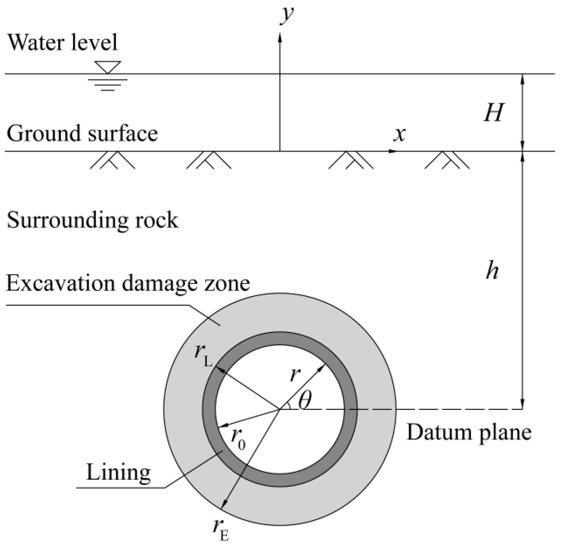
2. Analytical Solutions
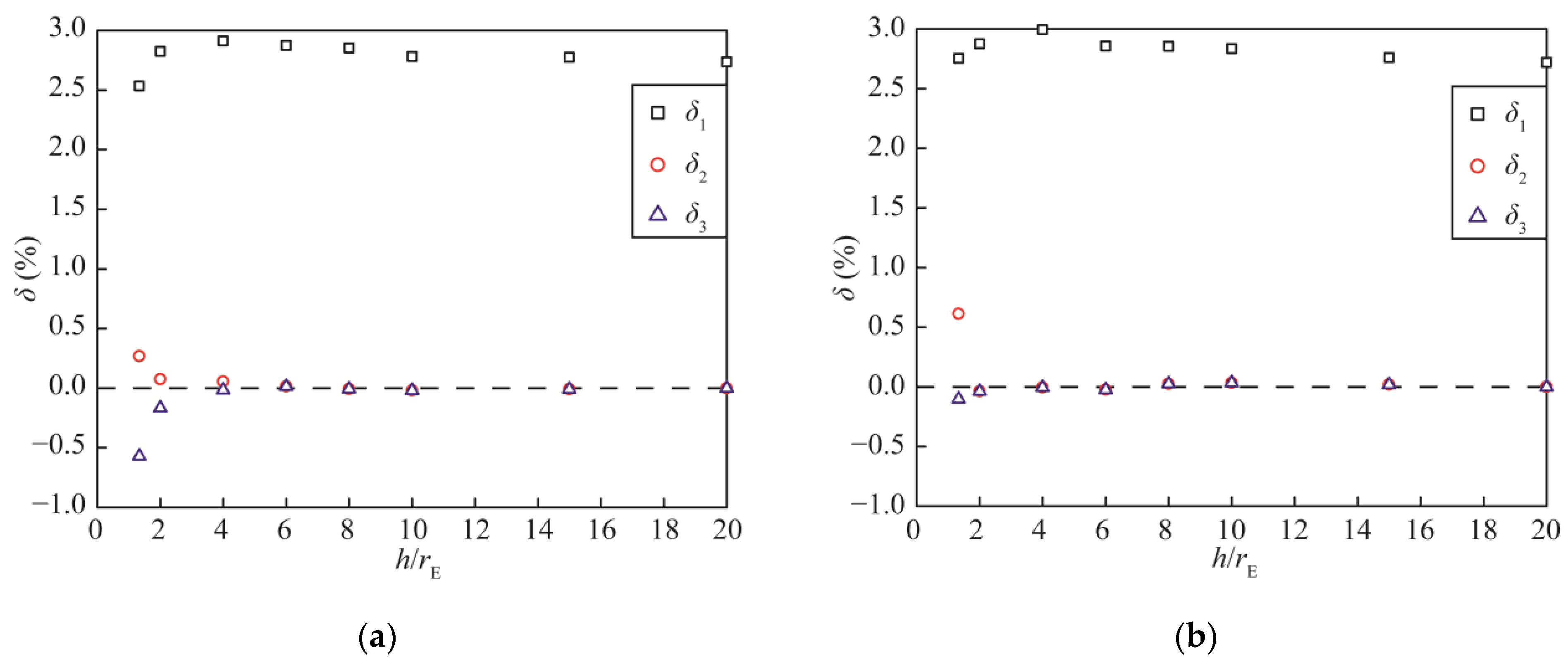
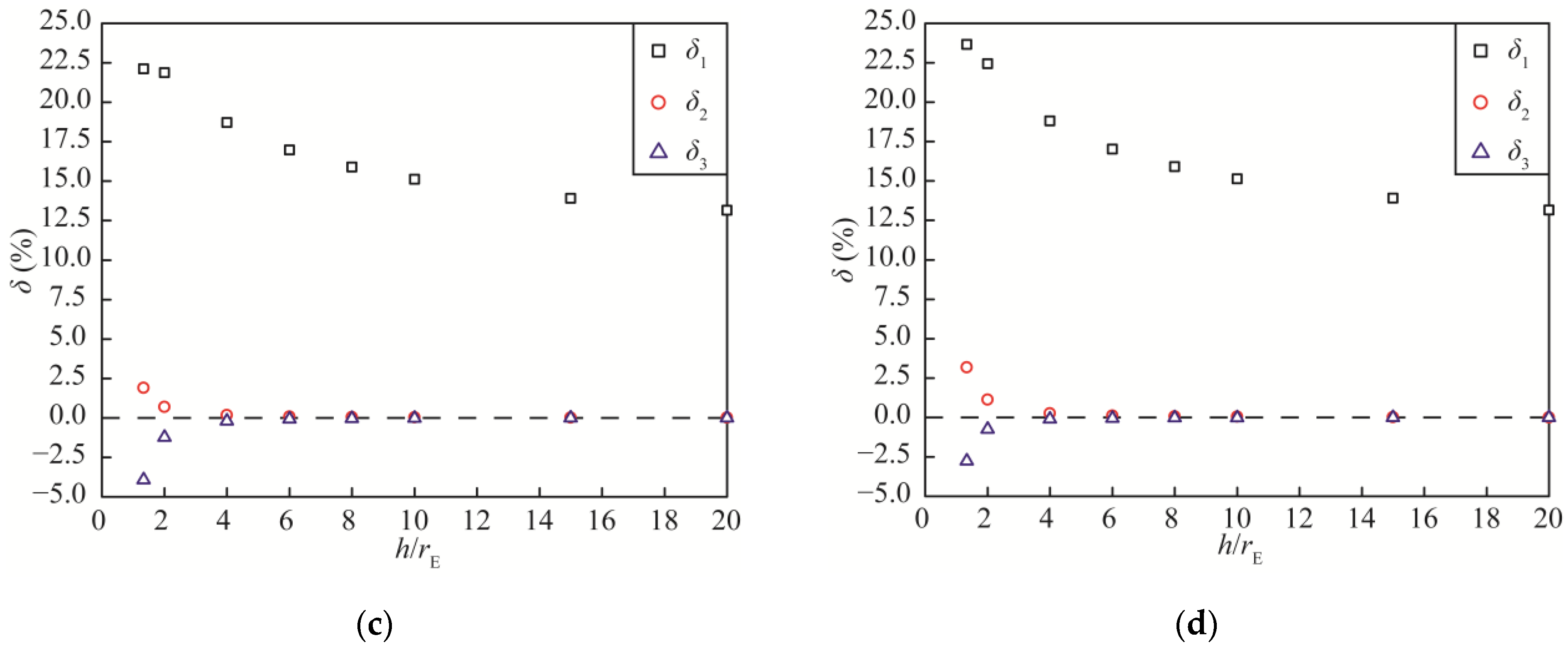
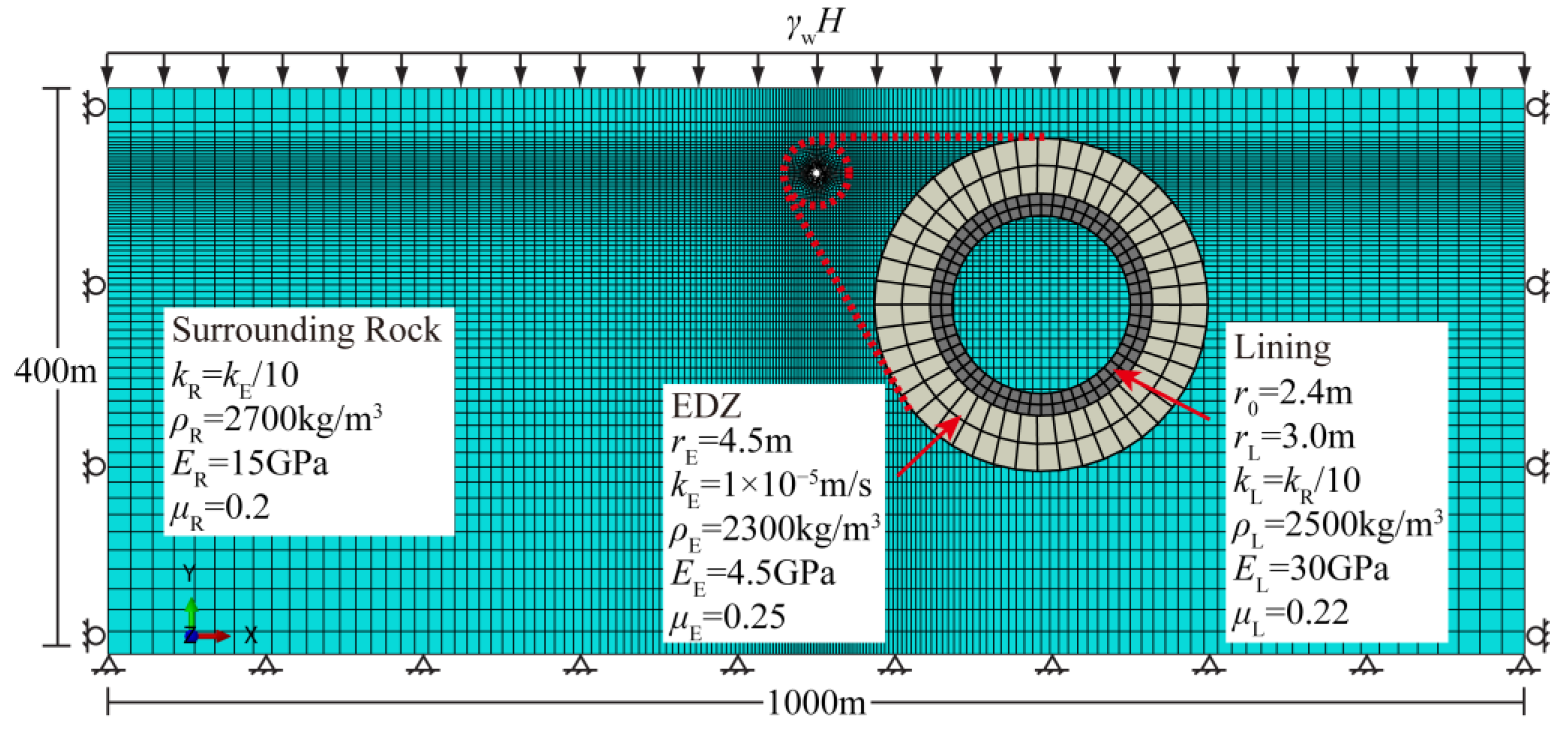
3. Numerical Method
4. Discussion
4.1. Effect of EDZ on Water Inflow
4.2. Effect Evaluation in Real Engineering Case
4.3. Seepage-Preventing Effect of Grouting
5. Conclusions
- The ratio decreases as the permeability and thickness of the EDZ increase, and the variation amplitude increases with the decrease in . Hence, the variations in EDZ parameters a and b have a greater impact on , as the tunnel is buried more shallowly.
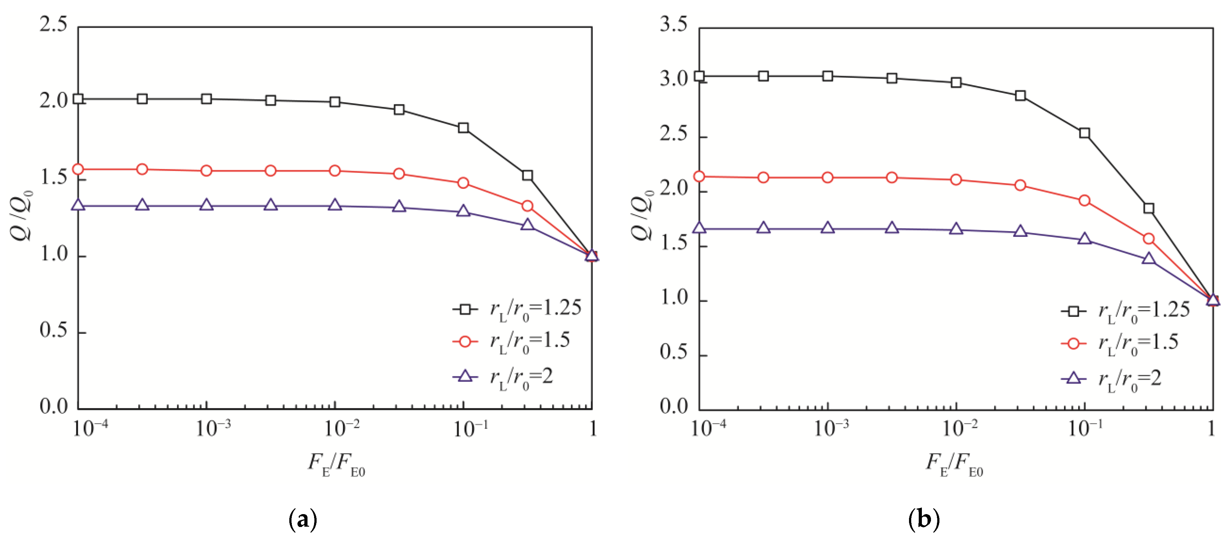
- The ratio increases as decreases, namely, as a and b increase. However, there is a limit for the influence of the EDZ on water inflow into the tunnel, and the increase in the impermeability and thickness of the lining can reduce the effect of the EDZ on water inflow.
- The difference in values between deep and shallow tunnels decreases with increasing impermeability and lining thickness. Furthermore, the effect of the EDZ is stronger for underwater tunnels with small water inflows and stabilizes as the magnitude of the water inflow increases.
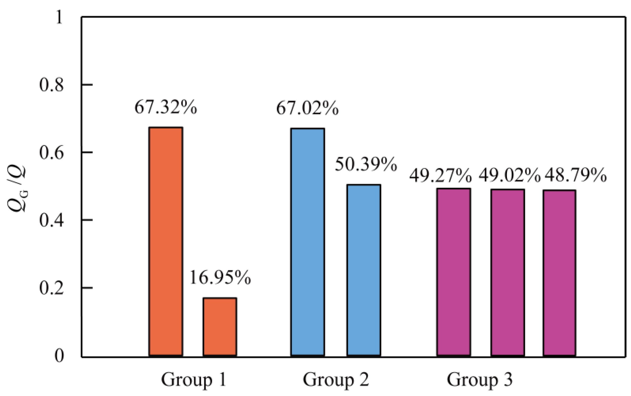
- Grouting is an effective measure to eliminate the effect of the EDZ on water inflow into tunnels. The increase in the impermeability and thickness of the grouting circle can reduce water inflow into the tunnel, and the initial values of and have little effect on . In addition, reducing the water inflow by improving the impermeability of the grouting circle on the premise of in practical engineering is preferred.
Author Contributions
Funding
Data Availability Statement
Conflicts of Interest
References
- Coli, M.; Pinzani, A. Tunnelling and hydrogeological issues: A short review of the current state of the art. Rock Mech. Rock Eng. 2014, 47, 839–851. [Google Scholar] [CrossRef]
- Nilsen, B. Characteristics of water ingress in Norwegian subsea tunnels. Rock Mech. Rock Eng. 2014, 47, 933–945. [Google Scholar] [CrossRef]
- Zhao, J.; Tan, Z.; Ma, N. Development and application of a new reduction coefficient of water pressure on sub-sea tunnel lining. Appl. Sci. 2022, 12, 2496. [Google Scholar] [CrossRef]
- Peng, Y.; Wu, L.; Zuo, Q.; Chen, C.; Hao, Y. Risk assessment of water inrush in tunnel through water-rich fault based on AHP-Cloud model. Geomat. Nat. Hazards Risk 2020, 11, 301–317. [Google Scholar] [CrossRef] [Green Version]
- Liu, R.; Liu, Y.; Xin, D.; Li, S.; Zheng, Z.; Ma, C.; Zhang, C. Prediction of water inflow in subsea tunnels under blasting vibration. Water 2018, 10, 1336. [Google Scholar] [CrossRef] [Green Version]
- Cao, Y.; Jiang, J.; Xie, K.; Huang, W. Analytical solutions for nonlinear consolidation of soft soil around a shield tunnel with idealized sealing linings. Comput. Geotech. 2014, 61, 144–152. [Google Scholar] [CrossRef]
- Shin, Y.; Song, K.; Lee, I.; Cho, G. Interaction between tunnel supports and ground convergence—Consideration of seepage forces. Int. J. Rock Mech. Min. 2011, 48, 394–405. [Google Scholar] [CrossRef]
- Yang, G.; Wang, X.; Wang, X.; Cao, Y. Analyses of seepage problems in a subsea tunnel considering effects of grouting and lining structure. Mar. Georesour. Geotec. 2016, 34, 65–70. [Google Scholar] [CrossRef]
- Zhang, D.M.; Huang, Z.K.; Yin, Z.Y.; Ran, L.Z.; Huang, H.W. Predicting the grouting effect on leakage-induced tunnels and ground response in saturated soils. Tunn. Undergr. Space Technol. 2017, 65, 76–90. [Google Scholar] [CrossRef]
- Farhadian, H.; Nikvar-Hassani, A. Water flow into tunnels in discontinuous rock: A short critical review of the analytical solution of the art. Bull. Eng. Geol. Environ. 2019, 78, 3833–3849. [Google Scholar] [CrossRef]
- Fernandez, G.; Moon, J. Excavation-induced hydraulic conductivity reduction around a tunnel—Part 1: Guideline for estimate of ground water inflow rate. Tunn. Undergr. Space Technol. 2010, 25, 560–566. [Google Scholar] [CrossRef]
- Bai, Y.; Wu, Z.; Huang, T.; Peng, D. A Dynamic modeling approach to predict water inflow during karst tunnel excavation. Water 2022, 14, 2380. [Google Scholar] [CrossRef]
- Li, P.; Wang, F.; Long, Y.; Zhao, X. Investigation of steady water inflow into a subsea grouted tunnel. Tunn. Undergr. Space Technol. 2018, 80, 92–102. [Google Scholar] [CrossRef]
- Moon, J.; Fernandez, G. Effect of excavation-induced groundwater level drawdown on tunnel inflow in a jointed rock mass. Eng. Geol. 2010, 110, 33–42. [Google Scholar] [CrossRef]
- Butscher, C. Steady-state groundwater inflow into a circular tunnel. Tunn. Undergr. Space Technol. 2012, 32, 158–167. [Google Scholar] [CrossRef]
- Farhadian, H.; Nikvar Hassani, A.; Katibeh, H. Groundwater inflow assessment to Karaj Water Conveyance tunnel, northern Iran. KSCE J. Civ. Eng. 2017, 21, 2429–2438. [Google Scholar] [CrossRef]
- Fernandez, G.; Moon, J. Excavation-induced hydraulic conductivity reduction around a tunnel—Part 2: Verification of proposed method using numerical modeling. Tunn. Undergr. Space Technol. 2010, 25, 567–574. [Google Scholar] [CrossRef]
- Nikvar Hassani, A.; Farhadian, H.; Katibeh, H. A comparative study on evaluation of steady-state groundwater inflow into a circular shallow tunnel. Tunn. Undergr. Space Technol. 2018, 73, 15–25. [Google Scholar] [CrossRef]
- Nikvar Hassani, A.; Katibeh, H.; Farhadian, H. Numerical analysis of steady-state groundwater inflow into Tabriz line 2 metro tunnel, northwestern Iran, with special consideration of model dimensions. Bull. Eng. Geol. Environ. 2016, 75, 1617–1627. [Google Scholar] [CrossRef]
- Farhadian, H.; Katibeh, H.; Huggenberger, P. Empirical model for estimating groundwater flow into tunnel in discontinuous rock masses. Environ. Earth Sci. 2016, 75, 417. [Google Scholar] [CrossRef]
- Gattinoni, P.; Scesi, L. An empirical equation for tunnel inflow assessment: Application to sedimentary rock masses. Hydrogeol. J. 2010, 18, 1797–1810. [Google Scholar] [CrossRef]
- Wang, X.; Tan, Z.; Wang, M.; Zhang, M.; Ming, H. Theoretical and experimental study of external water pressure on tunnel lining in controlled drainage under high water level. Tunn. Undergr. Space Technol. 2008, 23, 552–560. [Google Scholar] [CrossRef]
- Huangfu, M.; Wang, M.; Tan, Z.; Wang, X. Analytical solutions for steady seepage into an underwater circular tunnel. Tunn. Undergr. Space Technol. 2010, 25, 391–396. [Google Scholar] [CrossRef]
- Harr, M.E. Groundwater and Seepage; McGraw-Hill: New York, NY, USA, 1962. [Google Scholar]
- Goodman, R.E.; Moye, D.G.; Schalkwyk, A.; Javandel, I. Ground water inflow during tunnel driving. Eng. Geol. 1965, 2, 39–56. [Google Scholar]
- Lei, S. An analytical solution for steady flow into a tunnel. Ground Water 1999, 37, 23–26. [Google Scholar] [CrossRef]
- Ying, H.; Zhu, C.; Gong, X. Analytic solution on seepage field of underwater tunnel considering grouting circle. J. Zhejiang Univ. Eng. Sci. 2016, 50, 1018–1023. [Google Scholar]
- Su, K.; Zhou, Y.; Wu, H.; Shi, C.; Zhou, L. An analytical method for groundwater inflow into a drained circular tunnel. Ground Water 2017, 55, 712–721. [Google Scholar] [CrossRef]
- El Tani, M. Circular tunnel in a semi-infinite aquifer. Tunn. Undergr. Space Technol. 2003, 18, 49–55. [Google Scholar] [CrossRef]
- Kolymbas, D.; Wagner, P. Groundwater ingress to tunnels—The exact analytical solution. Tunn. Undergr. Space Technol. 2007, 22, 23–27. [Google Scholar] [CrossRef]
- Park, K.; Owatsiriwong, A.; Lee, J. Analytical solution for steady-state groundwater inflow into a drained circular tunnel in a semi-infinite aquifer: A revisit. Tunn. Undergr. Space Technol. 2008, 23, 206–209. [Google Scholar] [CrossRef]
- Ying, H.; Zhu, C.; Shen, H.; Gong, X. Semi-analytical solution for groundwater ingress into lined tunnel. Tunn. Undergr. Space Technol. 2018, 76, 43–47. [Google Scholar] [CrossRef]
- Du, C.; Wang, M.; Tan, Z. Analytical solution for seepage field of subsea tunnel and its application. Chin. J. Rock Mech. Eng. 2011, 30, 3567–3573. [Google Scholar]
- Li, P.; Zhang, D.; Zhao, Y.; Zhang, C. Study of distribution law of water pressure acting on composite lining and reasonable parameters of grouting circle for subsea tunnel. Chin. J. Rock Mech. Eng. 2012, 31, 280–288. [Google Scholar]
- Pan, Y.; Luo, Q.; Zhou, B.; Chen, J. Analytical study on seepage field of deep tunnel with grouting circle in half plane. J. Zhejiang Univ. Eng. Sci. 2018, 52, 1114–1122. [Google Scholar]
- Zhu, C.; Ying, H.; Gong, X. Analytical solutions for seepage fields of underwater tunnels with arbitrary burial depth. Chin. J. Geotech. Eng. 2017, 39, 1984–1991. [Google Scholar]
- Butscher, C.; Einstein, H.H.; Huggenberger, P. Effects of tunneling on groundwater flow and swelling of clay-sulfate rocks. Water Resour. Res. 2011, 47, 1–17. [Google Scholar] [CrossRef]
- Peng, Y.; Liu, G.; Wu, L.; Zuo, Q.; Liu, Y.; Zhang, C. Comparative study on tunnel blast-induced vibration for the underground cavern group. Environ. Earth Sci. 2021, 80, 68. [Google Scholar] [CrossRef]
- Martino, J.B.; Chandler, N.A. Excavation-induced damage studies at the Underground Research Laboratory. Int. J. Rock Mech. Min. 2004, 41, 1413–1426. [Google Scholar] [CrossRef]
- Tsang, C.; Bernier, F.; Davies, C. Geohydromechanical processes in the Excavation Damaged Zone in crystalline rock, rock salt, and indurated and plastic clays—In the context of radioactive waste disposal. Int. J. Rock Mech. Min. 2005, 42, 109–125. [Google Scholar] [CrossRef]
- Souley, M.; Homand, F.; Pepa, S.; Hoxha, D. Damage-induced permeability changes in granite: A case example at the URL in Canada. Int. J. Rock Mech. Min. 2001, 38, 297–310. [Google Scholar] [CrossRef]
- Bossart, P.; Meier, P.M.; Moeri, A.; Trick, T.; Mayor, J. Geological and hydraulic characterisation of the excavation disturbed zone in the Opalinus Clay of the Mont Terri Rock Laboratory. Eng. Geol. 2002, 66, 19–38. [Google Scholar] [CrossRef]
- Schleiss, A. Design of reinforced concrete linings of pressure tunnels and shafts. Int. J. Hydropower Dams 1997, 4, 88–94. [Google Scholar]


| Reference | Equation | Description |
|---|---|---|
| Yang et al. [8] | Homogeneous and isotropic media For both shallow and deep drained tunnels | |
| Du et al. [33]; Pan et al. [35] | Homogeneous and isotropic media Deep tunnels | |
| Ying et al. [27] | Homogeneous and isotropic media Deep drained tunnels | |
| Zhu et al. [36] | Homogeneous and isotropic media For both shallow and deep drained tunnels |
| Surrounding Rock | EDZ | Lining | |||
|---|---|---|---|---|---|
| H | 0 m, 45 m | rE | 4.5 m | rL | 3 m |
| h | 6~90 m | kE | 1 × 10⁻⁵ m/s | r0 | 2.4 m |
| kR | 1 × 10⁻⁶ m/s | - | - | kL | 1 × 10⁻⁷ m/s, 1 × 10⁻⁸ m/s |
| 10 | 10 | 1.33 | 8.875 | 8.861 | 8.858 | 4.633 | 4.630 |
| 2 | 8.156 | 8.149 | 8.112 | 4.252 | 4.233 | ||
| 4 | 7.916 | 7.913 | 7.876 | 4.106 | 4.087 | ||
| 6 | 8.223 | 8.222 | 8.223 | 4.231 | 4.248 | ||
| 8 | 8.723 | 8.721 | 8.720 | 4.478 | 4.488 | ||
| 10 | 9.294 | 9.293 | 9.277 | 4.770 | 4.762 | ||
| 15 | 10.723 | 10.722 | 10.766 | 5.504 | 5.497 | ||
| 20 | 12.218 | 12.217 | 12.295 | 6.217 | 6.257 | ||
| 0 | 1.33 | 1.029 | 1.031 | 1.029 | 0.717 | 0.716 | |
| 2 | 1.377 | 1.352 | 1.346 | 0.854 | 0.850 | ||
| 4 | 2.260 | 2.259 | 2.248 | 1.279 | 1.273 | ||
| 6 | 3.089 | 3.061 | 3.082 | 1.651 | 1.677 | ||
| 8 | 3.879 | 3.862 | 3.875 | 2.048 | 2.066 | ||
| 10 | 4.641 | 4.646 | 4.638 | 2.446 | 2.442 | ||
| 15 | 6.431 | 6.431 | 6.459 | 3.327 | 3.344 | ||
| 20 | 8.198 | 8.145 | 8.197 | 4.181 | 4.207 |
| Scheme No. | a | b | |||||
|---|---|---|---|---|---|---|---|
| 1 | 5 | 1000 | 5 | 0.07% | 1 | 1.25 | 11.19 |
| 50 | 1000 | 5 | 65.03% | 1 | 1.25 | 1.50 | |
| 2 | 5 | 1000 | 5 | 0.07% | 10 | 1.25 | 2.03 |
| 50 | 1000 | 5 | 65.03% | 10 | 1.25 | 1.31 | |
| 3 | 5 | 1000 | 5 | 0.07% | 1 | 2 | 4.30 |
| 50 | 1000 | 5 | 65.03% | 1 | 2 | 1.44 |
| (m) | (m) | (m/s) | ||
|---|---|---|---|---|
| 8 | 9 | 1 × 10⁻⁷ | 10 | 1.5 |
| No. | Mileage | (m/s) | (m) | (m) | ||
|---|---|---|---|---|---|---|
| 1 | ZK3 + 125–ZK3 + 325 | 1.74 × 10⁻⁷ | 27 | 0 | 1.629 | 1.259 |
| 2 | ZK3 + 325–ZK3 + 595 | 8.1 × 10⁻⁷ | 30.3 | 5 | 6.356 | 1.162 |
| 3 | ZK3 + 595–ZK3 + 932 | 4.63 × 10⁻⁷ | 40.6 | 5.3 | 4.906 | 1.162 |
| 4 | ZK3 + 932–ZK4 + 102 | 3.47 × 10⁻⁷ | 46.4 | 6.6 | 4.241 | 1.160 |
| 5 | ZK4 + 102–ZK4 + 362 | 4.63 × 10⁻⁷ | 44.9 | 12.4 | 5.860 | 1.154 |
| 6 | ZK4 + 362–ZK4 + 422 | 1.5 × 10⁻⁶ | 44.9 | 16.1 | 13.520 | 1.103 |
| 7 | ZK4 + 422–ZK4 + 562 | 4.05 × 10⁻⁷ | 43.7 | 19.8 | 5.915 | 1.161 |
| 8 | ZK4 + 562–ZK4 + 627 | 6.94 × 10⁻⁷ | 43.64 | 21.86 | 9.145 | 1.140 |
| 9 | ZK4 + 627–ZK4 + 917 | 3.47 × 10⁻⁷ | 43.24 | 26.26 | 5.742 | 1.166 |
| 10 | ZK4 + 917–ZK4 + 977 | 4.63 × 10⁻⁷ | 43.5 | 29.3 | 7.548 | 1.156 |
| 11 | ZK4 + 977–ZK5 + 022 | 4.63 × 10⁻⁷ | 43.86 | 30.64 | 7.697 | 1.156 |
| 12 | ZK5 + 022–ZK5 + 212 | 9.26 × 10⁻⁷ | 44.37 | 33.43 | 13.08 | 1.127 |
| 13 | ZK5 + 212–ZK5 + 372 | 3.47 × 10⁻⁷ | 43 | 37.2 | 6.643 | 1.167 |
| 14 | ZK5 + 372–ZK5 + 482 | 1.16 × 10⁻⁷ | 41.7 | 40.8 | 2.631 | 1.193 |
| 15 | ZK5 + 482–ZK6 + 082 | 1.16 × 10⁻⁷ | 40.5 | 42.4 | 2.685 | 1.197 |
| Scheme No. | ||||||||
|---|---|---|---|---|---|---|---|---|
| 1 | 0.1 | 2 | 10 | 2 | 10 | 1.25 | 2.5 | 2.5 |
| 0.1 | 2 | 100 | 2 | 10 | 1.25 | 2.5 | 2.5 | |
| 2 | 0.01 | 2 | 10 | 2 | 10 | 1.25 | 2.5 | 2.5 |
| 0.01 | 2 | 10 | 4 | 10 | 1.25 | 2.5 | 2.5 | |
| 3 | 0.1 | 4 | 10 | 4 | 10 | 1.25 | 1.25 | 1.25 |
| 0.1 | 2 | 10 | 4 | 10 | 1.25 | 1.25 | 1.25 | |
| 0.01 | 2 | 10 | 4 | 10 | 1.25 | 1.25 | 1.25 |
Publisher’s Note: MDPI stays neutral with regard to jurisdictional claims in published maps and institutional affiliations. |
© 2022 by the authors. Licensee MDPI, Basel, Switzerland. This article is an open access article distributed under the terms and conditions of the Creative Commons Attribution (CC BY) license (https://creativecommons.org/licenses/by/4.0/).
Share and Cite
Pan, Y.-H.; Qi, J.-R.; Zhang, J.-F.; Peng, Y.-X.; Chen, C.; Ma, H.-N.; Ye, C. A Comparative Study on Steady-State Water Inflow into a Circular Underwater Tunnel with an Excavation Damage Zone. Water 2022, 14, 3154. https://doi.org/10.3390/w14193154
Pan Y-H, Qi J-R, Zhang J-F, Peng Y-X, Chen C, Ma H-N, Ye C. A Comparative Study on Steady-State Water Inflow into a Circular Underwater Tunnel with an Excavation Damage Zone. Water. 2022; 14(19):3154. https://doi.org/10.3390/w14193154
Chicago/Turabian StylePan, Yi-Heng, Jia-Rui Qi, Jin-Feng Zhang, Ya-Xiong Peng, Chao Chen, Hai-Nan Ma, and Chen Ye. 2022. "A Comparative Study on Steady-State Water Inflow into a Circular Underwater Tunnel with an Excavation Damage Zone" Water 14, no. 19: 3154. https://doi.org/10.3390/w14193154