
Optimized Removal of Azo Dyes from Simulated Wastewater through Advanced Plasma Technique with Novel Reactor
by
 , ,
, ,
Yang Liu
1,* ,
,
Jia-Wei Song
1,
Jia Bao
1,*,
Xin-Jun Shen
1,
Cheng-Long Li
1,
Xin Wang
1 and
Li-Xin Shao
2 1
School of Environmental and Chemical Engineering, Shenyang University of Technology, Shenyang 110870, China
2
School of Mechanical Engineering, Shenyang University of Technology, Shenyang 110870, China
*
Authors to whom correspondence should be addressed.
Water 2022, 14(19), 3152; https://doi.org/10.3390/w14193152
Submission received: 14 September 2022
/
Revised: 26 September 2022
/
Accepted: 4 October 2022
/
Published: 6 October 2022
(This article belongs to the Special Issue Advanced Oxidation Processes for Emerging Contaminant Removal)
Abstract
:Increasing attention has been paid to removal of aqueous contaminations resulting from azo dyes in water by plasma technology. However, the influence factors and removal mechanism of plasma technology were still obscure, moreover, energy consumption and oxidized degradation efficiency of plasma reactor were also inferior. In the present study, a comparative analysis was performed using 100 mg/L of Methyl Orange (MO) in the simulated wastewater with a novel plasma reactor to achieve the ideal parameters involving voltage, discharge gap, and discharge needle numbers. Therefore, the optimal removal rate for MO could be up to 95.1% and the energy consumption was only 0.26 kWh/g after the plasma treatment for 60 min, when the voltage was set as 15 kV, the discharge gap was 20 mm, and the discharge needle numbers was 5. Based upon the response surface methodology (RSM), the removal rate of MO was predicted as 99.3% by massive optimization values in software, and the optimum conditions were confirmed with the plasma treatment period of 60 min, the voltage of 14.8 kV, the discharge gap of 20 mm, and the discharge needles of 5. Plasma associated with catalysts systems including plasma, plasma/Fe2+, plasma/PS, and plasma/PS/Fe2+ were further investigated, and the best removal rate for MO reached 99.2% at 60 min under the plasma/PS/Fe2+ system due to simultaneously synergistic reactions of HO• and SO4•−. Moreover, it was also revealed that –N=N– bond was attacked and broken by active species like HO•, and the oxidized by-products of benzenesulfonic acid and phenolsulfonic acid might be generated, via the analysis of the variation in the absorbances through UV-Vis spectrophotometry during the plasma treatment. As a result, the advanced plasma technique in this study presented excellent efficacy for MO removal from simulated wastewater with low energy consumption.
1. Introduction
In 1862, the inartificial dyes were initially obtained from natural sources, including leaves, roots, and branches, etc. [1], which usually limited the range of colors [2]. Thereafter, various kinds of artificial dyes were explored to satisfy daily demands. According to their chemical structures and chromophores, dyes are classified as azo (mono-azo, di-azo, tri-azo, poly-azo), anthraquinone, phthalocyanine, diarylmethane, triarylmethane, indigo, azine, oxazine, thiazine, xanthene, nitro, nitroso, methine, thiazole, indamine, indophenol, lactone, amino ketone, hydroxyl ketone stibene, and sulfur dyes [3]. So far, there are over two thousand types of dyes available for commercial purposes in the market with quantities exceeding 7 × 10⁵ tons worldwide annually [4,5], of which over 50% were azo dyes [4]. Azo dyes are a class of organic compounds with azo linkages (–N=N–) connecting aryl groups, which were widely used in textile, printing, paper and other fields [1,4].
Azo dyes possessed strong physical and chemical stability, extraordinary resistance to high temperature, photolysis, biological and oxidative degradation [6]. Therefore, great quantities utilizing and inappropriate discharge of azo dyes have resulted in water pollutions and accumulations in the water cycle, threatening the safety of drinking water. Textile-processing units discharged extremely colored water effluents with dye content in the range of 10–200 mg/L [3]. For instance, the outflow concentration of the dye Acid Orange 10 from the final clarifier of a textile factory in India was 45 mg/L [7]. The outflow concentrations of azo dye from 14 Ramadan textile industries in Iraq ranged between 20 mg/L and 50 mg/L [7]. Human exposure to these azo dyes and their intermediates would cause mutagenic, carcinogenic, nervous system disorders, and dermatitis [8], as well as severe and long-lasting impact on the liver, kidney, brain, and reproduction system [9]. Therefore, increasing efforts would be warranted to implement the elimination of azo dyes from waters.
Azo dyes usually contain a strong stable benzene ring structure and azo bonds that prevent mineralization, and even dissolved functional groups of sulfonate, hydroxyl, or carboxyl, leading to difficult water treatment [10,11,12,13]. Extensive research has been done on utilizing physical and chemical techniques for the removal of azo dyes, including adsorption, chemical oxidation, biological techniques, and plasma technology [14,15,16], etc. The adsorption method could adsorb azo dyes effectively, but only by transferring the contaminants from water to the solid phase, without achieving the degradation effect [17], and the adsorbent regeneration was an intractable problem [18]. The chemical oxidation process could decolorize azo dyes, but the mineralization rates were usually inferior, and the addition of chemical agents was inclined to cause secondary pollution [16,19]. The biological method was used for azo dyes degradation due to their high activity and strong adaptability [20], but high levels of azo dyes could inhibit the activity of bacteria [16]. Therefore, an environmentally friendly and high efficiency degradation technique for azo dyes was required for developing to overcome the above-mentioned problems.
Plasma technology is considered as the advanced oxidation process (AOP); the plasma discharge could break molecular structure efficiently by its generation of strong active species (HO•, H•O•, HO2•, NO2•, etc.) and other physiochemical effects (UV irradiation, shockwaves, local high temperature, etc.) in situ [17,21,22]. The water molecule of solution in the discharge process leads to produce HO• and H• by its dissociation, ionization, and vibrational/rotational excitation, as shown in Equations (1)–(4) [15]. H• and O• could be generated by vibrationally/rotationally excited water molecules that are released into a lower energetic state, as shown in Equations (5)–(7) [15]. Subsequently, the enduring H2O2 could be formed by dimerization of HO• (Equation (8)) [23]. In addition, plasma containing water has UV light emission as a result of exited species relaxation to lower energetic states, which are generated from the collisions between electrons and neutral molecules [15]. In the plasma treatment process, the organic molecules (M) absorb the radiation and transfer into an excited state (M*) by ultraviolet radiation, whereafter the excited M* could be decomposed into a new product in the transversion of M* goes back to the ground state immediately due to short lifetime (10−9–10−8 s), as shown in the Equation (9) [15]. Thus, this technique was suitable for the removal of degradation-resistant organic compounds [16]. Ma et al. have used Dielectric Barrier Discharge (DBD) plasma technology to degrade 44.36 g/L of methylene blue (MB), the degradation rate could reach up to 98.3% after 3 min [24]. Sarangapani et al., have used Box-Benkhen Design (BBD) model and Response Surface Methodology (RSM) to optimize the experimental parameters of the DBD plasma technique for Methyl Orange (MO) degradation, which determined the optimal experimental conditions with voltage at 70 kV, treatment time as 120 s, and MO concentration as 100 mg/L [25].
However, the influence factors and degradation mechanism of plasma technology on azo dyes at the molecular level were still obscure, as well as usually followed with high energy consumption and inferior degradation efficiency due to low mass transfer efficiency between gas and liquid phase in plasma reactor [26,27]. In general, active species including HO•, H•, O•, etc. generated from plasma could penetrate into liquid, but with shallow penetration depth and attain some dozens of microns [28].
Therefore, the establishment of the interaction between active species and organic contaminants would enhance the removal efficacy. In this study, a novel reactor with an improved plasma area was designed through regulating the grounded plate and the plasma discharge area, which could increase the removal efficiency by the intensive reaction between active species and MO contaminants on the interface of gas-liquid. Moreover, the addition of typical catalysts such as persulfate (PS) and Fe2+ would present excellent degradation efficacy due to the high oxidizability of generated active species [29,30,31,32].
In order to solve the above-said problems, the plasma technique for the azo dyes was implemented in the present study to achieve the objectives as follows: (1) confirm the optimal influence parameters by comparing the plasma removal performance on the target azo dye of MO under different conditions, involving the reaction time, voltage, discharge gap, and discharge needle numbers; (2) improve MO removal efficiency and reduce energy consumption using the novel plasma reactor through the optimal response surface methodology (RSM); (3) investigate the removal efficiency of plasma associated with catalyst system including PS/Fe2+; and (4) determine the removal mechanism via the UV-Vis analysis of MO during the plasma process.
2. Materials and Methods
2.1. Chemicals and Reagents
Methyl Orange (MO, 99.9%) was acquired from Fluka (Steinheim, Germany). Sodium hydroxide (NaOH, 99.9%), ferrous sulfate (FeSO4, 99.9%), and sodium persulphate (Na2S2O8, 99.9%) were purchased from Acros Organics (Geel, Belgium). All solutions were prepared using ultrapure water with a conductance of 18.2 MΩ/cm (Millipore, Bedford, MA, USA).
2.2. Experimental Setup and Procedure
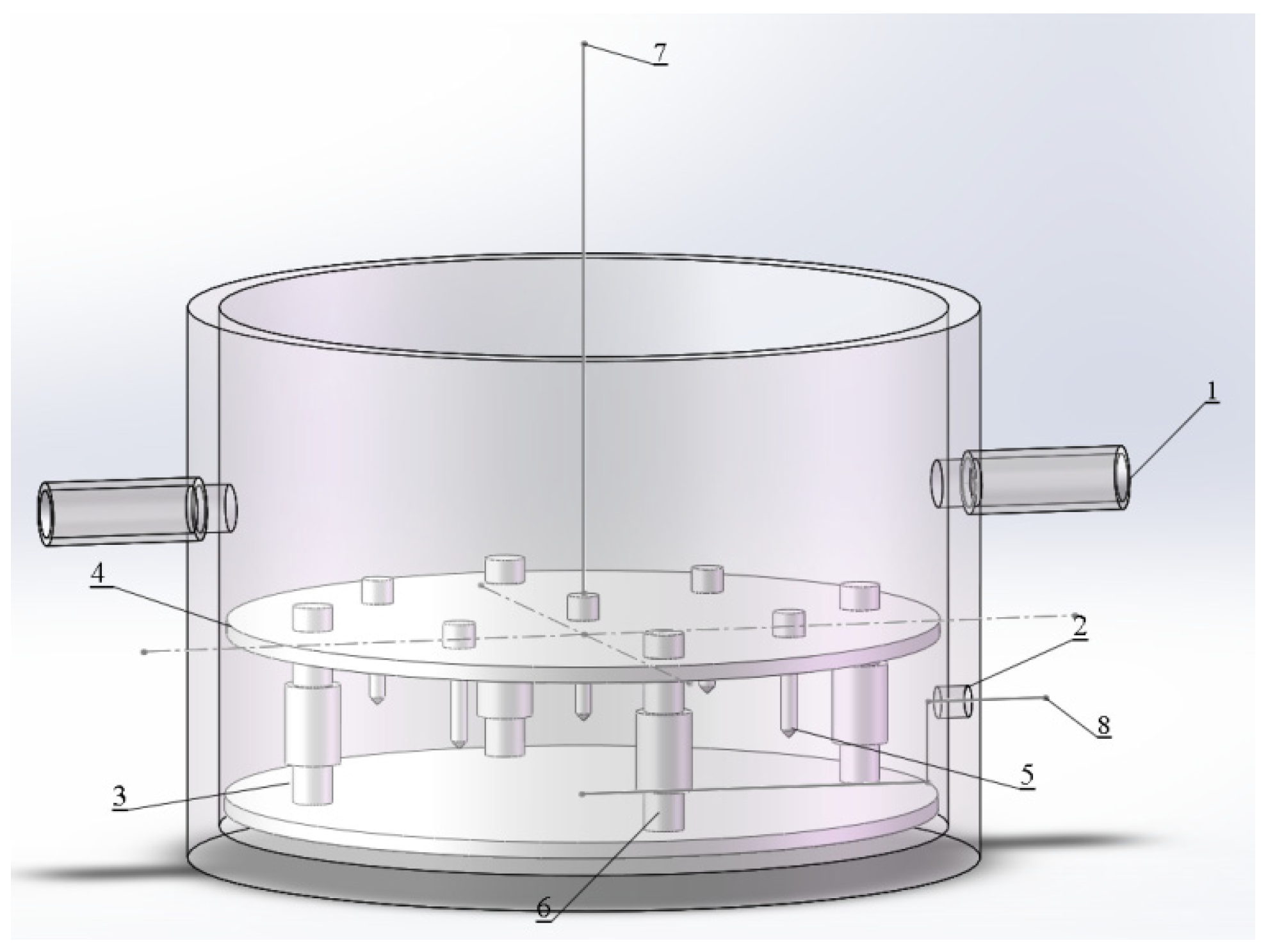
A novel reactor was designed as a cylinder with well appropriate between the plasma discharge area and the grounded electrode in the bottom of the reactor. The novel reactor could increase the effective discharge area for active species formation during the plasma process. The fully propagated plasma occupied a roughly circular region on the liquid surface with visually uniform leader distribution [33]. As shown in Figure 1, the novel plasma reactor was an organic glass reactor with a 50 mL effective volume for MO removal from simulated wastewater. In detail, the bottom radius was 50 mm, the height was 70 mm, and the wall thickness was 5 mm. Two air vents with a radius of 4 mm were set on both sides, which were 20 mm away from the top of the reactor. A sample collection hole with a 4 mm diameter was installed at 12 mm away from the bottom of reactor. The mass transfer efficiency of active species in liquid could be improved by enhancing the air tightness of the reactor, all vents were blocked with an airtight polymer cap during the operation. The circular grounded metal electrode plate with a 45 mm radius and 2 mm thickness was immersed in the MO solution, the same size as a perforated metal plate fixed with needle-like electrodes was used as high voltage discharge electrode plate. Needle-like electrodes were stainless steels which widely used due to their mechanical and anti-corrosion properties [34]. The nylon columns were used to support the high voltage electrode and the grounded electrode, and the high voltage electrode could be adjusted by the distance above the solution.
The high voltage direct current (DC) power supply (LYZGF, Zhi-Cheng Company, China) was used to generate plasma, characterized with the range of 0–60 kV for discharge voltage and 0–5 mA for output current. Based upon the important influence parameters, the discharge voltages were in the range between 11 kV and 15 kV, the discharge gap was between 19 mm and 21 mm, and discharge needle numbers were 3, 4, and 5, together with the initial MO concentration of 100 mg/L in simulated solution [35,36,37]. The added catalysts of Fe2+ and PS were set as 0.02 mmol/L under the optimal experimental conditions after the experimental factors were optimized by the RSM in the experiment of MO removal with plasma.
2.3. Sample Preparation and Analysis
The experimental duration of each plasma process was 60 min. Samples were taken at 0 min, 10 min, 20 min, 30 min, and 60 min, the reactor effluent from MO wastewater treatment was analyzed after filtration of glass fiber membrane (0.45 µm). The samples were scanned using an ultraviolet and visible (UV-Vis) spectrophotometer (DR 5000, Hach Company, Loveland, CO, USA) [38]. The absorbance was compared with the standard curve (Y = 0.7563x − 0.00831 R2 = 0.998) established at the maximum absorption wavelength of MO 462 nm [39], subsequently the concentration and removal rate of MO was calculated separately. The TOC values of collected samples were determined by the TOC analyzer (multi NC 3100, Analytik Jena AG Company, Jena, Germany) via direct nonpurgeable organic carbon (NPOC) measurement method to confirm the reduction of organic substances in solutions [24].
2.4. Data Analysis
- Removal rate of MO (η) %where η was the removal rate of MO in the solution, C0 and Ct were the concentration of MO solution at times of 0 and t, respectively.
- Energy consumption (W) kWh/gwhere W was the energy consumption of removing organic matter per unit weight, I was the output current, U was the output voltage, t was the discharge time, Δm was the removal weight of organic matter.
- Mineralization rate (XTOC) %where XTOC was the mineralization rate of MO, TOC0 and TOCt were total organic carbon at 0 min and t min, respectively.
2.5. RSM Experimental Design
Design-experimental V8.0.6.1 statistical software (Stat-Ease, Minneapolis, MN, USA) was applied to carry out the experimental design, analysis of variance (ANOVA), mathematical modeling, and 3D response surface [13]. Plackett-Burman, Central-Composite, and Box-Behnkhen Design (BDD) were widely used methods for RSM experiments, in which BDD followed the least number of quadratic model fitting experiments at three levels. As shown in Table 1, four significant operating parameters of a novel plasma reactor involving time (min), voltage (kV), discharge gap (mm), and discharge needle numbers were optimized using BBD in this study, and the removal rate of MO was the factor of response surface analysis [40]. In this study, four parameters presented three variation levels equally, which were codified as −1, 0, and 1 [13].
3. Results and Discussion
3.1. The Influence of Voltage
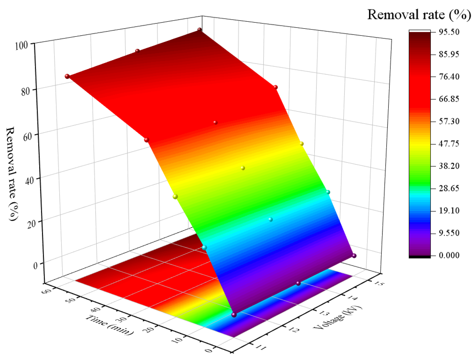
Discharge plasma originated by high voltage on the gas-liquid surface would generate various active species in the solution [35]. Thus, the discharge voltage was a significant factor on the removal of azo dye during the plasma treatment. To evaluate the effect of discharge voltage on MO removal, systematic experiments were implemented on plasma treatment with different applied voltages of 11 kV, 13 kV, and 15 kV. The other experiment parameters of the discharge needle numbers were set as 5, and the discharge gap was 20 mm. As shown from the contour plot of the response surface in Figure 2, the colors changed gradually from purple to red, which demonstrated that the removal rates of MO were enhanced over time. In addition, there was an increase at the same altitude, the removal rates of MO were improved with the voltage increasing in a certain applied voltage range. The interaction of voltage and treatment time showed a positive effect for the removal rate of MO. The removal rates of MO were 85.0%, 90.3%, and 95.1% at 60 min when each applied voltage were 11 kV, 13 kV, and 15 kV, respectively. This phenomenon was consistent with supplementary free radicals generated by high applied voltage [41]. Because additional energy electrons could be produced with the application of increasing voltages, which could intensify the collision chance between energetic electrons and air molecules effectively, thereafter producing extra excited oxygen atoms that could react with water molecules to generate extra HO• [35,42]. On the other hand, the plasma treatment process could generate ultraviolet radiation that improved the removal rate of MO, and the intensity of ultraviolet radiation could be enhanced at relatively high applied voltage [35]. However, high applied voltage would cost additional energy consumption and reduce energy utilization [43]. Therefore, the applied voltage was selected as 15 kV.
3.2. The Influence of Discharge Gap
Suitable discharge gap is important for MO removal in plasma, which influences the electric filed in the gap [36]. In this study, systematic experiments were conducted in plasma treatment with various discharge gaps of 19 mm, 20 mm, and 21 mm. The other parameters of the experiment including the applied voltage of 15 kV, and the number of discharge needles of 5. As shown from the contour plot of the response surface in Figure 3, the optimum removal rates of MO could achieve 89.1%, 96.7%, and 79.2% when the discharge gap was 19 mm, 20 mm, and 21 mm, respectively. The MO removal rates improved firstly when the discharge gap between 19 mm and 20 mm, but decreased subsequently when the discharge gap increased to 21 mm. It was because that corona discharge would change into unstable and noisy spark discharge when the discharge gap was low excessively, the generated spark discharge was not conductive to the active species due to the gap breakdown [44], whereas the removal rate of MO decreased to 79.2% when the discharge gap amplified to 21 mm. The discharge gap was related to electric filed intensity which could influence the movement speed of gas molecules in the discharge area [45], thereafter, the increased discharge gap would weaken the electric field intensity which declined the movement speed of gas molecules in the air under the same input energy and then generate scarcer active species [44,45]. Therefore, 20 mm was chosen as the optimal discharge gap for the plasma treatment.
3.3. The Influence of Discharge Needle Numbers
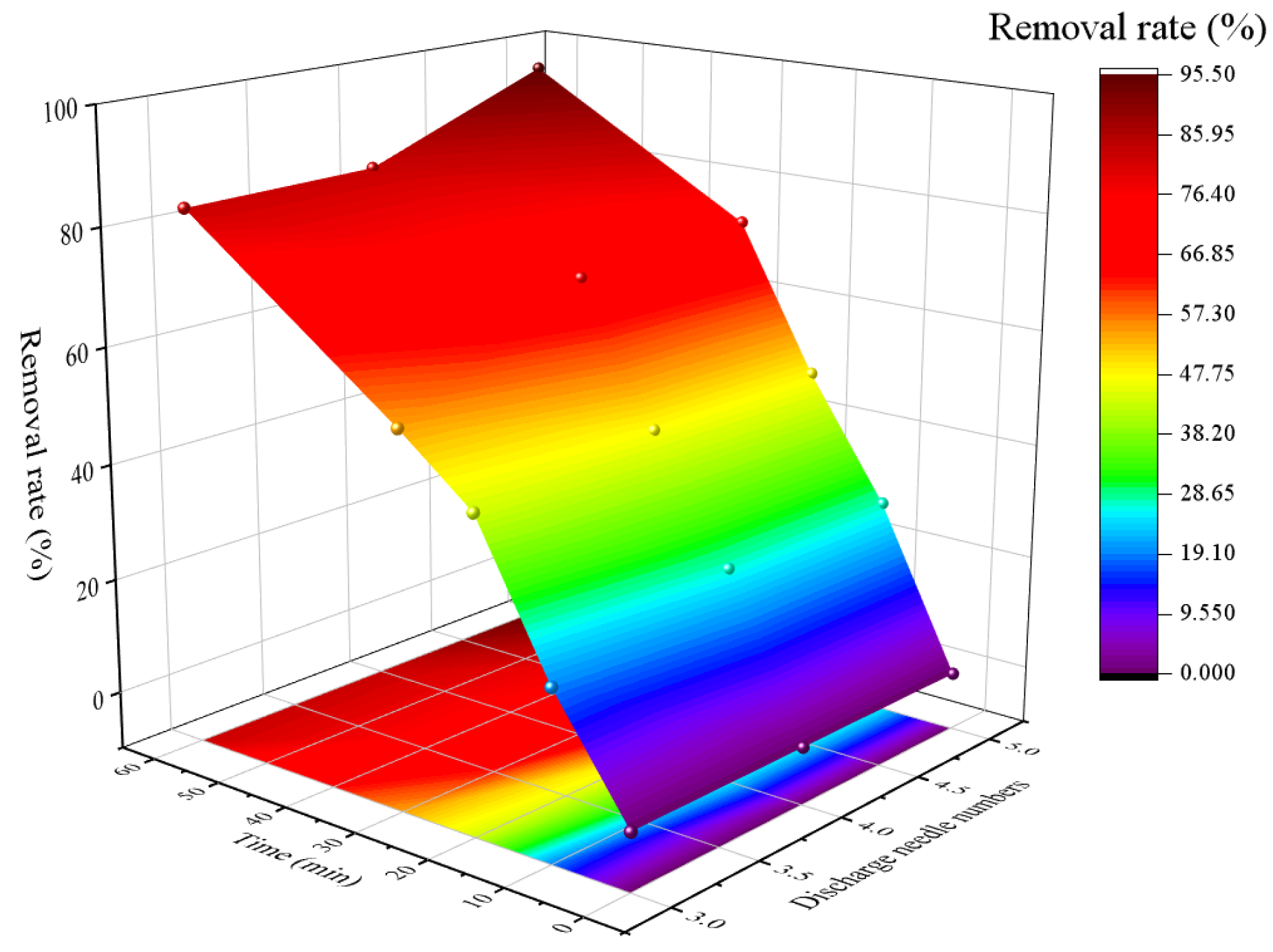
The numbers of discharge needle electrodes are related to the plasma channels between the discharge needle and liquid surface [37]; thus, it is important to get a suitable discharge needle numbers to enhance the removal rate of MO. To estimate the influence of discharge needle numbers on MO removal, different discharge needle numbers of 3, 4, and 5 were conducted in this plasma treatment. The other parameters were related to the applied voltage of 15 kV, and the discharge gap of 20 mm. As shown in the contour plot of the response surface in Figure 4, the removal rates of MO were improved with the growth of the treatment period and discharge needles number, subsequently the removal rate of MO was up to 95.1% at 60 min when the discharge needles number was 5. The results verified that the increase in discharge needle numbers expanded the discharge region to promote the chemical reactions between active species and MO [46]. However, the removal rates of MO were decreased to 82.5% and 82.8% individually at 60 min when the discharge needle numbers were 3 and 4, respectively. In general, needle-like electrodes generated fully propagated plasma channels at the liquid surface, and all types of active species were produced near plasma channels, thereafter the removal of MO mainly occurred in this circular area [33,47]. With the decline of discharge needle numbers, the plasma channels decreased, so the removal rates of MO were inferior due to depressed reaction region of active species with MO [37]. Therefore, 5 were chosen as the optimal discharge needles numbers in this study.
3.4. Analysis of RSM
RSM refers to a mathematical and statistical approach used to evaluate various aspects, including designing experiments, developing models, examining many independent variables, and assessing the optimum conditions for responses [48]. In the present study, four significant influencing parameters were selected and optimized at three levels through the ANOVA and mathematical modeling, for which, the removal rates of MO in the plasma treatment were applied as the response value. The test results were listed in Table 2.
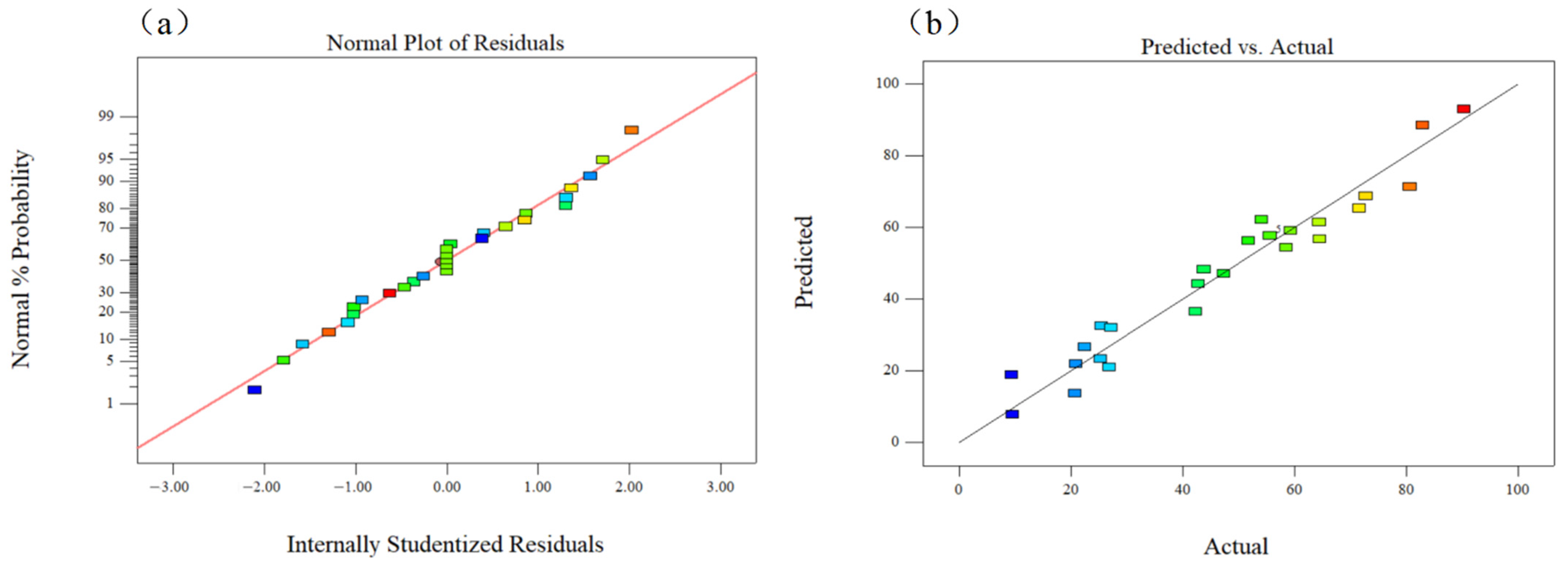
The significance of experimental factors was judged by F-value and p-value in ANOVA analysis, F-value was the accuracy of generated quadratic polynomial equation computed statistically, and the experimental factor was significant when the p-value < 0.05. The ANOVA results for response surface of the quadratic model were listed in Table 3. MO independent variable of time (A and A2), voltage (B and B2), discharge gap (C2), discharge needle numbers (D), and the interaction of AB were significant for the removal efficiency. However, the interaction of AC, AD, BC, BD, and CD were insignificant, and the independent variable of C and D2 were also insignificant. Therefore, the influence parameters for the MO by the plasma technique followed the order of time (A) ≈ voltage (B) > discharge needle numbers (D) > discharge gap (C). The Predicted R2 = 0.7119 was in reasonable agreement with the Adjusted R2 = 0.9000 because the difference < 0.2. The signal of noise ratio about Adep Precision = 16.954 > 4 demonstrating that the signal was acceptable due to among the desirable region. According to the parameters of p-value < 0.0001, R2 = 0.9500, which demonstrated the prediction model was appropriate for describing the plasma experimental data. As shown in Figure 5a, all residuals spread along a straight line that demonstrated a normal probability distribution plot of MO obtained removal rates which were employed to validate the normality of studentized residuals. Furthermore, Figure 5b correspondingly exhibited the predict and actual values of removal rates as another confirmation.
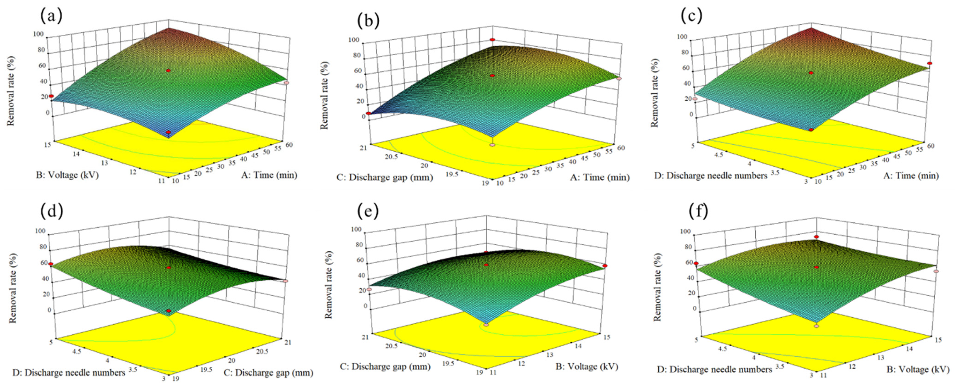
The RSM for the removal rates of MO according to the four important parameters achieved from the plasma experiment were presented in Figure 6a–f. Four parameters were demonstrated in 3D surface plots. The interactions among the voltage, time, discharge gap, as well as discharge needle numbers were correlated to the ANOVA results for response surface of quadratic model. In addition, when the removal rate of MO was predicted as 99.3% by massive optimization values in software, correspondingly, the optimum conditions including the voltage of 14.8 kV, the plasma treatment time of 60 min, the discharge gap of 20 mm, discharge needles of 5 were confirmed. This conclusion demonstrated that the results of RSM experiment conditions were consistent with the results of previous single-factor experiment conditions. Moreover, the regression model could be conformed as a second-order response surface by the fitting analysis of multi-linear regression, as shown in the following Equation (10).
Y = 59.24 + 25.60A + 11.88B + 0.68C + 9.22D + 8.24AB + 6.22AC + 4.63A − D − 4.37BC − 5.85BD −
3.28CD − 8.17A2 − 8.16B2 − 12.12C2 + 2.54D2
3.28CD − 8.17A2 − 8.16B2 − 12.12C2 + 2.54D2
3.5. Advantages of Removal Effect of MO in Novel Plasma Reactor
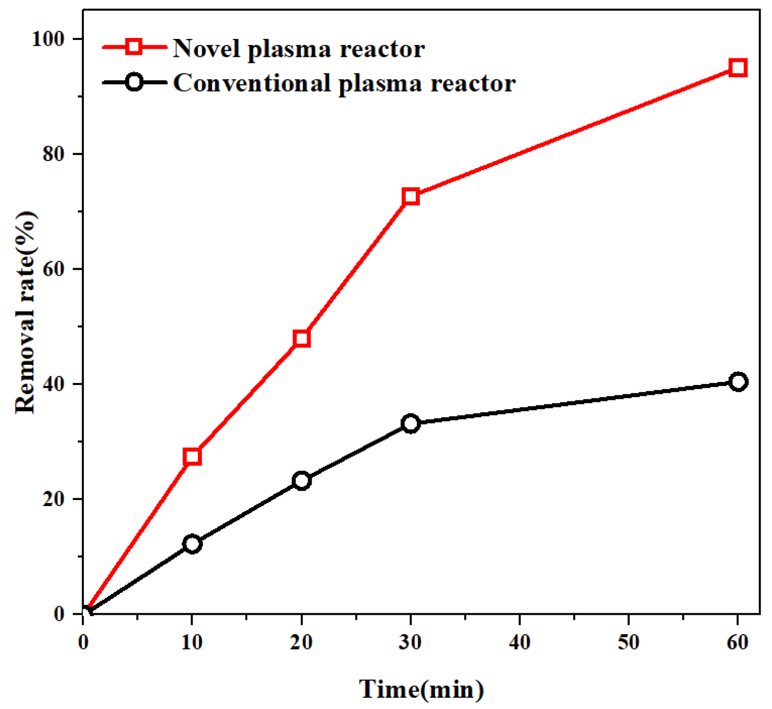
In order to verify the advantages of novel designed plasma reactor, the comparison of MO removal efficiencies applied with the same voltage of 15 kV was implemented between the novel and conventional plasma reactors (Figure S1). As shown in the Figure 7, the optimum removal rate of the novel plasma reactor could reach 95.1% at 60 min, while that of the conventional plasma reactor was only 40.5%. In addition, the energy consumption of the novel reactor for MO removal was only 0.26 kWh/g, which was much lower than that of the conventional plasma reactor with 1.1 kWh/g significantly. This might be related to the increased plasma area between the diameters of the grounded plate and the plasma discharge area, contributing to fully propagated plasma that occupied a roughly circular region on the gas-liquid surface with uniform leader distribution [33], furthermore, increasing the mass transfer efficiency and interaction between the active species and MO contaminant. Therefore, the novel designed plasma reactor could show both advantages of higher removal efficiency and lower energy consumption during the process of MO removal treatment.
3.6. The Influence of Catalysts on MO
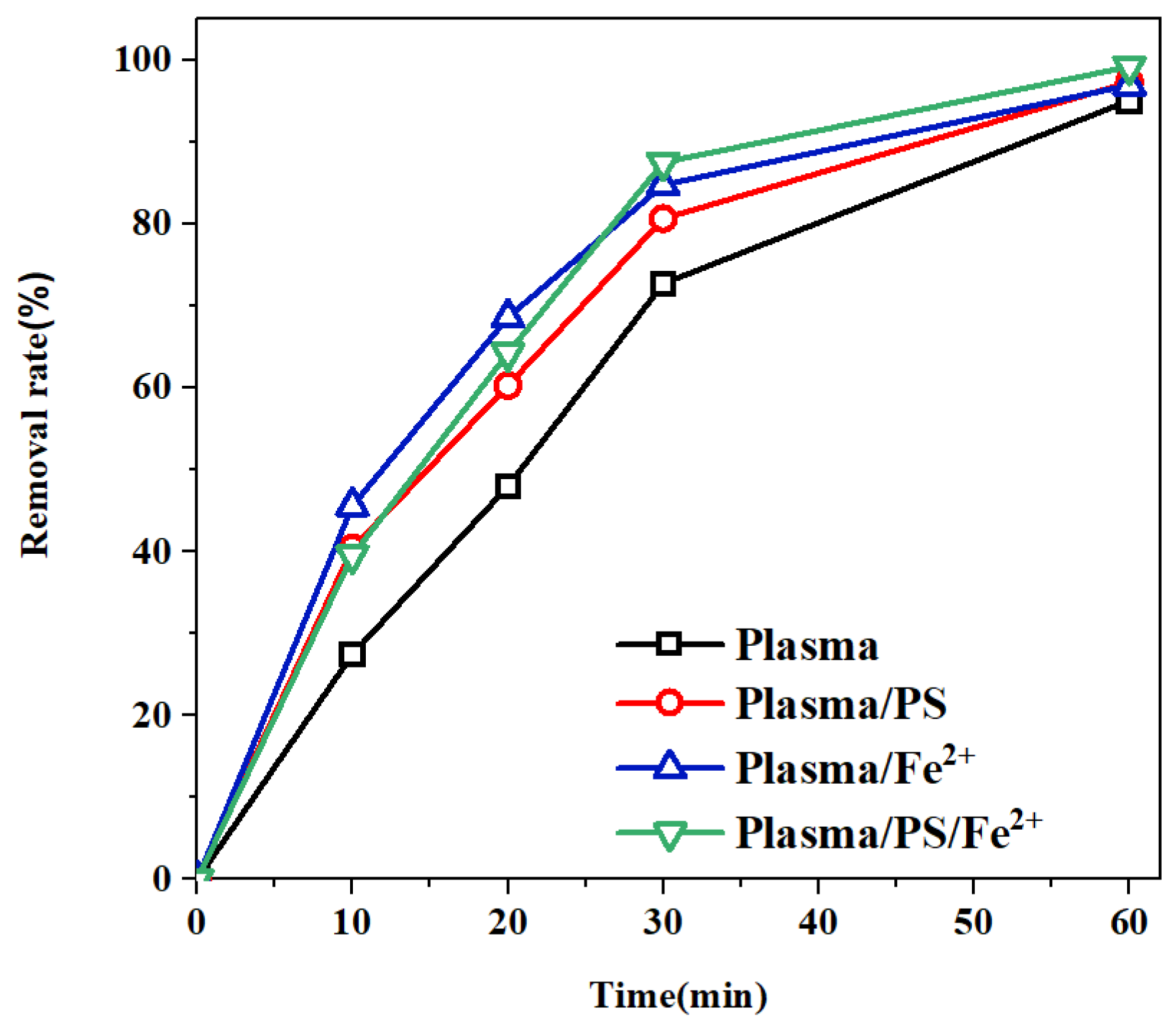
The MO removal efficiency could be further improved by adding catalysts due to the rapid interaction between active species and organic contaminants. For instance, Fe2+ could react with H2O2 in a solution, similarly to the Fenton reaction, to produce supplementary HO• [49], which was beneficial to improve the removal of organic matter greatly. PS could be easily activated by UV and heated by plasma, resulting in oxidizing to SO4•− strongly [50]. SO4•− showed a commendable oxidization effect on the improvement of degradation efficiency due to the advantages of strong stability [51]. Therefore, it is necessary to explore the influence of catalysts of PS and Fe2+ in the same experimental conditions optimized by RSM. As shown in Figure 8, four plasma system involving plasma, plasma/Fe2+, plasma/PS, and plasma/Fe2+/PS altogether performed remarkable treatment efficiency, and plasma/PS/Fe2+ exhibited the maximum removal rate for MO up to 99.2% at 60 min. The removal rates of MO could reach 97.0% and 97.3% under the plasma/Fe2+ system and plasma/PS system, respectively, when the concentration of Fe2+ and PS was both 0.02 mmol/L. Compared with the single plasma system, their removal rates of MO were enhanced slightly. This phenomenon might be related to the advanced oxidation of catalysts addition. For one thing, Fe2+ could efficiently catalyze H2O2 into advanced oxidation radical of HO• by the Fenton reaction, whereafter this active HO• could strengthen the removal efficiency of MO, as shown in Equations (11) and (12) [52]. For the other thing, as shown in Equation (13), PS could be activated by plasma to produce SO4•− radical [16,50], thus the removal rate of MO was enhanced by the SO4•− radical attack on the MO molecules efficiently. However, compared with the plasma/PS system, the plasma/Fe2+ system presented higher removal velocity. It was because that Fe2+ could catalyze H2O2 into a large number of active HO• radicals in a short time [29]. In addition, HO• was a nonselective radical with the oxidation potential of E0 = 1.8–2.7 V, which inclined to breakdown –N=N– bond of MO with low bond energy into a single structure resulting in decoloring initially. Whereas, SO4•− radical was a strong one-electron oxidant that would degrade aromatics selectively due to its higher oxidation potential of E0 = 2.5–3.1 V [24,53,54]. Moreover, XTOC of plasma/Fe2+ and plasma/PS system at 60 min were 16.1% and 20.7%, respectively. Higher XTOC presented by plasma/PS carried out further efforts to mineralize MO resulting in lower removal velocity. This also could explain the optimum removal efficiency of plasma/PS/Fe2+ system was attributable to the simultaneously synergistic reaction of HO• and SO4•−.
3.7. Removal Mechanism of Plasma for MO Removal
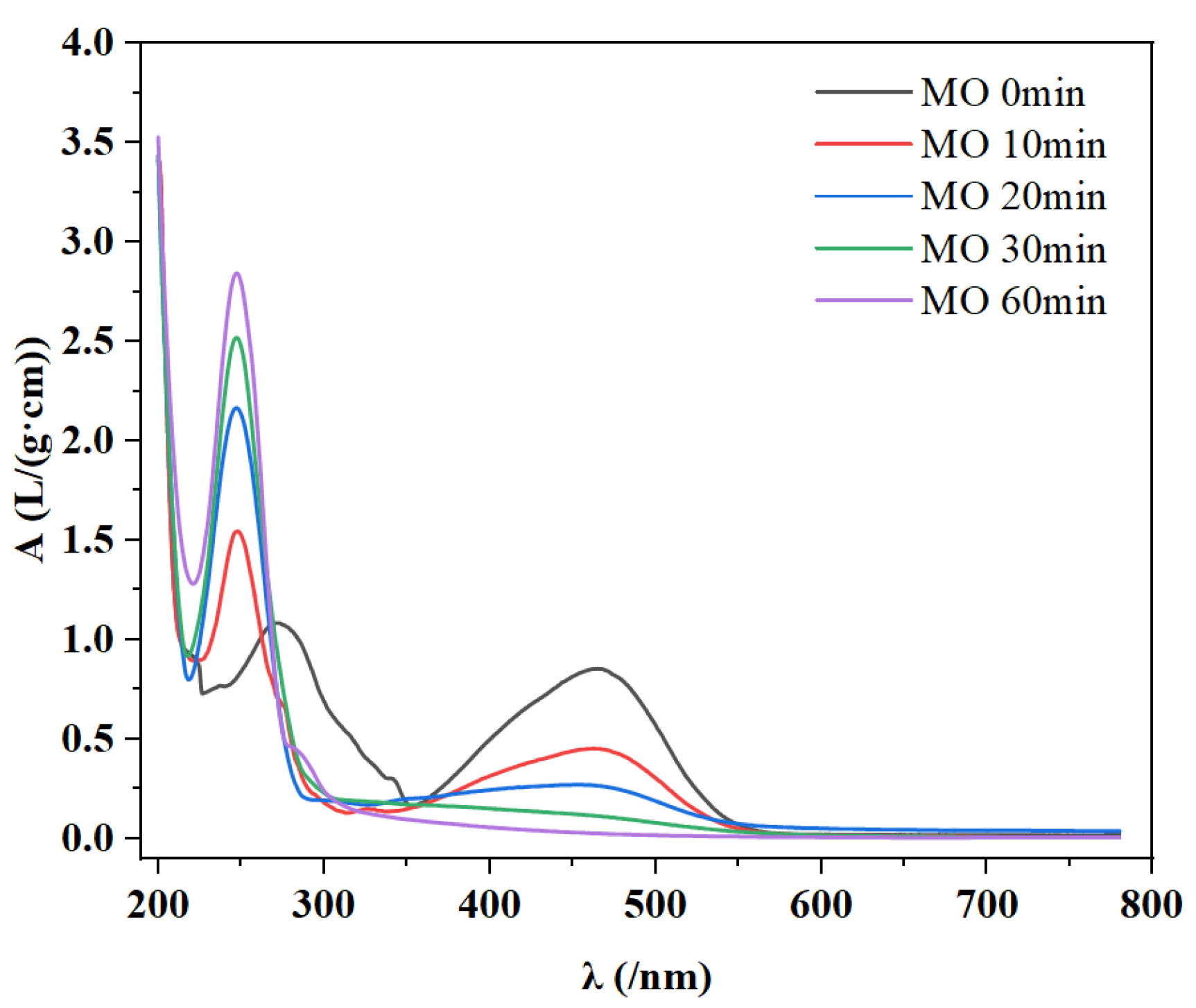
The MO removal mechanism was proposed by the UV-Vis spectrophotometry analysis between 200 and 900 nm in the optimal experiment conditions during the plasma treatment process. As shown in Figure 9, the initial MO solution presented two absorption peaks of 268 nm and 463 nm. The maximum absorption at 463 nm corresponded to the π-π conjugated chain of the –N=N– structure, and the other one at 268 nm corresponded to the characteristic absorption peak of the benzene ring [13].
With the reaction proceeding, the wavelength of MO at 463 nm was diminished gradually, which demonstrated the decrease of MO concentration. However, the wavelength of the benzene ring monomer at 268 nm was amplified progressively, possibly because the strong π-π conjugated system between –N=N–might be destroyed by HO• and O• in the plasma treatment process, thereafter MO was degraded into SO3 and phenylsulfinate ions [24]. Moreover, the peak of MO at 268 nm occurred blue shift slightly, demonstrating the obvious characteristic absorption peak of benzene ring. This phenomenon might be related to the occurrence of new productions involving monomer compounds of benzenesulfonic acid and phenolsulfonic acid [55], due to the MO oxidized by large amounts of free radicals generated during the plasma treatment.
4. Conclusions
In summary, the removal of MO in the simulated wastewater by novel plasma technique could be feasible. Intensive studies on simulated aqueous solutions containing MO were implemented on the conditions of removal treatment involving the voltage, the numbers of discharge needle, and the distances of discharge gap. The optimal removal rates for MO could achieve 95.1% with novel plasma reactor, when the treatment duration was 60 min, the voltage was set at 15 kV, discharge gap as 20 mm, and discharge needle numbers were 5, respectively. An accurate predicted method of RSM was established to optimize the plasma treatment process for the removal of MO from simulated wastewater with the four important influencing parameters above involved. The influence factors for MO removal followed the order of time and voltage > discharge needle numbers > discharge gap. The removal rate of MO was predicted as 99.3% by optimization values in software, the optimum conditions were confirmed as the voltage of 14.8 kV, the plasma treatment time of 60 min, the discharge gap of 20 mm, and discharge needle numbers of 5. Compared with the conventional reactor, the novel plasma reactor showed the advantages of high removal efficiency and low energy consumption for MO removal. The investigations of plasma associated with catalysts systems revealed the optimal removal rate for MO achieved 99.2% at 60 min by plasma/PS/Fe2+ system due to simultaneous synergistic reaction of HO• and SO4•−. Furthermore, through analyzing the variation in the absorbances with UV-Vis spectrophotometry during plasma process for the MO removal, it was found that –N=N– bond was initially attacked and broken by active species like HO•, and the oxidized intermediates of benzenesulfonic acid and phenolsulfonic acid might be generated. As a result, the present study demonstrated the excellent and efficient removal for MO through novel plasma treatment technique, and extensive investigations about novel plasma reactor design to improve mineralization rate should be further implemented in the future.
Supplementary Materials
The following supporting information can be downloaded at: https://www.mdpi.com/article/10.3390/w14193152/s1, Figure S1: The sketch map of conventional plasma reactor.
Author Contributions
Conceptualization, Y.L. and J.B.; Data curation, Y.L., J.-W.S. and C.-L.L.; Formal analysis, J.-W.S., C.-L.L. and L.-X.S.; Funding acquisition, J.B.; Investigation, J.-W.S., X.-J.S. and X.W.; Methodology, Y.L. and J.B.; Project administration, Y.L. and J.B.; Resources, Y.L. and J.B.; Software, J.-W.S. and L.-X.S.; Supervision, Y.L., J.B., X.-J.S. and X.W.; Validation, J.-W.S. and X.-J.S.; Visualization, L.-X.S.; Writing—original draft, Y.L. and J.-W.S.; Writing—review & editing, Y.L. and J.B. All authors have read and agreed to the published version of the manuscript.
Funding
This research was funded by the National Natural Science Foundation of China (No. 21976124 and No. 21507092), the Natural Science Foundation of Liaoning Province of China (No. 2019-ZD-0217), and Liaoning Revitalization Talents Program (No. XLYC2007195).
Data Availability Statement
Not applicable.
Conflicts of Interest
The authors declare no conflict of interest.
References
- Jamee, R.; Siddique, R. Biodegradation of Synthetic Dyes of Textile Effluent by Microorganisms: An Environmentally and Economically Sustainable Approach. Eur. Microbiol. Immu. 2019, 9, 114–118. [Google Scholar] [CrossRef] [PubMed]
- Ajaz, M.; Shakeel, S.; Rehman, A. Microbial use for azo dye degradation-a strategy for dye bioremediation. Int. Microbiol. 2020, 23, 149–159. [Google Scholar] [CrossRef]
- Selvaraj, V.; Karthika, T.S.; Mansiy, C.; Alagar, M. An over review on recently developed techniques, mechanisms and intermediate involved in the advanced azo dye degradation for industrial applications. J. Mol.Struct. 2021, 1224, 129195. [Google Scholar] [CrossRef]
- Fatima, M.; Farooq, R.; Lindstrom, R.W.; Saeed, M. A review on biocatalytic decomposition of azo dyes and electrons recovery. J. Mol. Liq. 2017, 246, 275–281. [Google Scholar] [CrossRef]
- Chung, K.T. Azo dyes and human health: A review. J. Environ. Sci. Health C 2016, 4, 233–261. [Google Scholar] [CrossRef] [PubMed]
- Pirkarami, A.; Olya, M.E.; Limaee, N.Y. Decolorization of azo dyes by photo electro adsorption process using polyaniline coated electrode. Prog. Org. Coat. 2013, 76, 682–688. [Google Scholar] [CrossRef]
- Yaseen, D.A.; Scholz, M. Textile dye wastewater characteristics and constituents of synthetic effluents: A critical review. Int. J. Environ. Sci. Technol. 2019, 16, 1193–1226. [Google Scholar] [CrossRef] [Green Version]
- Dahiya, D.; Nigam, P.S. Waste Management by Biological Approach Employing Natural Substrates and Microbial Agents for the Remediation of Dyes’ Wastewater. Appl. Sci. 2020, 10, 2958. [Google Scholar] [CrossRef]
- Donkadokula, N.Y.; Kola, A.K.; Naz, I.; Saroj, D. A review on advanced physico-chemical and biological textile dye wastewater treatment techniques. Rev. Environ. Sci. Biotechnol. 2020, 19, 543–560. [Google Scholar] [CrossRef]
- Li, C.; Zhang, M.H.; Song, C.W.; Tao, P.; Sun, M.H.; Shao, M.H.; Wang, T.H. Enhanced Treatment Ability of Membrane Technology by Integrating an Electric Field for Dye Wastewater Treatment: A Review. J. Aoac. Int. 2018, 101, 1341–1352. [Google Scholar] [CrossRef] [PubMed]
- Katheresan, V.; Kanseto, J.; Lau, S.Y. Efficiency of various recent wastewater dye removal methods: A review. J. Environ. Chem. Eng. 2018, 6, 4676–4697. [Google Scholar] [CrossRef]
- Perez, A.; Poznyak, T.; Chairez, I.; Guzman-Zavaleta, Z.J.; Alfaro-Ponce, M. Influence of Sodium Sulfate on the Direct Red 28 Degradation by Ozone in a Wastewater Recycling Process: A Stoichiometric and Novel Image Analysis. Mater. Lett. 2019, 42, 428–438. [Google Scholar] [CrossRef]
- Liu, Y.; Li, C.L.; Bao, J.; Wang, X.; Yu, W.J.; Shao, L.X. Degradation of Azo Dyes with Different Functional Groups in Simulated Wastewater by Electrocoagulation. Water 2022, 14, 123. [Google Scholar] [CrossRef]
- Shanker, U.; Rani, M.; Jassal, V. Degradation of hazardous organic dyes in water by nanomaterials. Environ. Chem. Lett. 2017, 15, 623–642. [Google Scholar] [CrossRef]
- Jiang, B.; Zheng, J.T.; Qiu, S.; Wu, M.B.; Zhang, Q.H.; Yan, Z.F.; Xue, Q.Z. Review on electrical discharge plasma technology for wastewater remediation. J. Colloid Interface Sci. 2014, 236, 348–368. [Google Scholar] [CrossRef]
- Fan, J.W.; Wu, H.X.; Liu, R.Y.; Meng, L.Y.; Sun, Y.J. Review on the treatment of organic wastewater by discharge plasma combined with oxidants and catalysts. Environ. Sci. Pollut. R. 2021, 28, 2522–2548. [Google Scholar] [CrossRef] [PubMed]
- Shang, K.F.; Li, J.; Morent, R. Hybrid electric discharge plasma technologies for water decontamination: A short review. Plasma. Sci. Technol. 2019, 21, 043001. [Google Scholar] [CrossRef]
- Cui, M.H.; Liu, W.Z.; Cui, D. Recent advancements in azo dye decolorization in bio-electrochemical systems (BESs): Insights into decolorization mechanism and practical application. Water Res. 2021, 203, 117512. [Google Scholar] [CrossRef] [PubMed]
- Goncharuk, W.; Klishchenko, R.E.; Kornienko, I.V. Destruction of GT Azo Active Orange Dye in the Flow-Through Plasma-Chemical Reactor. J. Water Chem. Technol. 2018, 40, 185–189. [Google Scholar] [CrossRef]
- Sen, S.K.; Raut, S.; Bandyopadhyay, P.; Raut, S. Fungal decolouration and degradation of azo dyes: A review. Fungal. Biol. Rev. 2016, 30, 112–133. [Google Scholar] [CrossRef]
- Topolovec, B.; Skoro, N.; Puac, N.; Petrovic, M. Pathways of organic micropollutants degradation in atmospheric pressure plasma processing -A review. Chemosphere 2022, 294, 133606. [Google Scholar] [CrossRef]
- Russo, M.; Lervolino, G.; Vaiano, V.; Palma, V. Non-Thermal Plasma Coupled with Catalyst for the Degradation of Water Pollutants: A Review. Catalysts 2020, 10, 1438. [Google Scholar] [CrossRef]
- Magureanu, M.; Bradu, C.; Parvulescu, V.I. Plasma processes for the treatment of water contaminated with harmful organic compounds. J. Phys. D Appl. Phys. 2018, 51, 313002. [Google Scholar] [CrossRef]
- Ma, S.; Lee, S.; Kim, K.; Im, J.; Jeon, H. Purification of organic pollutants in cationic thiazine and azo dye solutions using plasma-based advanced oxidation process via submerged multi-hole dielectric barrier discharge. Sep. Purif. Technol. 2021, 255, 117715. [Google Scholar] [CrossRef]
- Sarangapani, C.; Dixit, Y.; Milosavljevic, V.; Bourke, P.; Sullivan, C.; Cullen, P.J. Optimization of atmospheric air plasma for degradation of organic dyes in wastewater. Water Sci. Technol. 2017, 75, 207–219. [Google Scholar] [CrossRef]
- Wu, L.H.; Xie, Q.L.; Lv, Y.B.; Wu, Z.Y.; Liang, X.J.; Lu, M.Z.; Nie, Y. Degradation of Methylene Blue via Dielectric Barrier Discharge Plasma Treatment. Water 2019, 11, 1818. [Google Scholar] [CrossRef] [Green Version]
- Koppenol, W.H. Names for inorganic radicals (IUPAC recommendations 2000). Pure. Appl. Chem. 2000, 72, 437–446. [Google Scholar] [CrossRef] [Green Version]
- Essiptchouk, A.; Petraconi, G.; Miranda, F.; Saraiva, A.C.V.; Charakhovski, L. Glycerine degradation by submerged plasma. J. Phys. D Appl. Phys. 2019, 52, 465201. [Google Scholar] [CrossRef]
- Shang, K.F.; Li, W.F.; Wang, X.J.; Lu, N.; Jiang, N.; Li, J. Degradation of p-nitrophenol by DBD plasma/Fe2+/persulfate oxidation process. Sep. Purif. Technol. 2019, 218, 106–112. [Google Scholar] [CrossRef]
- Chen, W.M.; Gu, Z.P.; Guo, S.P.; Li, Q.B. Microwave-assisted Fe-0-activated persulfate process for treating explosives in production wastewater. Chem. Eng. J. 2020, 391, 123497. [Google Scholar] [CrossRef]
- Peng, J.B.; Wang, Z.X.; Wang, S.Y.; Liu, J.; Zhang, Y.Z.; Wang, B.J.; Gong, Z.M.; Wang, M.J.; Dong, H.; Shi, J.L. Enhanced removal of methylparaben mediated by cobalt/carbon nanotubes (Co/CNTs) activated peroxymonosulfate in chloride-containing water: Reaction kinetics, mechanisms and pathways. Chem. Eng. J. 2021, 409, 128176. [Google Scholar] [CrossRef]
- Qi, C.D.; Wen, Y.N.; Zhao, Y.J.; Dai, Y.H.; Li, Y.P.; Xu, C.M.; Yang, S.G.; He, H. Enhanced degradation of organic contaminants by Fe(III)/peroxymonosulfate process with L-cysteine. Chin. Chem. Lett. 2022, 33, 2125–2128. [Google Scholar] [CrossRef]
- Stratton, G.R.; Bellona, C.L.; Dai, F.; Holsen, T.M.; Thagard, S.M. Plasma-based water treatment: Conception and application of a new general principle for reactor design. Chem. Eng. J. 2015, 273, 543–550. [Google Scholar] [CrossRef]
- Oke, S.R.; Ige, O.O.; Falodun, O.E.; Okoro, A.M.; Mphahlele, M.R.; Olubambi, P.A. Powder metallurgy of stainless steels and composites: A review of mechanical alloying and spark plasma sintering. Int. J. Adv. Manuf. Tech. 2019, 102, 3271–3290. [Google Scholar] [CrossRef]
- Zhang, C.X.; Sun, Y.B.; Yu, Z.Q.; Zhang, G.Y.; Feng, J.W. Simultaneous removal of Cr(VI) and acid orange 7 from water solution by dielectric barrier discharge plasma. Chemosphere 2018, 191, 527–536. [Google Scholar] [CrossRef]
- Zhang, C.; Qiu, J.T.; Kong, F.; Hou, X.M.; Fang, Z.; Yin, Y.; Shao, T. Plasma surface treatment of Cu by nanosecond-pulse diffuse discharges in atmospheric air. Plasma. Sci. Technol. 2018, 20, 014001. [Google Scholar] [CrossRef]
- Sun, B.; Aye, N.N.; Gao, Z.Y.; Lv, D.; Zhu, X.M.; Sato, M. Characteristics of gas-liquid pulsed discharge plasma reactor and dye decoloration efficiency. J. Environ. Sci. 2012, 24, 840–845. [Google Scholar] [CrossRef]
- Kakhki, R.M.; Rahni, S.Y.; Karimian, A. Removal of Methyl Orange from aqueous solutions by a novel, high efficient and low cost copper-modified nanoalum. Inorg. Nano-Met. Chem. 2021, 51, 1291–1296. [Google Scholar]
- Ko, S.J.; Yamaguchi, T.; Salles, F.; Oh, J.M. Systematic utilization of layered double hydroxide nanosheets for effective removal of Methyl Orange from an aqueous system by pi-pi stacking-induced nanoconfinement. J. Environ. Manag. 2021, 277, 111455. [Google Scholar] [CrossRef]
- Bagheri, F.; Chaibakhsh, N. Efficient visible-light photocatalytic ozonation for dye degradation using Fe2O3/MoS2 nanocomposite. Sep. Sci. Technol. 2021, 56, 3022–3032. [Google Scholar] [CrossRef]
- Meiyazhagan, S.; Yugeswaran, S.; Ananthapadmanabhan, P.V.; Suresh, K. Process and kinetics of dye degradation using microplasma and its feasibility in textile effluent detoxification. J. Water Process Eng. 2020, 37, 101519. [Google Scholar] [CrossRef]
- Hafeez, A.; Javed, F.; Fazal, T.; Shezaed, N.; Amjad, U.E.S.; Rehman, M.S.U. Intensification of ozone generation and degradation of azo dye in non-thermal hybrid corona-DBD plasma micro-reactor. Chem. Eng. Processing 2021, 159, 108205. [Google Scholar] [CrossRef]
- Takahashi, K.; Takeda, M.; Konno, R.; Takaki, K.; Satta, N. Influence of Electric Parameters on Hydroxyl Radical Production by Positive Pulsed Discharge Inside of a Bubble in Water. IEEE Trans. Plasma Sci. 2019, 47, 1105–1113. [Google Scholar] [CrossRef]
- Guo, H.; Wang, Y.W.; Liao, L.N.; Li, Z.; Pan, S.J.; Puyang, C.D.; Su, Y.Y.; Zhang, Y.; Wang, T.C.; Ren, J.Y. Review on remediation of organic-contaminated soil by discharge plasma: Plasma types, impact factors, plasma-assisted catalysis, and indexes for remediation. Chem. Eng. J. 2022, 436, 135239. [Google Scholar] [CrossRef]
- Hu, X.Y.; Wang, B.W. Removal of pefloxacin from wastewater by dielectric barrier discharge plasma: Mechanism and degradation pathways. J. Environ. Chem. Eng. 2021, 9, 105720. [Google Scholar] [CrossRef]
- Lee, H.D.; Kim, J.O.; Chung, J.W. Degradation of Methyl Orange by pulsed corona discharge process in water. Desalin. Water Treat. 2015, 53, 2767–2773. [Google Scholar] [CrossRef]
- Xiang, H.J.; Lei, B.; Yuan, X.C.; Lv, Q.A.; Zhang, Q. Design and Simulation of New Type Reactor in the Wastewater Treatment System Based on Discharge Plasma. IEEE Trans. Plasma Sci. 2019, 47, 952–957. [Google Scholar] [CrossRef]
- Jadaa, W.; Prakash, A.; Ray, A.K. Modeling of Degradation of Diazo Dye in Swirl-Flow Photocatalytic Reactor: Response Surface Approach. Catalysts 2020, 10, 1418. [Google Scholar] [CrossRef]
- Wang, J.K.; Yao, Z.P.; Wang, Y.J.; Xia, Q.X.; Chu, H.Y.; Jiang, Z.H. Preparation of immobilized coating Fenton-like catalyst for high efficient degradation of phenol. Environ. Pollut. 2017, 224, 552–558. [Google Scholar] [CrossRef]
- Liu, Y.; Qu, G.Z.; Sun, Q.H.; Jia, H.Z.; Wang, T.C.; Zhu, L.Y. Endogenously activated persulfate by non-thermal plasma for Cu(II)-EDTA decomplexation: Synergistic effect and mechanisms. Chem. Eng. J. 2021, 406, 126774. [Google Scholar] [CrossRef]
- Yang, D.Z.; Zhou, X.F.; Liang, J.P.; Xu, Q.N.; Wang, H.L.; Yang, K.; Wang, B.; Wang, W.C. Degradation of methylene blue in liquid using high-voltage pulsed discharge plasma synergizing iron-based catalyst-activated persulfate. J. Phys. D Appl. Phys. 2021, 54, 244002. [Google Scholar] [CrossRef]
- Li, H.; Song, R.Y.; Wang, Y.Y.; Zhong, R.W.; Zhang, Y.; Zhou, J.; Wang, T.C.; Zhu, L.Y. Simultaneous removal of antibiotic-resistant bacteria and its resistance genes in water by plasma oxidation: Highlights the effects of inorganic ions. Sep. Purif. Technol. 2022, 218, 119672. [Google Scholar] [CrossRef]
- Yuan, R.X.; Ramjaun, S.N.; Wang, Z.H.; Liu, J.S. Effects of chloride ion on degradation of Acid Orange 7 by sulfate radical-based advanced oxidation process: Implications for formation of chlorinated aromatic compounds. J. Hazard. Mater. 2011, 196, 173–179. [Google Scholar] [CrossRef] [PubMed]
- Das, S.; Kamat, P.V.; Padmaja, S.; Au, V.; Madison, S.A. Free radical induced oxidation of the azo dye Acid Yellow 9. J. Chem. Soc. Perkin Trans. 2 1999, 6, 1219–1223. [Google Scholar] [CrossRef]
- Wang, B.W.; Xu, M.; Chi, C.M.; Chao, W.; Dajun, M.J. Degradation of Methyl Orange using dielectric barrier discharge water falling film reactor. J. Adv. Oxid. Technol. 2017, 20, 20170021. [Google Scholar] [CrossRef]
Figure 1.
The sketch map of a novel plasma reactor. (1. Air vent 2. Sample collection hole 3. Grounded electrode plate 4. Discharge electrode plate 5. Discharge needle 6. Nylon column 7. Power lead 8. Ground lead).
Figure 1.
The sketch map of a novel plasma reactor. (1. Air vent 2. Sample collection hole 3. Grounded electrode plate 4. Discharge electrode plate 5. Discharge needle 6. Nylon column 7. Power lead 8. Ground lead).

Figure 2.
The influence of voltage on the removal rate of MO.

Figure 3.
The influence of discharge gap on removal rate of MO.

Figure 4.
The influence of discharge needles number on removal rate of MO.

Figure 5.
The normal probability plot of studentized residuals of MO of the model for the removal rates (a) and the experimental response values versus the predicted response value of MO removal rates (b).
Figure 5.
The normal probability plot of studentized residuals of MO of the model for the removal rates (a) and the experimental response values versus the predicted response value of MO removal rates (b).

Figure 6.
RSM for degradation efficiency of MO as a function of voltage and time (a), discharge gap and time (b), discharge needle numbers and time (c), discharge needle numbers and discharge gap (d), discharge gap and voltage (e), discharge needle numbers and voltage (f).
Figure 6.
RSM for degradation efficiency of MO as a function of voltage and time (a), discharge gap and time (b), discharge needle numbers and time (c), discharge needle numbers and discharge gap (d), discharge gap and voltage (e), discharge needle numbers and voltage (f).

Figure 7.
The comparison of novel and conventional reactor for the removal rates of MO (the novel plasma reactor (V = 50 mL) and the conventional plasma reactor (V = 150 mL) under the same conditions of initial concentration = 100 mg/L, voltage = 15 kV, discharge gap = 20 mm, and discharge needle numbers = 5).

Figure 8.
The removal rates of MO under plasma, plasma/PS, plasma/Fe2+ and plasma/PS/Fe2+ systems.

Figure 9.
Absorbance spectra of MO solution over the reaction time.


Table 1.
Response surface factor level table in novel plasma reactor.
| Parameter | Horizontal Extent | ||
|---|---|---|---|
| −1 | 0 | 1 | |
| Time (min) | 10 | 35 | 60 |
| Voltage (kV) | 11 | 13 | 15 |
| Discharge gap (mm) | 19 | 20 | 21 |
| Discharge needle numbers | 3 | 4 | 5 |
Table 2.
Results of the removal experiment of MO.
| The Experimental Number | Time (min) | Voltage (kV) | Discharge Gap (mm) | Discharge Needle Numbers | Removal Rate (%) |
|---|---|---|---|---|---|
| 1 | 60.00 | 13.00 | 20.00 | 3.00 | 71.52 |
| 2 | 10.00 | 13.00 | 21.00 | 4.00 | 9.54 |
| 3 | 60.00 | 13.00 | 20.00 | 5.00 | 90.25 |
| 4 | 35.00 | 15.00 | 20.00 | 5.00 | 72.73 |
| 5 | 35.00 | 13.00 | 19.00 | 5.00 | 64.4 |
| 6 | 10.00 | 15.00 | 20.00 | 4.00 | 26.84 |
| 7 | 60.00 | 11.00 | 20.00 | 4.00 | 43.77 |
| 8 | 10.00 | 13.00 | 20.00 | 3.00 | 25.26 |
| 9 | 35.00 | 11.00 | 20.00 | 5.00 | 64.53 |
| 10 | 60.00 | 13.00 | 21.00 | 4.00 | 80.59 |
| 11 | 35.00 | 15.00 | 20.00 | 3.00 | 54.08 |
| 12 | 60.00 | 13.00 | 19.00 | 4.00 | 55.58 |
| 13 | 35.00 | 11.00 | 19.00 | 4.00 | 20.88 |
| 14 | 35.00 | 13.00 | 20.00 | 4.00 | 59.24 |
| 15 | 10.00 | 11.00 | 20.00 | 4.00 | 20.76 |
| 16 | 10.00 | 13.00 | 19.00 | 4.00 | 9.41 |
| 17 | 35.00 | 15.00 | 21.00 | 4.00 | 47.34 |
| 18 | 35.00 | 13.00 | 20.00 | 4.00 | 59.24 |
| 19 | 10.00 | 13.00 | 20.00 | 5.00 | 25.49 |
| 20 | 35.00 | 13.00 | 19.00 | 3.00 | 42.35 |
| 21 | 35.00 | 13.00 | 20.00 | 4.00 | 59.24 |
| 22 | 35.00 | 11.00 | 21.00 | 4.00 | 27.24 |
| 23 | 35.00 | 15.00 | 19.00 | 4.00 | 58.45 |
| 24 | 35.00 | 13.00 | 21.00 | 3.00 | 42.78 |
| 25 | 35.00 | 13.00 | 20.00 | 4.00 | 59.24 |
| 26 | 35.00 | 11.00 | 20.00 | 3.00 | 22.48 |
| 27 | 60.00 | 15.00 | 20.00 | 4.00 | 82.83 |
| 28 | 35.00 | 13.00 | 21.00 | 5.00 | 51.7 |
Table 3.
MO ANOVA results for response surface of quadratic model.
| Source | Sum of Squares | df | Mean Square | F-Value | p-Value | |
|---|---|---|---|---|---|---|
| Model | 13,001.19 | 14 | 928.66 | 18.99 | <0.0001 | significant |
| A-Time | 7866.37 | 1 | 7866.37 | 160.89 | <0.0001 | |
| B-Voltage | 1694.80 | 1 | 1694.80 | 34.66 | <0.0001 | |
| C-discharge gap | 5.49 | 1 | 5.49 | 0.11 | 0.7424 | |
| D-discharge needle numbers | 1019.92 | 1 | 1019.92 | 20.86 | 0.0004 | |
| AB | 271.92 | 1 | 271.92 | 5.56 | 0.0334 | |
| AC | 154.75 | 1 | 154.75 | 3.17 | 0.0969 | |
| AD | 85.56 | 1 | 85.56 | 1.75 | 0.2071 | |
| BC | 76.30 | 1 | 76.30 | 1.56 | 0.2321 | |
| BD | 136.89 | 1 | 136.89 | 2.80 | 0.1165 | |
| CD | 43.10 | 1 | 43.10 | 0.88 | 0.3637 | |
| A2 | 443.32 | 1 | 443.32 | 8.86 | 0.0100 | |
| B2 | 432.13 | 1 | 432.13 | 8.84 | 0.0101 | |
| C2 | 952.96 | 1 | 952.96 | 19.49 | 0.0006 | |
| D2 | 41.94 | 1 | 41.94 | 0.86 | 0.3700 | |
| Residual | 684.49 | 14 | 48.89 | |||
| Lack of Fit | 684.49 | 10 | 68.45 | |||
| Pure Error | 0.000 | 4 | 0.000 | |||
| Cor Total | 13,685.68 | 28 |
R2 = 0.9500 Adjusted R2 = 0.9000 Predicted R2 = 0.7119 Adeq Presion = 16.954.
Publisher’s Note: MDPI stays neutral with regard to jurisdictional claims in published maps and institutional affiliations. |
© 2022 by the authors. Licensee MDPI, Basel, Switzerland. This article is an open access article distributed under the terms and conditions of the Creative Commons Attribution (CC BY) license (https://creativecommons.org/licenses/by/4.0/).
Share and Cite
MDPI and ACS Style
Liu, Y.; Song, J.-W.; Bao, J.; Shen, X.-J.; Li, C.-L.; Wang, X.; Shao, L.-X. Optimized Removal of Azo Dyes from Simulated Wastewater through Advanced Plasma Technique with Novel Reactor. Water 2022, 14, 3152. https://doi.org/10.3390/w14193152
AMA Style
Liu Y, Song J-W, Bao J, Shen X-J, Li C-L, Wang X, Shao L-X. Optimized Removal of Azo Dyes from Simulated Wastewater through Advanced Plasma Technique with Novel Reactor. Water. 2022; 14(19):3152. https://doi.org/10.3390/w14193152
Chicago/Turabian StyleLiu, Yang, Jia-Wei Song, Jia Bao, Xin-Jun Shen, Cheng-Long Li, Xin Wang, and Li-Xin Shao. 2022. "Optimized Removal of Azo Dyes from Simulated Wastewater through Advanced Plasma Technique with Novel Reactor" Water 14, no. 19: 3152. https://doi.org/10.3390/w14193152
Note that from the first issue of 2016, this journal uses article numbers instead of page numbers. See further details here.