
Flexible Electroflotocoagulation Reactor: New Design and Testing in Treatment of Real Surface Water


1
Department of Applied Chemistry and Engineering of Inorganic Compounds and Environment, Politehnica University of Timisoara, 300223 Timisoara, Romania
2
Department of Electrical Engineering, Politehnica University of Timisoara, 300223 Timisoara, Romania
3
Department of Design and Research, BeeSpeed Automatizari Ltd., 307221 Chisoda, Romania
*
Author to whom correspondence should be addressed.
Water 2022, 14(19), 2990; https://doi.org/10.3390/w14192990
Submission received: 12 August 2022
/
Revised: 7 September 2022
/
Accepted: 18 September 2022
/
Published: 23 September 2022
(This article belongs to the Section Wastewater Treatment and Reuse)
Abstract
:A novel continuous and flexible electroflotocoagulation (EFC) reactor was built using concentric cylindrical Al and Fe electrodes, which can be operated either as anodes or cathodes linked to a DC connection. The reactor was operationally assessed related to various cell configurations that assured the required stages of coagulant dosage, mixing, reaction, and settling or flotation. The effects of several design variables and operational parameters (such as the electrode position that determines the reactor configuration, current density (i), flow rate (F), and the electrode area-treated volume ratio (Sel/V)) on the specific energy consumption versus the aluminum dose and charge loading rate were investigated. The most energy-efficient cell configuration using an aluminum anode and iron cathode was tested for the treatment of surface water (Bega river, Timisoara city, Romania) rich in hydrophobic natural organic matter (8.3 mg C∙L−1 and specific UV absorbance parameter of 3.9 L∙m−1∙mg−1) and with a high turbidity of 92 NTU, under flood conditions. The best results that assured 97% turbidity removal, 87% for absorbance recorded at 254 nm, and 60% for DOC removal, through enhanced electroflotocoagulation, were achieved for an operational current density of 10 A∙m−2 with specific energy and electrode consumption of 0.1 kW h∙m−3 and 0.017 kg Al∙m−3, respectively.
1. Introduction
Electroflotocoagulation (EFC) reactors have been built in a variety of configurations, each being characterized by its own set of advantages and disadvantages, with different degrees of treatment ability. The performance assessment of different reactor configurations is very difficult because the reactor geometry affects the main operational parameters, including floc formation bubble path and size, fluid flow regime, and mixing or settling characteristics via the current density and cell voltage [1,2,3].
An EFC unit can be operated by two approaches. Sometimes, an EFC unit is used simply as a replacement for chemical dosing systems and does not always take advantage of the electrolytic gases produced and floc formation in the electrocoagulation process. In this situation, the downstream units for reaction and settling are required to generate and remove the pollutants containing sludge from the water. However, a complete unitary system consisting of an in situ dosage of reagents, mixing, reaction, and sludge settling can be considered for designing an EFC reactor.
Aluminum- or iron-based electrodes are commonly used in EFC units for wastewater or water treatment and various electrode geometries, e.g., horizontal [4,5], vertical [6], or cylindrical [7], in accordance with the reactor configuration, and different operation modes (batch or continuous) have been tested. In batch operation mode, the horizontal anode of iron reportedly allowed high efficiency for arsenic removal from real groundwater [4] and 70% of total organic carbon has been removed from surface water through aluminum anode under the same electrolytic cell configuration, with adapted operating conditions simulating conventional coagulation steps [5]. Alkhatib et al. (2020) studied the removal of total phosphorus (TP) and chemical oxygen demand (COD) from secondarily treated wastewater using unsymmetrical (cylindrical) aluminum electrodes. A TP removal of 89% and a COD removal of 82% were obtained after 30 min, using an AC power supply and 4.3 m∙A∙cm−2 [7].
Furthermore, the electrode arrangement and connection to polarization as monopolar and bipolar have been considered and compared. Golder et al. (2007) obtained a 99.9% removal of Cr3+ after 50 min of electrocoagulation using a bipolar arrangement and a 1A cell current compared to an 81.5% removal rate for a monopolar electrode configuration, using iron electrodes [6]. Another study conducted by Naje et al. (2016) concluded that, using Al as the electrode material in industrial wastewater, about 92% Cd removal efficiency was obtained using bipolar electrodes, compared to an 87% Cd removal efficiency obtained using monopolar electrodes [8]. A significant relationship between the reactor geometry and configuration and the removal of pollutants from wastewaters has been reported by Cruz et al. (2019), which highlighted the superiority of plate versus rod anodes and bipolar versus monopolar anodes [9].
The electrode surface-area–volume (Sel/V) ratio has been shown to be a significant scale-up parameter. The electrode area influences current density and rate of cation dosing, as well as bubble production and bubble path length. It has been reported that, as the Sel/V ratio increases, the optimal current density decreases for the same rate of the cation dosing [10]. It is obvious that the shape of the electrode influences the Sel/V ratio and the position in the reactor, which affects the performance of the electrocoagulation process. Khaled et al. (2019) concluded that increasing the Sel/V value from 3.4 to 13.6 m−1 led to an increase in Cd removal efficiency from 90.95% to 99.76%, together with a decrease in energy consumption from 10.2 to 1.75 kWh m−3 within 30 min of electrolysis time, using a monopolar connection mode [11]. Moreover, 100% zinc removal was achieved for the same Sel/V value using a bipolar connection mode [12].
Applying the EFC process to drinking water treatment can become a challenge considering the low conductivities found in most drinking water sources, which means higher resistivity between electrodes, implying higher operating potentials and power consumption. To overcome this limitation, salt must be adding to assure ionic strength demand, and if ion concentrations overcome the maximum limits, the EFC should be coupled with an appropriate process to remove ionic concentrations. However, the groundwater, as the source for drinking water treatment, is characterized by higher conductivity in comparison with the surface water, which makes it easier to treat by the EFC process, in accordance with their composition. Although EFC has its fundamental complications for drinking water treatment, it must be considered a potential variant of classical coagulation based on the advantage of the in situ production of the coagulant. This issue is very important for small and remote communities that are difficult to access, where localized is preferred over centralized water treatment technology; EFC should eliminate the chemical reagent transport that is necessary for conventional chemical coagulation, and unconventional energy can be used for process functioning, e.g., solar panels [13,14]. Few studies for Al- or Fe-based EFC testing for drinking water treatment on a lab scale have been reported [4,5,10]. However, Mameri et al. (1998) extended their study to a larger pilot-scale system, using aluminum bipolar electrodes and concluding that that flow rate and current represent the two main operational parameters affected by the process efficiency [10].
Research comparing conventional chemical coagulation using alum (aluminum sulphate) and aluminum in EFC for the removal of the turbidity associated with clay pollutants has also been investigated. It was found that alum coagulation provided more an effective reduction of turbidity under acidic conditions and low coagulant dosing. It was also found that at higher operating currents, pollutant removal occurred more quickly; however, higher pollutant concentration was removed per unit of Al introduced at lower operating currents [15]. Moreover, EFC is able to reduce waste production and the time necessary for treatment [16].
However, the approach of enhanced coagulation is considered in drinking water treatment to improve the removal of natural organic matter (NOM) as the main precursor to disinfection by-products (e.g., trihalomethane), which is carried out by adding excessive amounts of coagulation reagent [17].
Considering that an increased current density allows the improvement in removal efficiency by EFC [18,19,20] but causes a higher energy and electrode consumption [21], it is necessary to propose new and innovative reactor and electrode designs to improve the rate of overall EFC treatment times with a minimum energy and electrode consumption.
The aim of this study was to assess a new and flexible configuration of the electrochemical reactor linked to the geometry and type of anodes as a key factor in the operation optimization of an energy efficient electroflotocoagulation (EFC) reactor. By this approach, the assessment was achieved by considering that the electrochemical reactor includes all steps known in conventional coagulation: the metal ion dosing during the mixing stage, the reaction stage that assures the flotation, and the settling or flotation stage for sludge separation. Additionally, the electrode configuration that defines the reactor geometry and size is considered using an aluminum sacrificial anodes and iron cathodes. In this systematic study, the researchers considered the factors that are generally known as the main design variables and operational parameters that affect the EFC process: the electrode position that determines the reactor configuration, current density (i), and electrode-area-treated volume ratio (Sel/V). This EFC reactor was tested under flood conditions for the treatment of surface water for drinking purposes.
2. Materials and Methods
2.1. Surface Water Characteristics
Surface water from Bega River, Timisoara city, Romania was sampled under flood conditions, and its main characteristics, chosen for EFC reactor testing, are listed in Table 1.
2.2. EFC Reactor
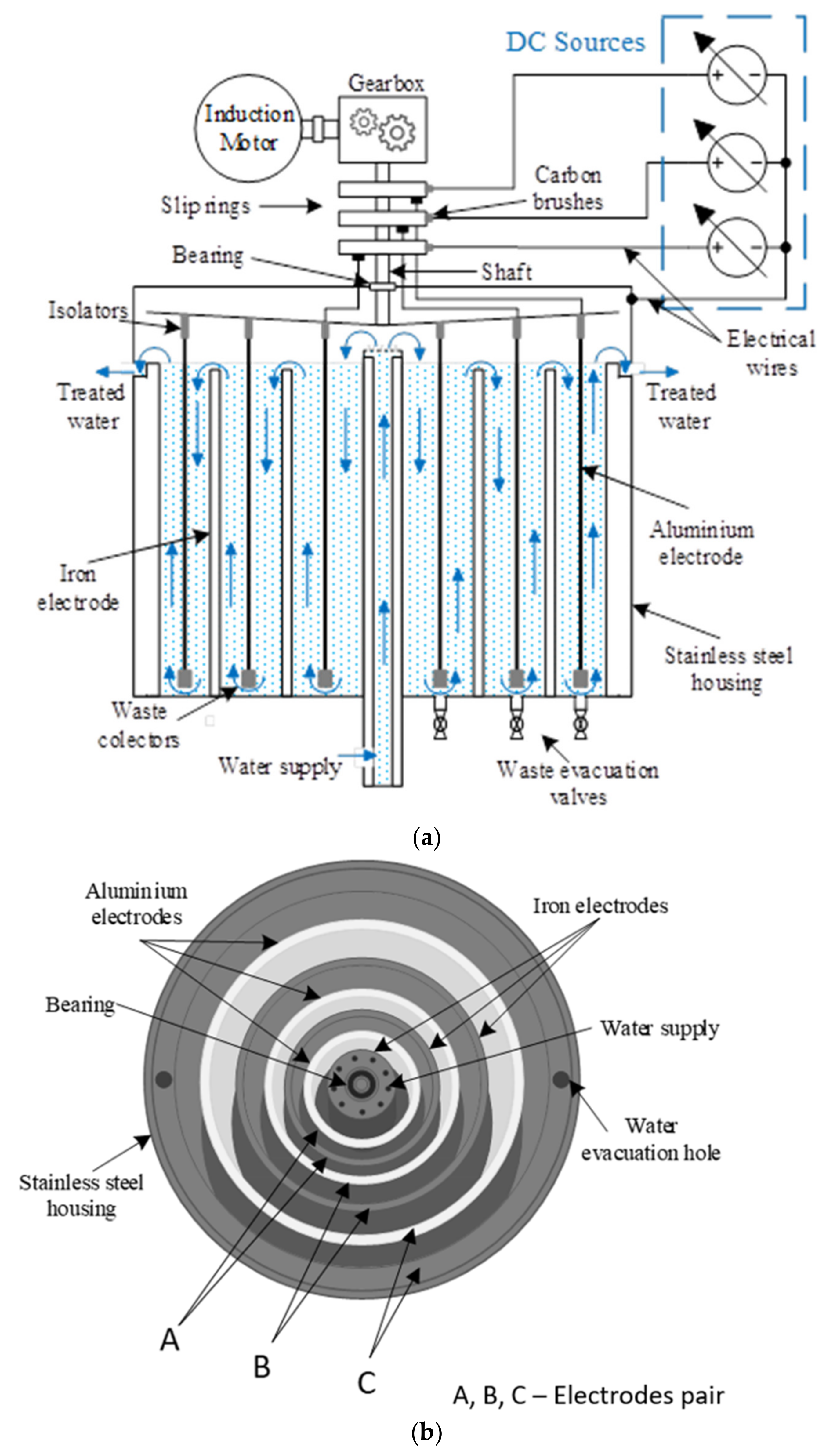
A pilot plant-scale continuous and flexible reactor was built for a flow rate ranging from 40 L∙h−1 to 200 L∙h−1. The EFC configuration shown in Figure 1 consisted of three pairs of concentric cylindrical electrodes (A, B, C), with each pair of aluminum and iron as an anode and cathode, respectively, or vice versa, depending on the polarization. Each anode and cathode pair is separately connected to a programmable DC source, and three programmable DC sources assured the electrical charge throughout the whole EFC reactor. The EFC reactor is controlled and supervised through an automation system based on a PLC (programmable logic controller) and SCADA (supervisory control and data acquisition), presented in detail in previous reported work [22].
Depending on the connection to the DC source, several cell configurations can be set-up, with one cell, two cells, and three cells connected in series. For example, if only a pair of electrodes are connected to a DC source and the other pairs of electrodes are not connected, one electrochemical cell works. If two pairs of the electrodes are connected separately to the respective DC sources and one pair of the electrodes is not connected to its DC source, two series of electrochemical cells operate. When the three pairs of electrodes are separately connected to each of the three DC sources, the three electrochemical cells operate. The reactor geometry considers all stages of conventional coagulation, i.e., dosing, mixing, and settling. The electrochemical cell assures the metal dosing through electrochemical processes and metal ion reaction, which further continues into the space of the unconnected electrodes where mixing continues by water flowing at a decreasing rate when settling occurs. All variants of the electrochemical cell are presented in Table 2, and the Sel/V ratio and placement of the cell within the reactor for each configuration is shown.
2.3. Analytical Methods
For the determination of the specific energy consumption, Wsp, relation (1) was applied:
where U is the potential (V), I is the applied current (A), t is the electrolysis time (h), and V is the volume of the treated solution (dm3) [23].
Wsp = U × I × t × 1000/V (Wh·m−3)
The specific ultraviolet absorbance (SUVA) parameter, defined as UV absorbance recorded at 254 nm (m−1) per unit of DOC (mg∙L−1), was also used to characterize the NOM hydrophobic or hydrophilic characteristics and implications to predict the coagulation efficiency [24]. SUVA describes the aromatic character of the dissolved organic matter in a water sample and is calculated according to Equation (2):
SUVA = A254 × 100/DOC (L·m−1·mg−1)
The total organic carbon (TOC) parameter was determined using a Shimadzu TOC analyzer, which was also used to determine the dissolved organic carbon (DOC) parameter under similar conditions after filtering through a 0.45 µm PVDF membrane. A254 was determined using a Varian Cary 100 spectrophotometer (Agilent Technologies, Santa Clara, CA, USA).
Aluminum concentration was determined using Varian 110 Atomic Absorption Spectroscopy (AAS). Turbidity was measured with a Hach turbidimeter and a Hach portable multimeter was used for conductivity and pH measurements. Sulfate, chloride, and hardness were determined in accordance with standardized methods [25].
The charge loading rates (Q) were determined by Equation (3) and were used to describe the rate of coagulant generation [26]:
where I is current (A) and F is flow rate (L∙h−1).
Q = I/F (C∙L−1)
3. Results
3.1. Optimization of EFC Reactor Operation Using Al Anode
The net volume of the EC reactor (V) is 21.19 L and the total volume of the electrode (Vel) is 3.79 L (ABC) and the total active area of the electrodes (Sel) is related to the electrode pair connection as it is presented in Table 2.
A very important parameter in coagulation is the aluminum ion dosage that is directly linked to the current value. To check the effect of the placement of the anode, the measured experimental value was compared with the calculated theoretical (wt) value based on Faraday’s law (4):
where n represents the number the electrons transferred in the anodic reaction (3), F is Faraday’s constant (96,486 C∙mol−1), M is the aluminum atomic weight (27), and t is the treatment time in seconds.
The theoretical value (wt) is considered in the stage of setting up the operational conditions related to the current density for the galvanostatic regime. However, the experimentally determined aluminum value (we), which represents the concentration of aluminum dosed in situ during the electrolysis time, is different compared to the theoretical value and can also be determined by a modified Faraday’s law (5) [27]:
where Φ is a correction factor depending on the current efficiency or faradaic yield, determined by the difference between the theoretical and practical dissolution of sacrificial anodes. The Φ value of 1 corresponds to the theoretical value, and the lower value informed by the parallel reaction occurring as well as the anode dissolution and a value higher than 1 shows a simultaneous chemical and electrochemical mechanism for metal dose generation that is frequent for aluminum. The reactor operation was monitored for one cell and three series cells and the results are presented in Table 3 at different current density.
It was noticed that the placement of the electrolysis cell within the reactor influenced the aluminum dissolution. The practical dissolution of aluminum was lower than the theoretical one for the lowest distance between the aluminum electrode and the reactor walls and the lowest Sel/V ratio. For the other arrangements, the practical aluminum weight was higher than the theoretical one, which is a common mechanism involving the electrochemical process coupled with the chemical process for aluminum dissolution. This also occurred for all coupled electrodes.
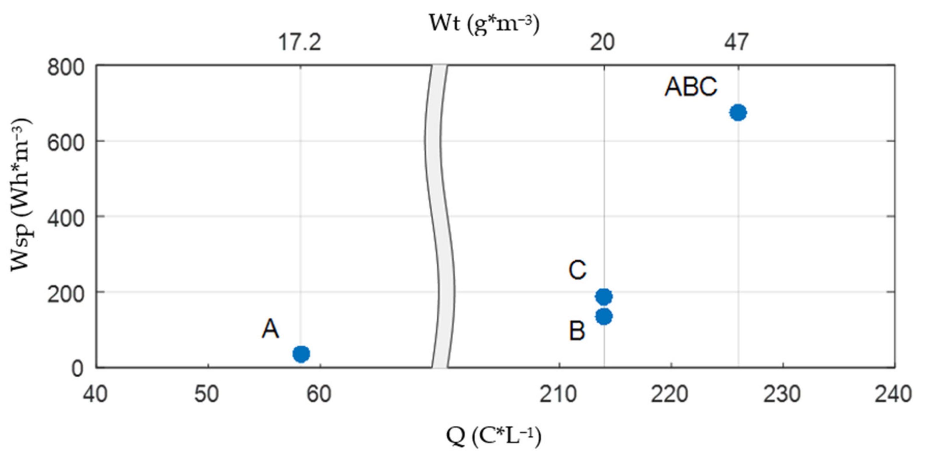
A very important indicator for EC is energy consumption, which depends on the current density, reactor configuration, and electrode geometry. For the same current density, the energy consumption was determined for each one and for the three cell configurations, and the results are presented in Figure 2, also considering the theoretical aluminum dose. For one cell configuration, the aluminum dose at the same current density is almost similar, e.g., 17 and 20 g∙m−3; respectively, but the energy consumption varied from 33 Wh∙m−3 for the A cell to 133 Wh∙m−3 for the B cell and 188 Wh∙m−3 for the C cell. Considering the three cell configurations, for about double the dose of aluminum (47 g∙m−3), a slightly higher charge loading rate at a much higher energy consumption rate (673 Wh∙m−3) was found. This behavior is associated with the electrode surface increase and implies a cell voltage (U) increase according to the Equation (6):
where EA and EC are the reversible anodic and cathodic potentials; ηA and are the corresponding overvoltages, respectively; and IR corresponds to the ohmic drop associated with the electrolyte resistivity (R). Based on the energy consumption indicator linked to the similar aluminum dose at the same current density, the A cell configuration was chosen for further experiments related to the reactor operational optimization and testing for specific drinking water treatment applications.
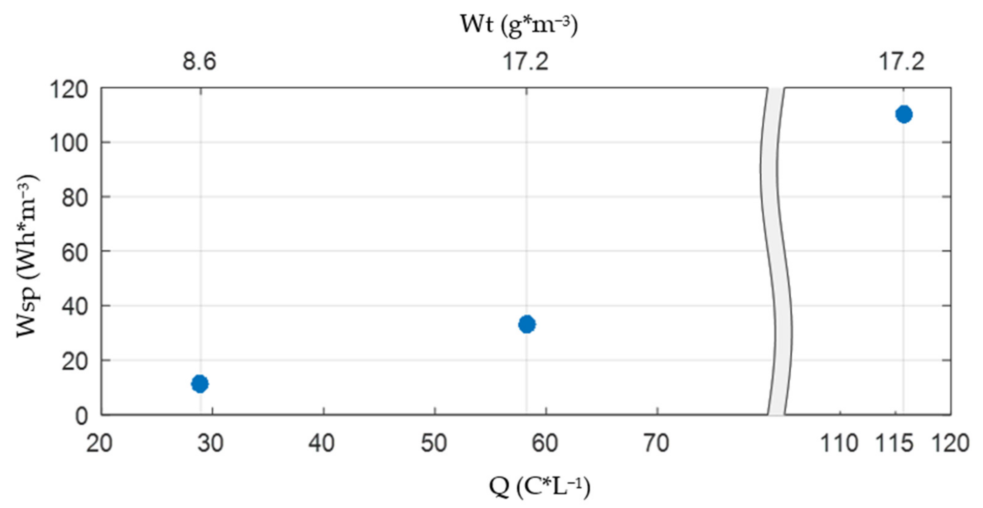
The current density effect on the energy consumption was tested for the A cell configuration by applying 2.5, 5, and 10 A∙m−2 current densities and the results are presented in Figure 3. The charge loading rate proportionally and directly increased with the current density. By doubling the current density, the charge loading rate increased twice and the energy consumption increased three times due to the progressive increase in U, maintaining the electrolysis time. It is obviously that the current density can be set to achieve the aluminum dose that is required for specific water treatment applications.
Furthermore, the effect of the flow rate on the energy consumption and aluminum dose was studied, considering the flow rate of 40 and 120 L∙h−1, respectively, for the same current density (Figure 4). In fact, the effect of charge loading rates described by Equation (3) and considered as the rate of the coagulant generation was assessed.
There is a reverse proportionality between the flow rate and the charge loading rates, and the energy consumption. In addition to the coagulant dose requirement, the flow rate should be set to assure the flocculation process, which depends on the raw water characteristics as well as the hydraulic conditions.
3.2. Reactor Testing in Real Surface Water Treatment for Drinking Purpose
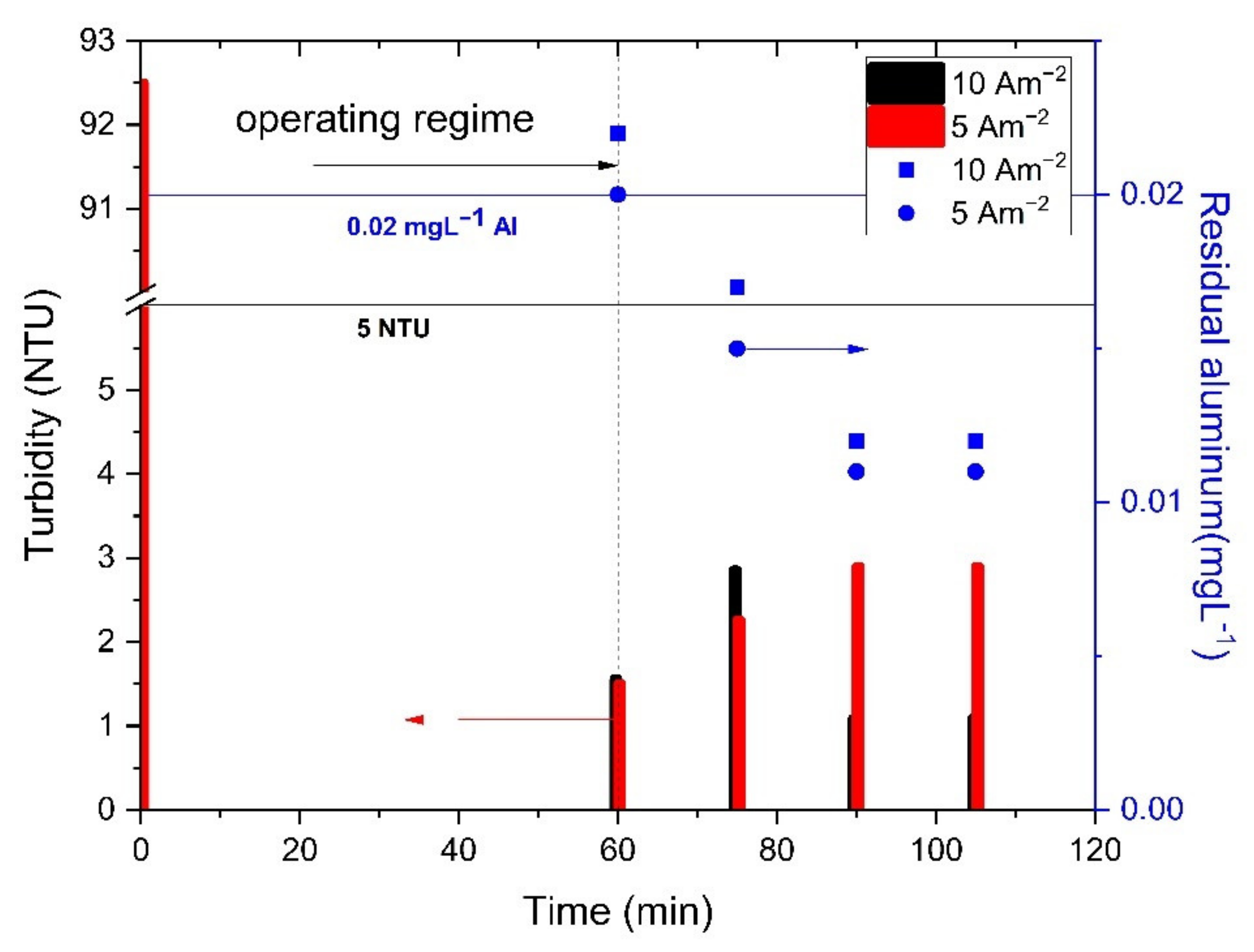
Considering all of the abovementioned operation conditions for the reactor using an aluminum anode, the A cell configuration at 40 L∙h−1 flow under 5 and 10 Am−2 was applied in testing real surface water collected from Bega River, Timisoara city, Romania, under flood conditions, characterized by a high turbidity of 93 NTU and a high content of natural organic matters that is manly dissolved (DOC of 8.3 mg C∙L−1 vs. TOC of 9.0 mg C∙L−1; see Table 1). The results regarding the time evolution of turbidity and residual aluminum are presented in Figure 5.
Under these operating conditions, starting with the operating regime, the turbidity was below 5 NTU, as the required limit for the drinking water for both applied current densities, but the lowest values were reached for 10 A∙m−2. Except for the first value, residual aluminum was also below the imposed limit of 0.02 mg∙L−1. The dissolved organic carbon (DOC) parameter was considered for the assessment considering its main impact on the disinfection stage of drinking water, generating harmful disinfection by-products. For the current density of 5 A∙m−2, a slight reduction of DOC was achieved (about 10%), while for the current density of 10 A∙m−2, the DOC reduction was about 60%, which is in accordance with data in the literature regarding enhanced coagulation [28] versus conventional coagulation [29]. Under these conditions, by applying the current density of 10 A∙m−2, the enhanced electrocoagulation occurred and a higher reduction of natural organic matter (NOM) was achieved in comparison with conventional electrocoagulation at 5 A∙m−2. An initial SUVA value of 3.9 L∙m−1∙mg−1 of raw water suggests high concentrations of NOM containing high molecular weight (MW) hydrophobic dissolved carbon, characterized by a high charge density that can be easily removed by coagulation [26,30] and electrocoagulation [31,32]. This removal can occur by aluminum species that are generated based on aluminum anode dissolution and aluminum ion hydrolysis, based on the following reactions (7)–(10):
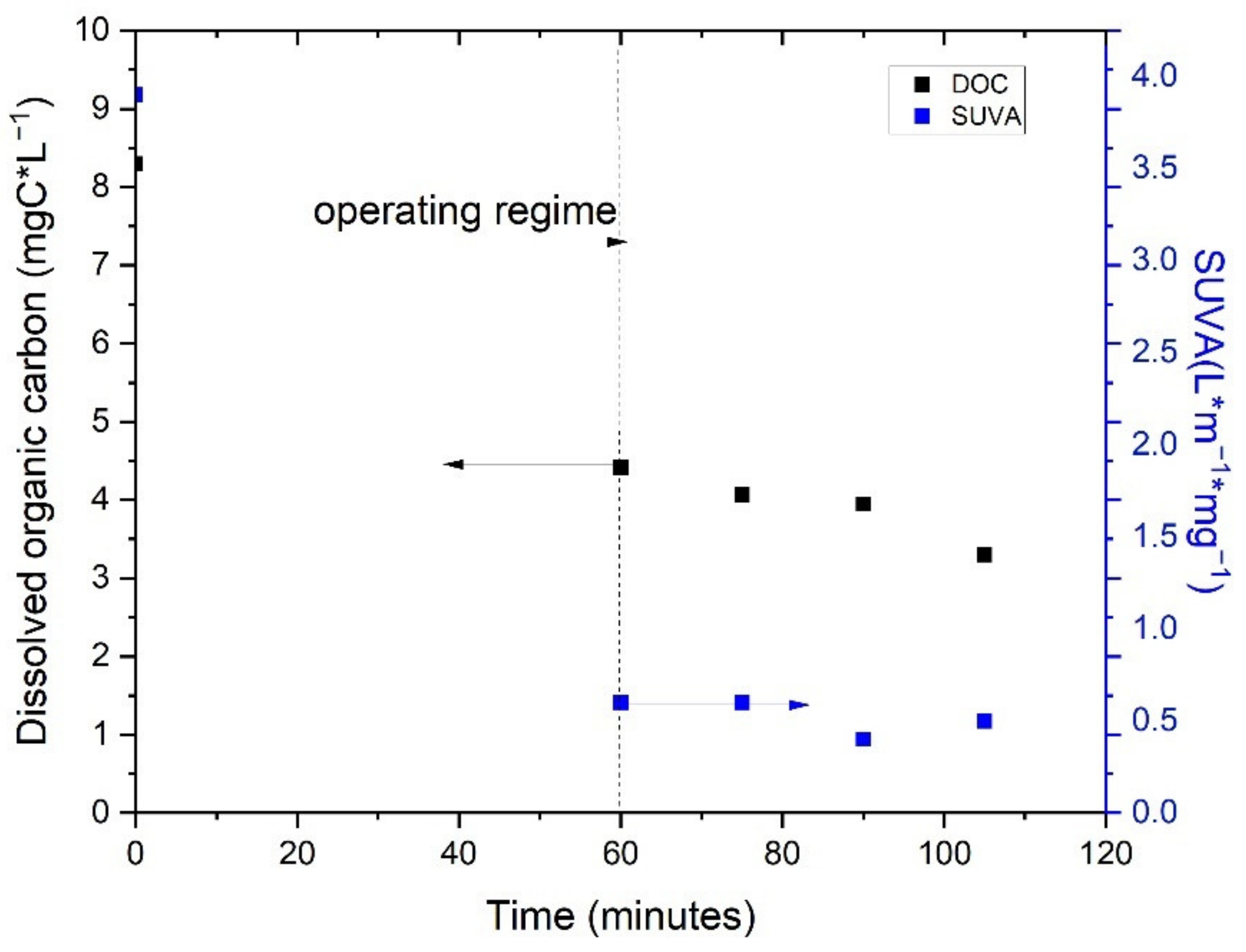
Figure 6 presents the time evolution of the dissolved organic carbon and SUVA parameters by applying the current density of 10 A∙m−2.
During electrocoagulation operation at 10 A∙m−2, both DOC and SUVA were greatly reduced. Lower SUVA values correspond to a greater reduction in high MW NOM and A254 was more predominantly reduced (about 94.6%) compared to DOC (about 60%).
4. Discussion
The results regarding the functionality of the flexible and continuous electroflotocoagulation reactor, based on three pairs of concentric cylindrical aluminum and iron electrodes, show that it is possible to build several variants of the EFC-reactor-integrated electrocoagulation cells, which assure different points of coagulant dosing, mixing, reaction, and electroflotation and/or settling times. A, B, C, and ABC cell configurations tested for in situ generation of the aluminum coagulant showed that the practical dissolution of aluminum was higher for all types of cell arrangements and positions, except the one at the lowest distance between the aluminum electrode and the reactor walls and at the lowest Sel/V ratio (C cell). The placement of the electroflotocoagulation cells has a significant influence on the energy consumption; the A cell configuration is the most energy-efficient and the ABC cell configuration is the most energy-consuming.
There is a direct proportionality between the current density and the energy consumption, and a reverse proportionality between the flow rate and the charge loading rates and energy consumption.
The A cell configuration, tested at current densities of 5 and 10 A∙m−2 for the treatment of surface water (Bega river, Timisoara city, Romania) rich in hydrophobic NOM (8.3 mg C∙L−1 and SUVA parameter of 3.9 L∙m−1∙mg−1) and with a high turbidity of 92 NTU under flood conditions, showed the best results at 10 A∙m−2 through enhanced electroflotocoagulation, confirming the excessive dose of aluminum coagulant required for NOM removal. The effect of the electrode position that determines the reactor configuration on the specific energy and electrode consumption allowed the selection of the A cell, characterized by Sel of 0.392 m2 75.38 m2/m3 (Sel/V) and placement coordinates of a 69 mm internal diameter and 70.5 mm external diameter, as the most energy efficient reactor configuration. Moreover, the specific energy consumption was increased by a higher current density that improves the coagulant dosing rate and lower flow rate, which should assure the flocculation stage.
Based on the results presented above, depending on the raw water or wastewater characteristics, further operating an EFC reactor considers the following aspects:
Selecting aluminum and/or iron anodes depending on raw water characteristics (the presence of arsenic necessitates selection of an iron anode, based on our previous reported work [4]);
Dosing point function of the water composition homogeneity and suspension characteristics (e.g., an A cell for homogeneous composition and colloidal systems);
Mixing, reaction, and floc forming through the charge loading rate (current density and flow rate) to be sufficient for floc forming but not too high due to the floc destruction risk.
Further studies will be focused on optimizing the operating conditions for different real situations related to raw water characteristics for drinking purposes in rural areas. In addition, specific configurations will be tested for different wastewaters or industrial effluents characterized by high content of suspension matter and organic loading.
5. Conclusions
In a pilot plant-scale study, a new flexible and continuous electroflotocoagulation reactor was built, based on concentric cylindrical electrodes, which can be operated to in situ generate aluminum or iron ions depending on the DC connection. The reactor was operationally investigated and tested for the treatment of surface water (Bega river, Timisoara city, Romania) rich in hydrophobic NOM (8.3 mg C∙L−1 and SUVA parameter of 3.9 L∙m−1∙mg−1) and with a high turbidity of 92 NTU under flood conditions. The effect of the electrode position that determines the reactor configuration based on the specific energy and electrode consumption allowed the selection of the A cell, characterized by 75.38 m2/m3 (Sel/V), as the most energy efficient reactor configuration. Additionally, the specific energy consumption was increased by a higher current density that improves the coagulant dosing rate and lower flow rate, which should assure the flocculation stage.
The most energy efficient A cell configuration using an aluminum anode and iron cathode was tested successfully at current densities of 5 and 10 A∙m−2 for the treatment of surface water (Bega river, Timisoara city, Romania) rich in hydrophobic NOM (8.3 mg C∙L−1 and SUVA parameter of 3.9 L∙m−1∙mg−1) and with a high turbidity of 92 NTU under flood conditions for drinking purposes. The best results that assured 97% turbidity removal, 87% for A254, and 60% for DOC removal were achieved for an operational current density of 10 A∙m−2 to allow higher doses of aluminum that are required by the enhanced coagulation approach, with specific energy and electrode consumption of 0.1 kWh∙m−3 and 0.017 kg Al∙m−3, respectively. The results of this study show the great potential and versatility of this new and flexible electroflotocoagulation reactor to be operated at minimum energy and electrode consumption levels for the treatment of various water matrices on an industrial scale.
Author Contributions
Conceptualization, F.M. and C.-A.T.; methodology, F.M. and C.-A.T.; investigation, S.V. and L.-D.V.; resources, C.-A.T., F.M. and L.-D.V.; writing—original draft preparation, S.V., L.-D.V. and F.M.; writing—review and editing, F.M. All authors have read and agreed to the published version of the manuscript.
Funding
This research received no external funding.
Acknowledgments
This work was supported partially by a grant from the Romanian Ministry of Education and Research, CNCS—UEFISCDI, project code PN-III-P2-2.1-PED-2019-4492, contract number 441PED/2020 (3DSAPECYT) and partially by a grant of the Romanian Ministry of Research, Innovation and Digitalization, project number PFE 26/30.12.2021, PERFORM-CDI@UPT100 within Program 1—Development of the national system of Research and Development, Subprogram 1.2—Institutional Performance—Institutional Development Projects—Excellence Funding Projects in RDI, PNCDI III.
Conflicts of Interest
The authors declare no conflict of interest.
References
- Kim, T.H.; Park, C.; Shin, E.B.; Kim, S. Decolorization of disperse and reactive dyes by continuous electrocoagulation process. Desalination 2002, 150, 165–175. [Google Scholar] [CrossRef]
- AlJaberi, F.Y.; Alardhi, S.M.; Ahmed, S.A.; Salman, A.D.; Juzsakova, T.; Cretescu, I.; Le, P.C.; Chung, W.J.; Chang, S.W.; Nguyeng, D.D. Can electrocoagulation technology be integrated with wastewater treatment systems to improve treatment efficiency? Environ. Res. 2022, 214, 113890. [Google Scholar] [CrossRef] [PubMed]
- Vázquez, A.; Rodríguez, I.; Lázaro, I. Primary potential and current density distribution analysis: A first approach for designing electrocoagulation reactors. Chem. Eng. J. 2012, 179, 253–261. [Google Scholar] [CrossRef]
- Pop, A.; Baciu, A.; Wanko, G.; Bodor, K.; Vlaicu, I.; Manea, F. Assessment of electrocoagulation process. Application in arsenic removal from drinking water. Environ. Eng. Manag. J. 2017, 16, 821–828. [Google Scholar]
- Baciu, A.; Pop, A.; Bodor, K.; Vlaicu, I. Assessment of electrocoagulation process for drinking water treatment. Environ. Eng. Manag. J. 2015, 14, 1347–1354. [Google Scholar]
- Golder, A.K.; Samanta, A.N.; Ray, S. Removal of Cr3+ by electrocoagulation with multiple electrodes: Bipolar and monopolar configurations. J. Hazard. Mater. 2007, 141, 653–661. [Google Scholar] [CrossRef]
- Alkhatib, A.M.; Hawari, A.H.; Hafiz, M.A.; Benamor, A. A novel cylindrical electrode configuration for inducing dielectrophoretic forces during electrocoagulation. J. Water Process. Eng. 2020, 35, 101195. [Google Scholar] [CrossRef]
- Naje, A.S.; Chelliapan, S.; Zakaria, Z.; Ajeel, M.A.; Alaba, P.A. A review of electrocoagulation technology for the treatment of textile wastewater. Rev. Chem. Eng. 2016, 33, 263–292. [Google Scholar] [CrossRef]
- Cruz, K.D.; Mateo, N.M.; Tangara, N.P.; Almendrala, M.C. Reactor design optimization on the electrocoagulation treatment of sugarcane molasses-based distillery wastewater. IOP Conf. Ser. Earth Environ. Sci. 2019, 344, 012023. [Google Scholar] [CrossRef]
- Mameri, N.; Yeddou, A.R.; Lounici, H.; Belhocine, D.; Grib, H.; Bariou, B. Defluoridation of septentrional Sahara water of North Africa by electrocoagulation process using bipolar aluminium electrodes. Water Res. 1998, 32, 1604–1612. [Google Scholar] [CrossRef]
- Khaled, B.; Wided, B.; Béchir, H.; Limam, A.; Mouna, L.; Tlili, Z. Investigation of electrocoagulation reactor design parameters effect on the removal of cadmium from synthetic and phosphate industrial wastewater. Arab. J. Chem. 2019, 12, 1848–1859. [Google Scholar] [CrossRef]
- Wided, B.; Khaled, B.; Elimame, E.; Mouna, L.; Béchir, H. Optimization of electrocoagulation operating parameters and reactor design for zinc removal: Application to industrial Tunisian wastewater. Desalin. Water Treat. 2015, 56, 2706–2714. [Google Scholar] [CrossRef]
- Holt, P.K.; Barton, G.W.; Mitchell, C.A. The future for electrocoagulation as a localised water treatment technology. Chemosphere 2005, 59, 355–367. [Google Scholar] [CrossRef] [PubMed]
- Sharma, G.; Choi, J.; Shon, H.K.; Phuntsho, S. Solar-powered electrocoagulation system for water and wastewater treatment. Desalin. Water Treat. 2011, 32, 381–388. [Google Scholar] [CrossRef]
- Holt, P.K.; Barton, G.W.; Wark, M.; Mitchell, C.A. A quantitative comparison between chemical dosing and electrocoagulation. Colloids Surf. A Physicochem. Eng. Asp. 2002, 211, 233–248. [Google Scholar] [CrossRef]
- Butler, E.; Hung, Y.-T.; Yeh, R.Y.-L.; Suleiman Al Ahmad, M. Electrocoagulation in Wastewater Treatment. Water 2011, 3, 495–525. [Google Scholar] [CrossRef]
- Sun, Y.; Zhou, S.; Chiang, P.; Shah, K.J. Evaluation and optimization of enhanced coagulation process: Water and energy nexus. Water-Energy Nexus 2019, 2, 25–36. [Google Scholar] [CrossRef]
- Chaudhari, S.; Kumar, P.R.; Khilar, K.C.; Mahajan, S.P. Removal of arsenic from water by electrocoagulation. Chemosphere 2004, 55, 1245–1252. [Google Scholar] [CrossRef]
- Hansen, H.K.; Nunez, P.; Grandon, R. Electrocoagulation as a remediation tool for wastewaters containing arsenic. Miner. Eng. 2006, 19, 521–524. [Google Scholar] [CrossRef]
- Maldonado-Reyes, A.; Montero-Ocampo, C.; Solorza-Feria, O. Remediation of drinking water contaminated with arsenic by electro-removal process using different metal electrodes. J. Environ. Monit. 2007, 9, 1241–1247. [Google Scholar] [CrossRef]
- Ayedi, H.; Mouedhen, G.; Feki, M.; Petris, M. Behavior of aluminium electrodes in electrocoagulation process. J. Hazard. Mater. 2008, 150, 124–135. [Google Scholar] [CrossRef]
- Hedes, A.; Vitan, D.; Tudoran, C.A.; Muntean, O. Experimental Research on Electrocoagulation for Wastewater Treatment. In Proceedings of the 20th International Symposium on Power Electronics (Ee), Novi Sad, Serbia, 23–26 October 2019. [Google Scholar]
- Vlaicu, I.; Pop, A.; Manea, F.; Radovan, C. Degradation of humic acid from water by advanced electrochemical oxidation method. Water Sci. Technol.:Water Supply 2011, 11, 85–95. [Google Scholar] [CrossRef] [Green Version]
- Edzwald, J.K. Coagulation in drinking water treatment: Particles, organics and coagulants. Water Sci. Technol. 1993, 27, 21–35. [Google Scholar] [CrossRef]
- Eaton, A.D.; Clesceri, L.S.; Rice, E.W.; Greenberg, A.E. Standard Methods for the Examination of Water and Wastewater, 21st ed.; APHA-AWWA-WEF: Washington, DC, USA, 2005. [Google Scholar]
- Dubrawski, K.L.; Mohseni, M. Standardizing electrocoagulation reactor design: Iron electrodes for NOM removal. Chemosphere 2013, 91, 55–60. [Google Scholar] [CrossRef]
- Hakizimana, J.N.; Gourich, B.; Chafi, M.; Stiriba, Y.; Vial, C.; Drogui, P.; Naja, J. Electrocoagulation process in water treatment: A review of electrocoagulation modeling approaches. Desalination 2017, 404, 1–21. [Google Scholar] [CrossRef]
- Sillanpää, M.; Ncibi, M.C.; Matilainen, A.; Vepsäläinen, M. Removal of natural organic matter in drinking water treatment by coagulation: A comprehensive review. Chemosphere 2018, 190, 54–71. [Google Scholar] [CrossRef]
- Matilainen, A.; Vepsäläinen, M.; Sillanpää, M. Natural organic matter removal by coagulation during drinking water treatment: A review. Adv. Colloid Interface Sci. 2010, 159, 189–197. [Google Scholar] [CrossRef]
- Edzwald, J.K. Coagulation Concepts for Removal of TOC; AWWA WQTC: San Francisco, CA, USA, 1994. [Google Scholar]
- Dubrawski, K.L. Reactor Design Parameters, In-Situ Speciation Identification, and Potential Balance Modeling for Natural Organic Matter Removal by Electrocoagulation. Ph.D. Thesis, University of British Columbia, Vancouver, BC, Canada, 2013. [Google Scholar]
- Mollah, M.Y.; Schennach, R.; Parga, J.R.; Cocke, D.L. Electrocoagulation (EC)—Science and applications. J. Hazard. Mater. 2001, 84, 29–41. [Google Scholar] [CrossRef]
Figure 1.
EFC reactor configuration: (a) cross-section view; (b) top-view.

Figure 2.
Effect of cell configuration on energy consumption at the same current density of 5 Am−2 and corresponding theoretical aluminum dose (g∙m−3) and charge loading rate (C∙L−1) at F = 40 L∙h−1.
Figure 2.
Effect of cell configuration on energy consumption at the same current density of 5 Am−2 and corresponding theoretical aluminum dose (g∙m−3) and charge loading rate (C∙L−1) at F = 40 L∙h−1.

Figure 3.
Effect of current density on the energy consumption and corresponding theoretical aluminum dose (g∙m−3) and charge loading rate (C∙L−1) in A cell configuration at F = 40 L∙h −1.
Figure 3.
Effect of current density on the energy consumption and corresponding theoretical aluminum dose (g∙m−3) and charge loading rate (C∙L−1) in A cell configuration at F = 40 L∙h −1.

Figure 4.
Effect of flow rate on the energy consumption and corresponding theoretical aluminum dose (g∙m−3) and charge loading rate (C∙L−1) in A cell configuration; current density of 5 A∙m−2.
Figure 4.
Effect of flow rate on the energy consumption and corresponding theoretical aluminum dose (g∙m−3) and charge loading rate (C∙L−1) in A cell configuration; current density of 5 A∙m−2.

Figure 5.
Time evolution of turbidity and residual aluminum concentration during electrochemical reactor operation in A cell configuration; current density of 10 Am−2 and 5 Am−2; initial turbidity of 92.5 NTU; F = 40 L∙h−1.
Figure 5.
Time evolution of turbidity and residual aluminum concentration during electrochemical reactor operation in A cell configuration; current density of 10 Am−2 and 5 Am−2; initial turbidity of 92.5 NTU; F = 40 L∙h−1.

Figure 6.
Time evolution of dissolved organic carbon and SUVA parameters during electrochemical reactor operation in A cell configuration; current density of 10 A∙m−2; initial turbidity of 92.5 NTU; DOC of 8.3 mg C∙L−1; F = 40 L∙h−1.
Figure 6.
Time evolution of dissolved organic carbon and SUVA parameters during electrochemical reactor operation in A cell configuration; current density of 10 A∙m−2; initial turbidity of 92.5 NTU; DOC of 8.3 mg C∙L−1; F = 40 L∙h−1.


Table 1.
Surface water characteristics.
| Characteristics | Value |
|---|---|
| pH | 8.1 |
| Turbidity | 92 NTU |
| Total Organic Carbon | 9.0 mg C∙L−1 |
| Dissolved Organic Carbon | 8.3 mg C∙L−1 |
| Conductivity | 750 µS∙cm−1 |
| Hardness | 45 mg CaO∙L−1 |
| Sulphate | 20 mg∙L−1 |
| Chloride | 6.6 mg∙L−1 |
| Absorbance recorded at 254 nm (A254) | 0.3495 cm−1 |
| Specific UV absorbance (SUVA) | 3.9 L∙m−1∙mg−1 |
| Aluminum | 5 µg∙L−1 |
Table 2.
Number and type of electrochemical cell function of the electrodes connected to DC source.
| Electrodes Pair | Electrochemical Series Cells | Vel, m3 | Sel, m2 | Sel/V, m2·m−3 | Placement of Cell | ||||
|---|---|---|---|---|---|---|---|---|---|
| A | B | C | One Cell/Name | Two Cells/Name | Three Cells/Name | ||||
| x | - | - | x/A | - | - | 0.00520 | 0.392 | 75.40 | Din = 69 mm Dout = 70.5 mm |
| - | x | - | x/B | - | - | 0.00687 | 0.573 | 83.40 | Din = 98 mm Dout = 41.5 mm |
| - | - | x | x/C | - | - | 0.00912 | 0.753 | 82.60 | Din = 127 mm Dout = 12.5 mm |
| x | x | - | - | x/AB | - | 0.01207 | 0.965 | 79.95 | Din = 69 mm Dout = 70.5 mm |
| x | - | x | - | x/AC | - | 0.01432 | 1.145 | 79.95 | Din = 69 mm Dout = 12.5 mm |
| - | x | x | - | x/BC | - | 0.01599 | 1.326 | 82.90 | Din = 98 mm Dout = 12.5 mm |
| x | x | x | - | - | x/ABC | 0.02119 | 1.718 | 81.07 | Din = 69 mm Dout = 12.5 mm |
Note: x—connected, -—not connected, Din—internal diameter, Dout—external diameter.
Table 3.
Comparison of the calculated theoretical metal dissolution value (wt) with the respect to the experimental value (we) for F = 40 L∙h−1.
Table 3.
Comparison of the calculated theoretical metal dissolution value (wt) with the respect to the experimental value (we) for F = 40 L∙h−1.
| Electrodes Pair | Electrochemical Series Cells | i, A/m2 | wt *, g/m3 | we **, g/m3 | Φ | ||||
|---|---|---|---|---|---|---|---|---|---|
| A | B | C | One Cell/Name | Two Cells/Name | Three Cells/Name | ||||
| x | - | - | x/A | - | - | 2.5 | 8.6 | 9.8 | 1.14 |
| 5 | 17.2 | 20.9 | 1.21 | ||||||
| 10 | 34.4 | 42.6 | 1.24 | ||||||
| - | x | - | x/B | - | - | 5 | 20.0 | 26.0 | 1.30 |
| 10 | 40.0 | 47.0 | 1.17 | ||||||
| - | - | x | x/C | - | - | 5 | 20.0 | 18.9 | 0.95 |
| 10 | 40.0 | 36.1 | 0.90 | ||||||
| x | x | x | - | - | x/ABC | 5 | 47 | 61.92 | 1.32 |
Note: * calculated by Faraday’s law, ** experimentally determined.
Publisher’s Note: MDPI stays neutral with regard to jurisdictional claims in published maps and institutional affiliations. |
© 2022 by the authors. Licensee MDPI, Basel, Switzerland. This article is an open access article distributed under the terms and conditions of the Creative Commons Attribution (CC BY) license (https://creativecommons.org/licenses/by/4.0/).
Share and Cite
MDPI and ACS Style
Vasilie, S.; Vitan, L.-D.; Tudoran, C.-A.; Manea, F. Flexible Electroflotocoagulation Reactor: New Design and Testing in Treatment of Real Surface Water. Water 2022, 14, 2990. https://doi.org/10.3390/w14192990
AMA Style
Vasilie S, Vitan L-D, Tudoran C-A, Manea F. Flexible Electroflotocoagulation Reactor: New Design and Testing in Treatment of Real Surface Water. Water. 2022; 14(19):2990. https://doi.org/10.3390/w14192990
Chicago/Turabian StyleVasilie, Sergiu, Liviu-Danut Vitan, Constantin-Adrian Tudoran, and Florica Manea. 2022. "Flexible Electroflotocoagulation Reactor: New Design and Testing in Treatment of Real Surface Water" Water 14, no. 19: 2990. https://doi.org/10.3390/w14192990
Note that from the first issue of 2016, this journal uses article numbers instead of page numbers. See further details here.