
Effect of Animal Burrows on the Vulnerability of Levees to Concentrated Erosion


Department of Civil, Environmental and Architectural Engineering University of Padua, Via Ognissanti 39, 35129 Padova, Italy
*
Author to whom correspondence should be addressed.
Water 2022, 14(18), 2777; https://doi.org/10.3390/w14182777
Submission received: 9 August 2022
/
Revised: 25 August 2022
/
Accepted: 30 August 2022
/
Published: 6 September 2022
(This article belongs to the Section Hydraulics and Hydrodynamics)
Abstract
:Earth dams and levees often offer an attractive habitat for burrowing animals such as porcupines, nutria, badgers, etc. However, their activity may damage the earth structure, potentially leading to catastrophic failures. If the burrow system connects the waterside and the landside, water flows through the pipe and it can start concentrated erosion. This paper shows that the conditions to trigger concentrated erosion can be generated by a local instability mechanism of the landside slope in which the soil cover between the cavity and the surface is expulsed due to increasing water pressure. A simplified model based on the limit equilibrium method is proposed and compared with bi-dimensional and three-dimensional finite element analyses. This mechanism can better explain real failure cases. The results provide useful suggestions for the assessment of levee vulnerability to animal burrows and for the management of water retaining structures.
1. Introduction
Water-retaining structures such as dams and levees are vulnerable to damage from burrowing animals [1]. These structures often attract animals because they are vegetated, close to water, and far from disturbing human activities. Species that commonly damage earth embankments include aquatic species, such as crayfish and crabs, and terrestrial species, such as nutria, porcupine, muskrat, beaver, badger, and foxes, among others. They can excavate cavities from the waterside or from the landside, creating isolated burrows or interconnected systems of dens and tunnels with diameters ranging from a few centimeters to almost one meter and lengths that can reach several meters [2].
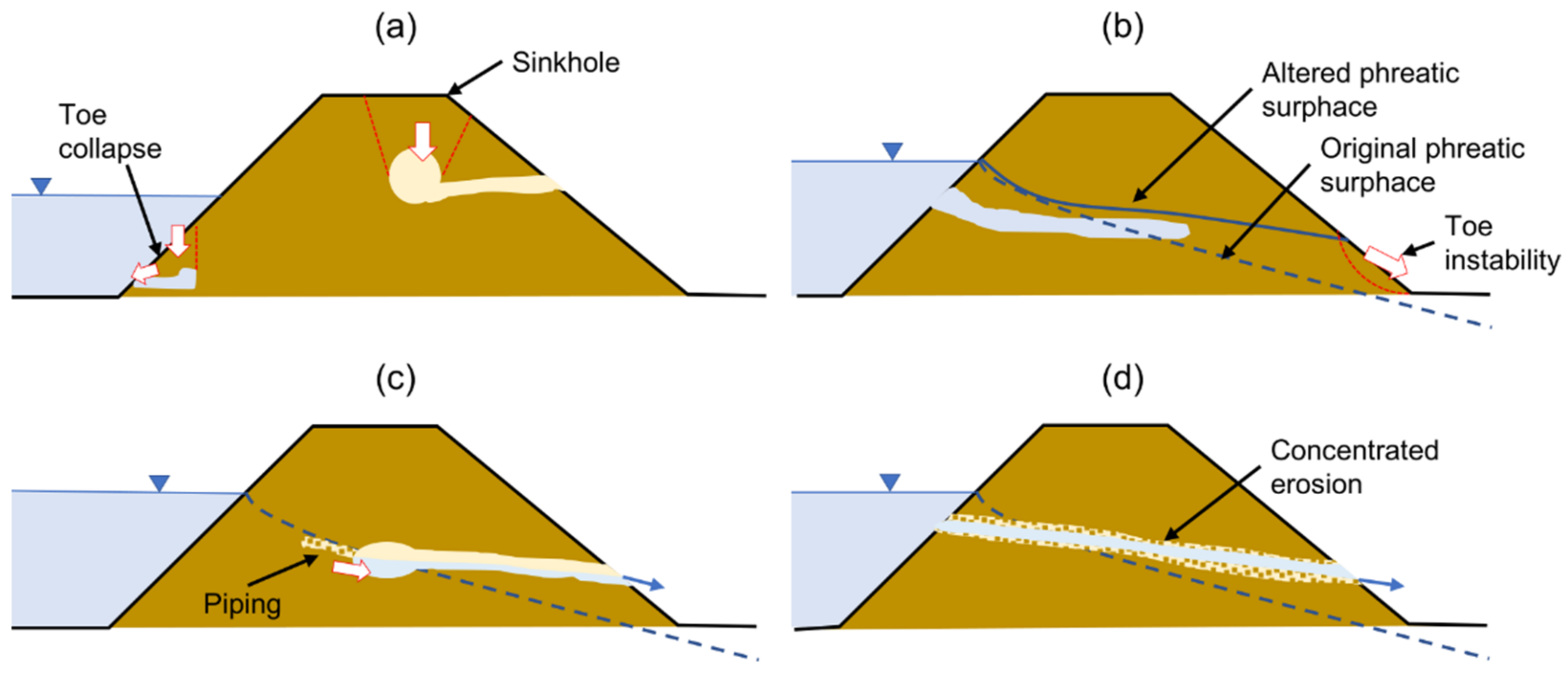
Animal intrusions alter both the strength and the hydraulic characteristic of earthen dams and levees. The presence of cavities weakens the structural integrity of the embankment, potentially causing localized collapses at the waterside toe, favoring erosion, or visible as sinkholes or surface depressions (Figure 1a). Cavity collapses near the crest can result in a loss of freeboard, thus endangering the dam during storm events; massive slope instability can result from collapsed burrows and soil losses. Hydraulic alteration includes modifications in the pore pressure distribution within the soil body (Figure 1b), thus decreasing the soil shear strength, and the initiation of internal erosion mechanisms such as backward erosion, piping (Figure 1c), and concentrated erosion (Figure 1d).
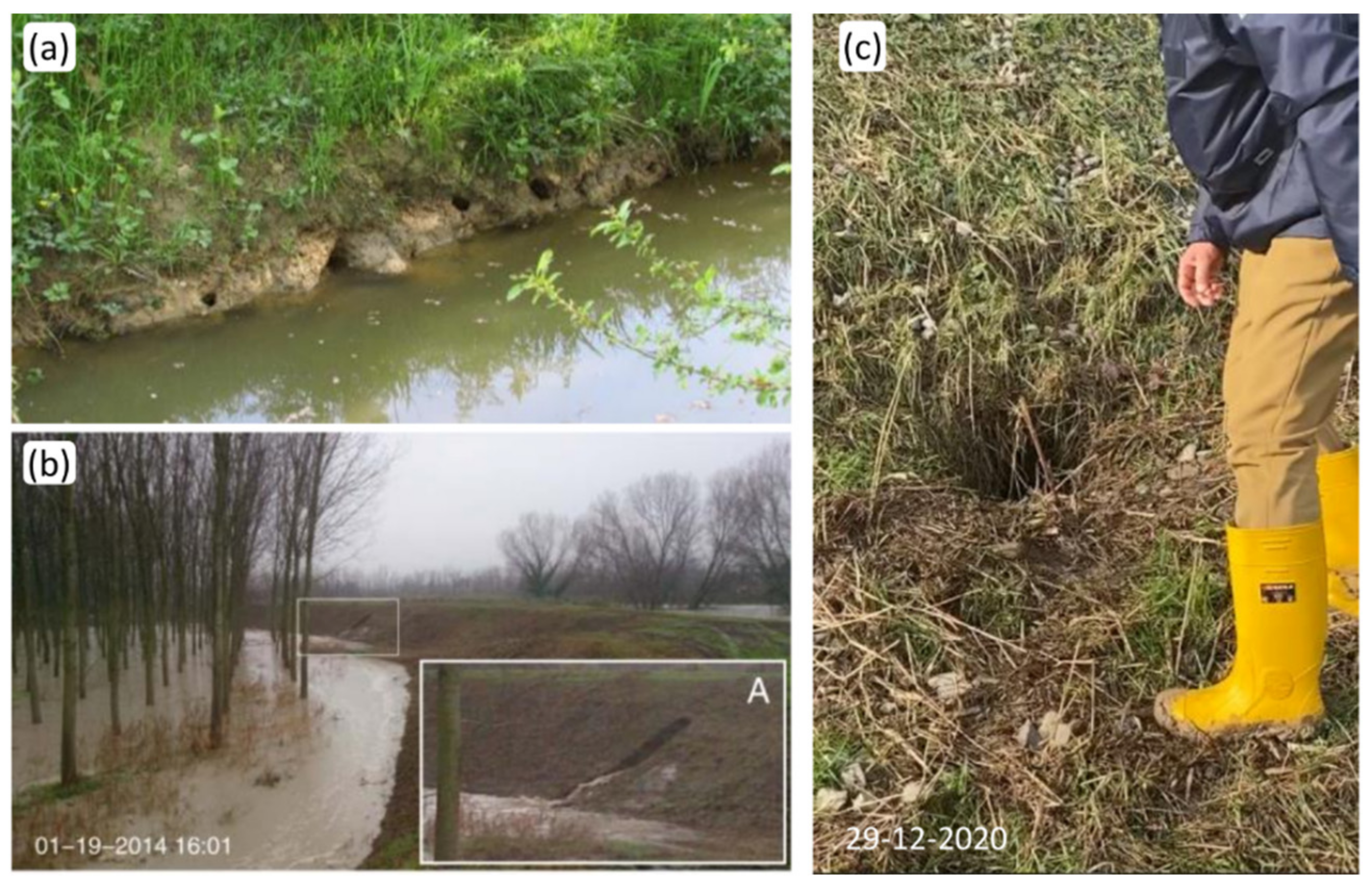
Figure 2 shows some examples of damaged levees by the activity of crayfish (Figure 2a) and burrowing mammals, probably porcupines or badgers (Figure 2b,c). Depending on the location, size, and number of animal burrows, the safety and functionality of earthen structures could be jeopardized. Meaningful overviews of the topic can be found in [2,3].
This paper focuses on the effect of small and medium-sized cavities, such as those burrowed by mammals, on the stability of the landside slope of levees. Recent studies investigated this issue numerically [5,6,7,8,9,10], conducting seepage analyses eventually coupled with the limit equilibrium method (LEM) to evaluate the factor of safety (FS) of the slope.
Bi-dimensional seepage analyses are performed considering idealized geometries and material properties of the cavity. In many cases, e.g., [6,8,10], failure is assumed to occur when the phreatic line reaches the landside. This is the necessary condition for the onset of erosion at the toe or through the levee body. With toe erosion, an initial micro instability can progress in a circular failure surface on the slope (Figure 1b), as observed experimentally by [11], and only some time later the opening of the breach may occur.
LEM stability analyses assume circular failure surfaces crossing the levee and the foundation subsoil and calculate FS with the previously calculated pore pressure distribution and considering the structural weakness due to the cavity [5,7,9,10]. The decrease in FS in the damaged levee is considered a proof of concept of the risk associated with the presence of cavities. However, for real cases, FS lower than one is obtained only with conservative assumptions [5,7].
If the burrow system connects the waterside and the landside, the water flowing through the pipe can start concentrated erosion [12]. The cavity expands at a rate that depends on the erodibility of the material, the length of the path, and the pressure difference between the entrance and exit [13], and can rapidly lead to the opening of the breach if no countermeasures are taken. This phenomenon is sometimes called (inappropriately) piping, but concentrated erosion occurs in a pre-existing cavity and it can be very fast, potentially leading to failure in a few hours [2,5,10,13,14]; in contrast, piping is the formation of a pipe as a consequence of retrogressive solid grain erosion due to seepage, usually progressing more slowly.
In this paper, an additional mechanism of local instability of the landside slope is introduced, which is capable of triggering concentrated erosion. We assume that a cavity, e.g., a den or a tunnel, is present near the landside slope and it is in hydraulic connection with the river, such that the water pressure increases with the water level. This pressure may induce a local failure of the soil cover between the cavity and the surface initiating the flow in the pipe, and concentrated erosion can rapidly open the breach. A simplified approach based on LEM is proposed to evaluate quantitatively the safety of the structure with respect to this mechanism (Section 2). The results are compared with more advanced bi-dimensional (2D) and three-dimensional (3D) numerical analyses with the finite element method (FEM) (Section 3 and Section 4). In contrast to other studies that considered seepage as the main cause of failure, here, the change in interstitial pore pressure is neglected, which is realistic in the case of rapid increase in water levels and low-permeability soils.
2. Simplified 2D Mechanism for the Stability of the Landside Slope near a Cavity
This section presents a local failure mechanism of the landside slope due to the increasing pressure inside a cavity; this local failure can induce concentrated erosion, rapidly causing a catastrophic failure of the structure. A simple 2D model of local stability of the soil wedge is proposed, applying a limit equilibrium approach. Although the real problem is complex and 3D, we believe that this method can provide insight into the key features of the phenomenon and represents an expedite way of evaluating the stability quantitatively. In this particular context, the soil is assumed to be a one-phase continuum material, and, therefore, seepage effects are not explicitly accounted for, in order to avoid additional complications and cumbersome assumptions on the hydromechanical behavior of unsaturated soils. The method is applicable in case of a rapid increase in water level and materials of low hydraulic conductivity, for which the saturation front propagates very slowly in the soil. These conditions are relatively frequent in river levees, even when made of silty sand, because in partially drained conditions, the hydraulic conductivity of these soils can reach very low values, i.e., 10−8, 10−9 m/s, or even lower.
We assume a slope inclined at an angle β and the presence of a circular cavity with a diameter D located at a distance Lh from the outer surface (Figure 3). This cavity is in communication with the river, thus, the internal pressure increases with the hydraulic level (, where H ≈ water level above the cavity, = water unit weight), but no additional assumptions on the size and path of the tunnel are added. The hydraulic level H depends on the altimetric position of the cavity with respect to the increasing level of the river during a flood event. Soil shear strength is idealized by the Mohr–Coulomb failure criterion, and the parameters are friction angle ϕ and cohesion c.
Bi-dimensional wedge stability is considered along two sliding planes, one is assumed to be vertical, and the other, with a length , is inclined at an angle θ to the horizontal direction ( is assumed positive clockwise in Figure 3). Considering the equilibrium of the wedge in the direction parallel to the inclined plane, the maximum hydraulic head can be calculated with Equation (1).
and are the components of the soil weight normal and parallel to the sliding plane, respectively. For simplicity, we assume , and the water thrust is horizontal with a magnitude . Note that Equation (1) is inaccurate for very shallow and very deep cavities; indeed, for small values of Lh, the expressions used for W and U are not valid, while for large values of Lh, a circular failure of the slope is more likely to develop, as discussed in [5].
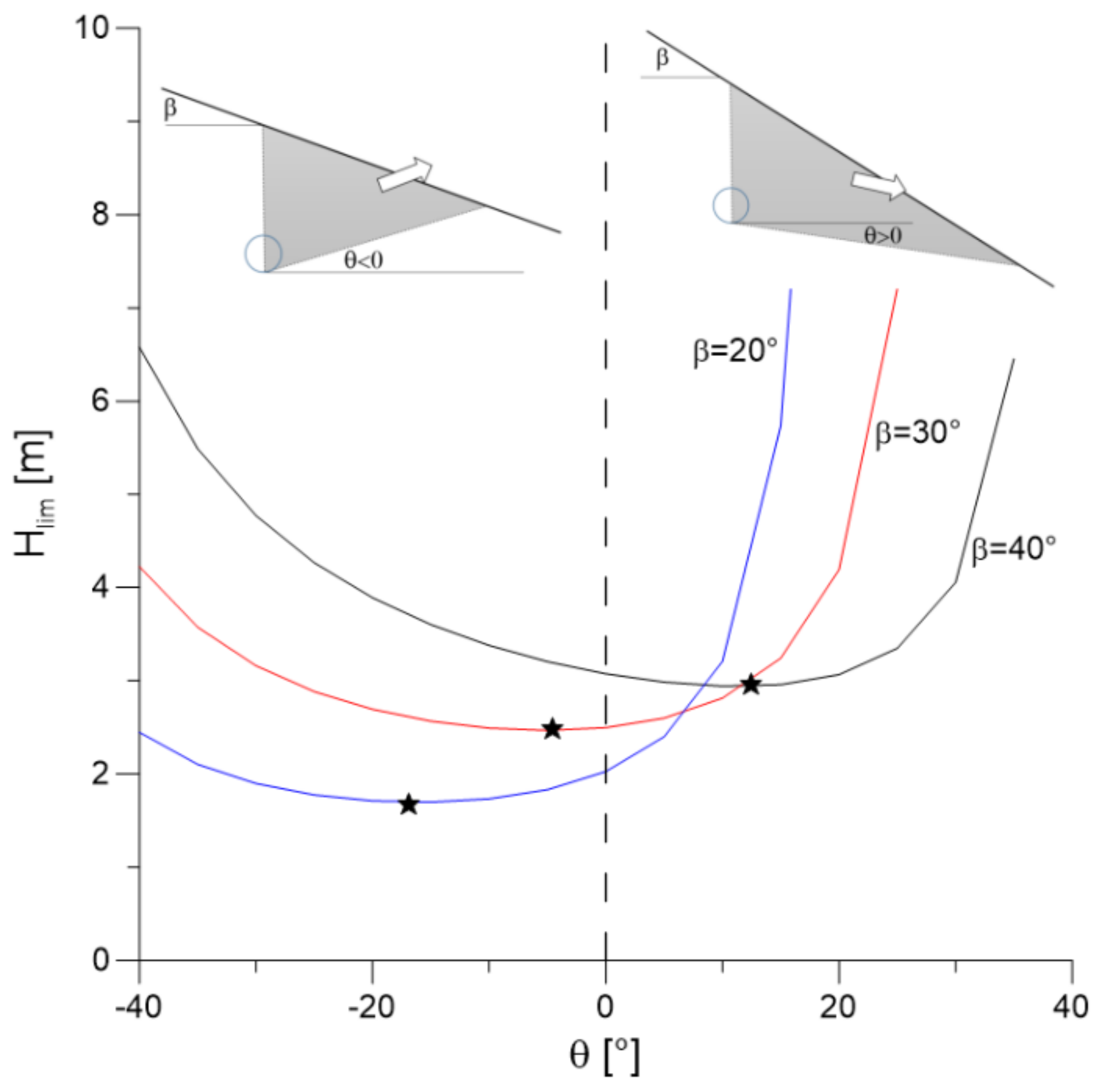
In Equation (1), the inclination of the sliding plane is unknown. Figure 4 shows the limit hydraulic head as function of for three different values of the slope angle; the stars indicate the minimum Hlim which is considered the reference solution. The slope inclination influences the failure mechanism, indeed for small values of , the minimum value of hydraulic head is obtained for , and the opposite is observed for steeper slopes.
The minimum of Equation (1) can be derived analytically, but the solution is relatively difficult, and can be achieved more easily numerically, thus a minimization procedure was implemented in MatLab R2022a to determine the angle providing the lowest limit hydraulic level for a given set of parameters. The live script to calculate Hlim is provided in the Supplementary Materials.
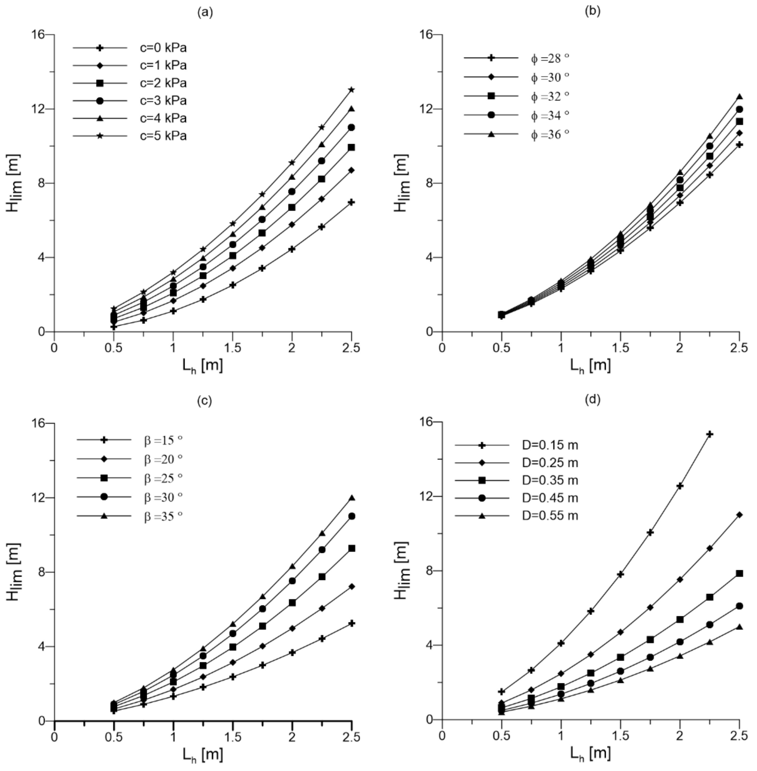
Figure 5 shows the limit hydraulic head as a function of Lh for different parameters. Hlim always increases with Lh, which means that this mechanism is unlikely for deep cavities. Cohesion c is the strength parameter that modifies Hlim the most; indeed, small values of c significantly increase Hlim for the same value of Lh (Figure 5a). In contrast, the friction angle has a limited impact (Figure 5b). The evaluation of soil shear strength parameters, especially cohesion, is not trivial because the superficial soil layer can be damaged by anthropic and natural factors during the service life of the levee. When increasing β, higher Hlim is obtained for the same Lh (Figure 5c). This is due to geometrical effects, in fact, for a constant Lh, the average depth of the sliding surface, as well as the length L′, increases, thus increasing the resistant forces. Cavities of a larger size drastically reduce the limit hydraulic head (Figure 5d): an increase of D by less than 10 cm can reduce Hlim by more than 50 cm.
In light of all the foregoing considerations, the risk of collapse in this simplified 2D mechanism is greater for large cavities in soils with small cohesion and when the dens are located near the land-side slope and at the base of the levee.
3. Bi-Dimensional Finite Element Analyses of the Stability of Landside Slope
Bi-dimensional finite element analyses were performed with MIDAS GST NX (v2019) [15] to evaluate the accuracy of the simplified method proposed in the previous section. The two approaches were compared in terms of shape of the unstable soil wedge and limit hydraulic head (Hlim).
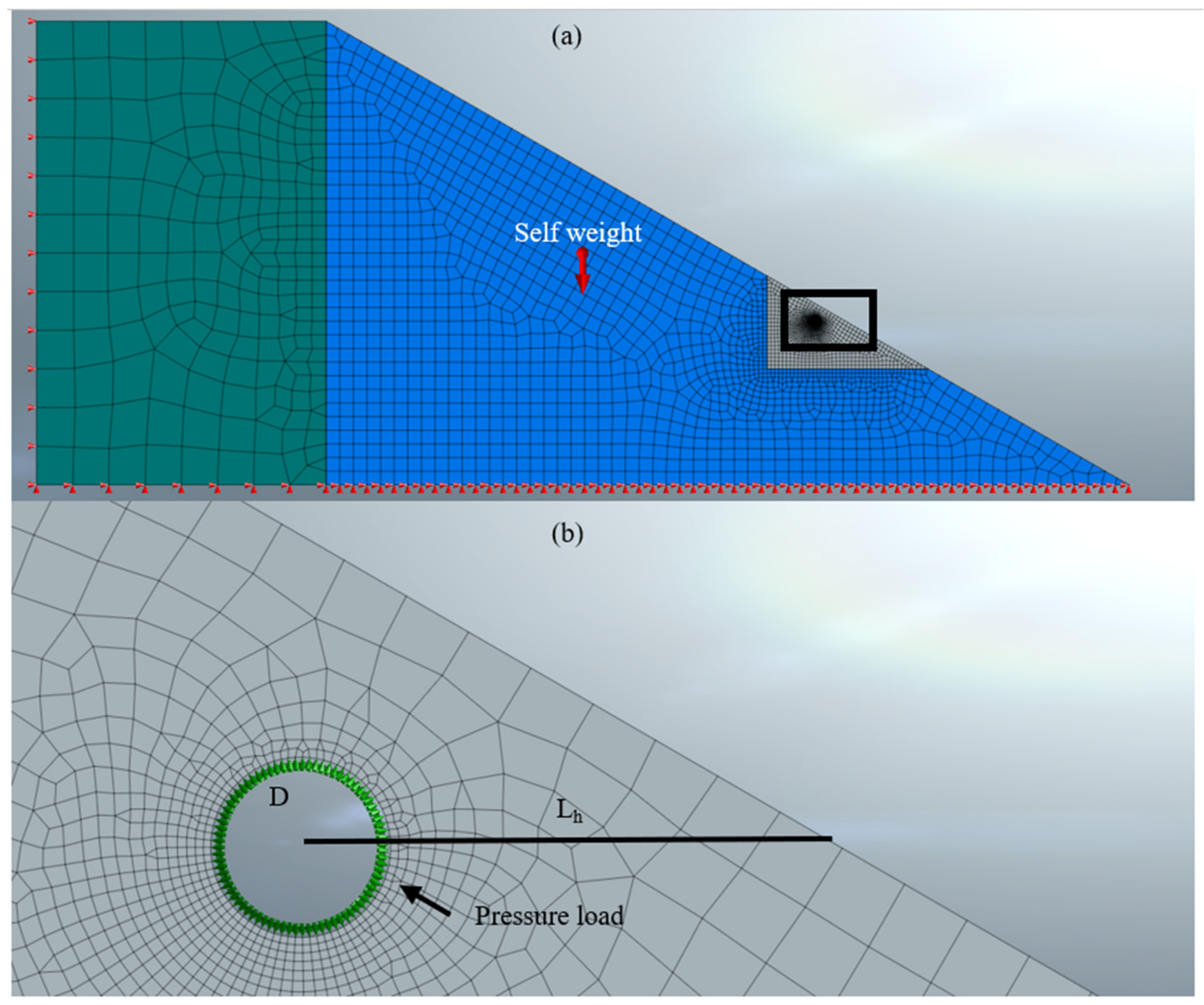
Since seepage effects were neglected, one-phase analyses were performed, and the governing equations of the numerical model are summarized in the Appendix A. Earth embankment was modelled with a homogeneous elastic perfectly plastic material, with reasonable strength and stiffness parameters, namely cohesion 3 kPa, friction angle 31°, Young modulus 30 MPa, Poisson’s ratio 0.3, and unit weight 18 kN/m3. These strength parameters are typical of sand–silt mixtures [16]. These materials often characterize the levee of the Po Plane in Italy; in particular, they are representative values of the case study of the Panaro river levee breach analyzed in Section 5 [17]. The cavity was assumed to be circular with a diameter D = 0.25 m and it was located at a variable distance Lh (0.75 m–1.00 m–1.25 m–1.50 m) from the outer surface, which was inclined at an angle β = 30°. Model geometry, discretization, and boundary conditions are shown in Figure 6.
The initial stress state was generated with gravity loading assuming an undamaged levee, before fauna’s intrusion. The burrow was successively simulated by deactivating the corresponding mesh. At this point, the water pressure, represented by a pressure load (), was applied at the boundary of the cavity (Figure 6b). The pressure corresponding to the point of failed convergence of FEM was considered as the failure load, from which Hlim was obtained.
The limit hydraulic head and the inclination of the failure plane are reported in Table 1 for FEM and LEM analyses for different values of Lh. FEM provided slightly larger Hlim compared to that of the simplified method.
The shape of the unstable soil wedge was graphically individuated at the interface between the non-zero ground displacement area and the stable levee’s portion. The failure kinematics are reported in Figure 7 with a dashed white line for the LEM simplified method (LLEM) and with a continuous black line for FEM analyses (LFEM). The shape of the moving soil mass and the inclination of the sliding planes of the two different approaches were similar for small values of Lh (Figure 7a). As the horizontal distance increased, the inclination of the sliding plane assumed an opposite rotation with respect to the horizontal, but the angle θ remained very small.
4. Three-Dimensional Finite Element Analyses of the Stability of Landside Slope
The real local failure mechanism is three-dimensional; in order to evaluate the importance of the geometrical effect, 3D finite element analyses were performed to evaluate the limit hydraulic head and the shape of the moving soil wedge to compare it with 2D results.
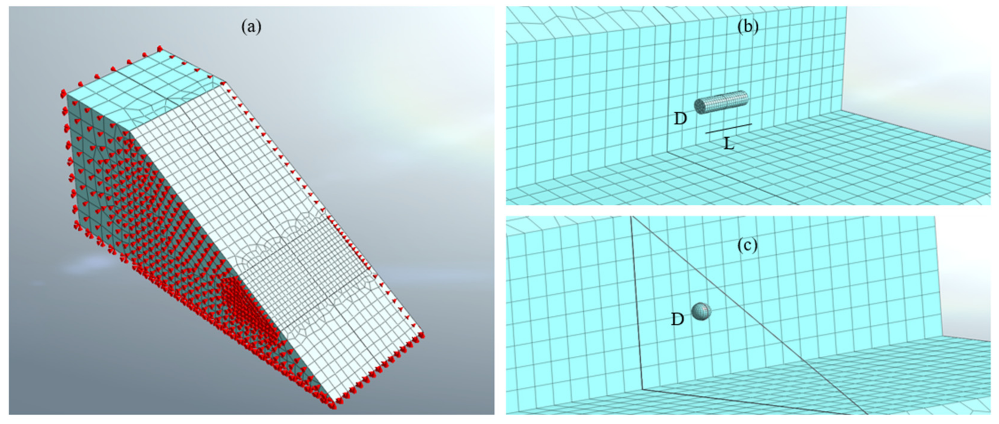
A real burrow system inside the earth embankment is hardly identifiable and therefore numerically replicable due to the diversity of the natural behavior and the mutual interaction between the different animal species living in a given ecosystem. For this reason, in the following analyses, we idealized an isolated cavity assuming two possible geometric shapes, namely a spherical shape (D = 0.25 m) and a cylindrical (D = 0.25 m and L = 1 m) shape, located at a variable distance Lh (0.75 m–1.00 m–1.25 m–1.50 m) from the outer surface, which was inclined at an angle β = 30°. Model geometry, discretization, and boundary conditions are shown in Figure 8. Loads and calculation phases were similar to the 2D case described in the previous section.
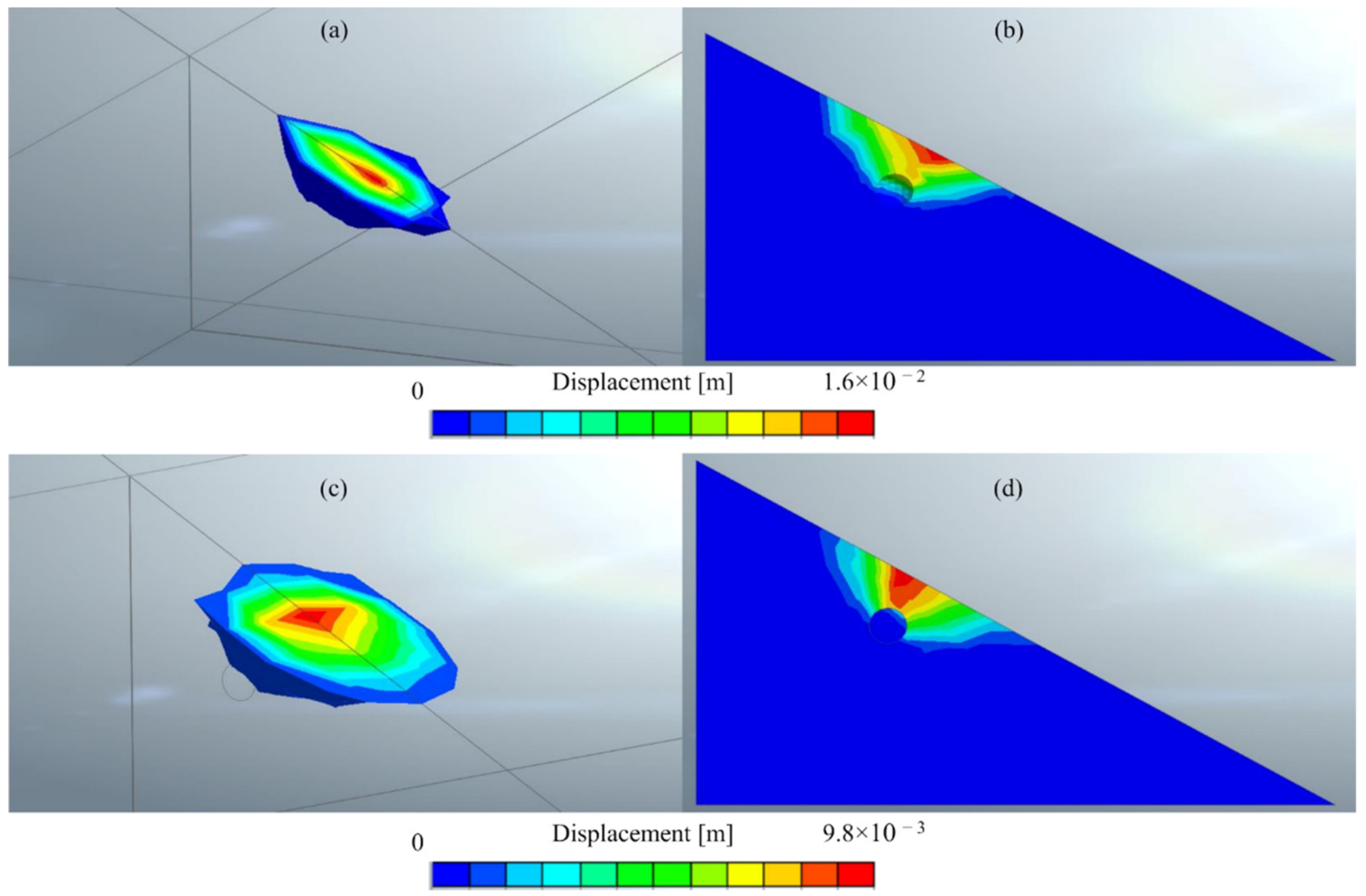
The limit hydraulic head is reported in Table 2 for the spherical and the cylindrical cavity: in both simulations, the 3D FEM limit hydraulic head increased with the increase of the horizontal distance between the cavity and the outer slope and, as expected, it was higher than in the corresponding 2D LEM and FEM analyses; Hlim was also greater for the spherical cavity than for the cylindrical one.
5. Documented Cases Possibly Attributable to This Mechanism
Failures attributable to the activity of animal burrows are numerous; see, e.g., the list published in [2] and, more recently, the cases reported in [5,17,18,19]. In most cases, an accurate reconstruction of the mechanism leading to failure (concentrated erosion, piping, global failure, etc.) is uncertain because of the lack of sufficient evidence. In this section, we discuss how the proposed mechanism could explain the rapid collapse observed in two well-documented case histories.
The first considered case is the failure of the Santa Clara Dam (Utah, USA) on 11 September 2012 during a storm event that filled the reservoir to the spillway. According to [19], in the early morning, the reservoir had filled to an elevation that was about 3 m below the spillway when the city public services director visited the dam to monitor its performance. Nothing unusual was noted during this visit, and the director of the Water Authority left the site to check the conditions in other areas of the city. Although the entrance of animal burrows may be hidden by vegetation and other obstacles, it can be assumed that an open hole could have been noticed during the inspection because this dam was poorly vegetated. When he returned 30 min later, the reservoir water level reached the spillway and he noted a leak described as a “jet of water” in the center of the dam, about 1.2 to 1.5 m below the crest (0.5 m below the reservoir water level), and two smaller leaks close to the main one. Concentrated erosion from the major leak led to the opening of the beach in about one hour. Experts analyzed different possible causes and concluded that the most likely the cause of failure was “rodent burrows that penetrated through or nearly through the embankment”.
The dam was homogeneous and made of silty sand and sandy silt, which are very erodible materials, with low cohesion. In early September 2012, a series of rainstorms moved across southwestern Utah, and the basin formed by the Santa Clara Dam had filled and drained during these storms without issue. However, this certainly increased the soil moisture, decreasing the apparent cohesion due to soil suction, and possibly enlarged pre-existing cavities.
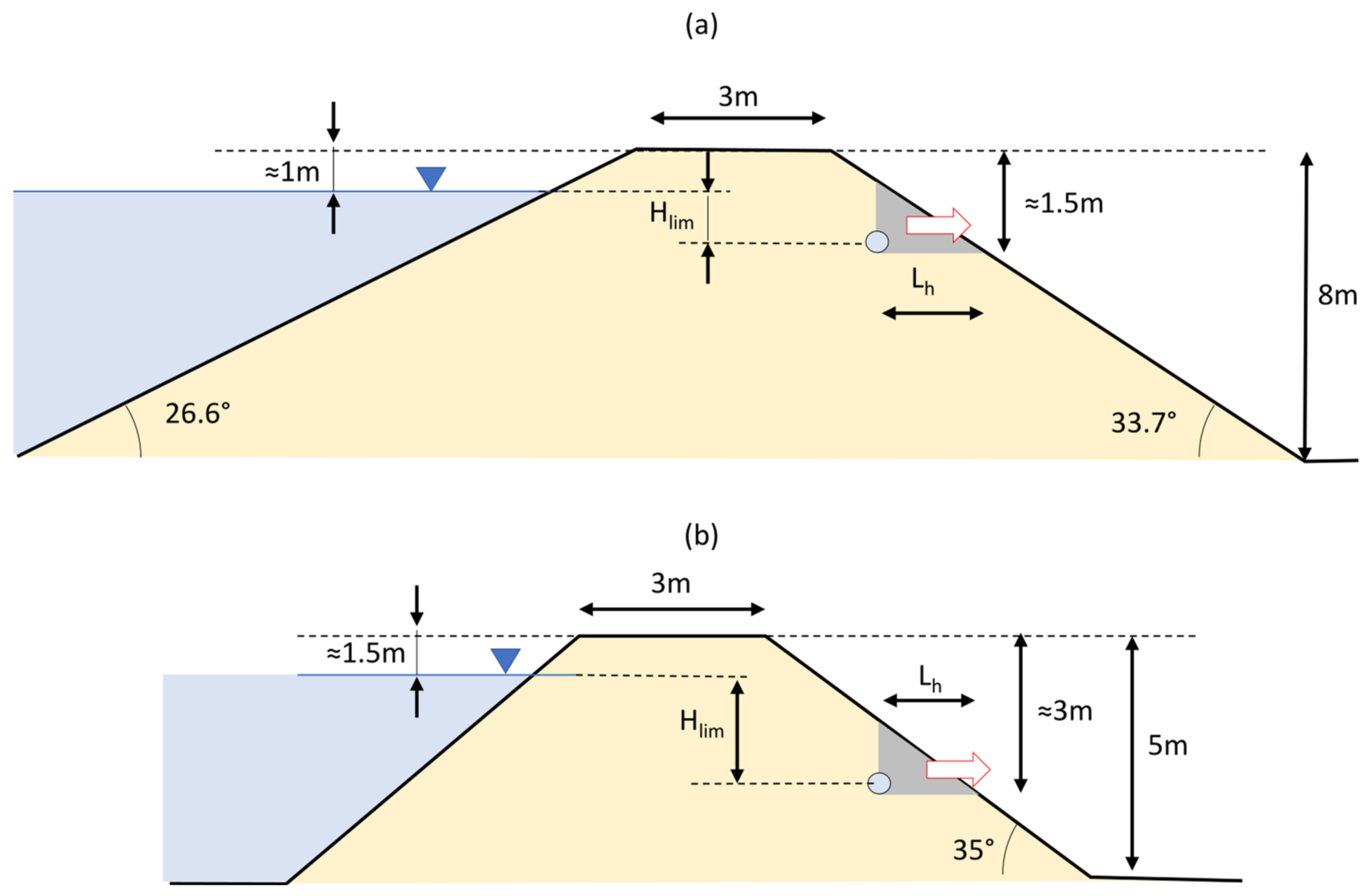
A schematic representation of the problem is given in Figure 10a. Assuming reasonable parameters for these materials, i.e., ϕ = 30°, c = 1 kPa, γ = 18 kN/m3, a cavity diameter D = 0.3 m, and a possible position of the cavity at Lh = 0.5 m, β = 33.7°, Equation (1) provides Hlim = 0.46 m, which is in very good agreement with field observations.
The second case is the breach of a levee of the Panaro River near Modena (Italy) that occurred on 6 December 2020, reported in [17]. The water level in the river increased almost 11 m in about 28 h. The structure suddenly failed around 6.00 a.m., with a freeboard of about 1.5 m, and enlarged during the same morning, reaching a length of 80 m. Experts concluded that the presence of a small cavity was the most likely cause of failure; moreover, there is evidence of local heterogeneities that could have facilitated the failure.
Burrowing animals such as porcupines, European badgers, nutria, and foxes are very active in the area, as testified by the presence of den entrances near the breach and the number of sightings reported by local people. Furthermore, concentrated erosion due to an animal burrow was observed in 2014 very close to this site, leading to a 3 m settlement of the crest being rapidly repaired, preventing breach opening [5]. In this case, the burrow was likely passing through the levee, as suggested by satellite photographs that clearly show the presence of the cavity on the landside [17].
The Regional Water Authority put in a significant effort to control the animal population and repair detected burrows. At the location of the breach, two animal burrows were detected on the land side and repaired in 2016 by tamping backfill soil into the holes. However, dens can be very long and with complex structures [20,21], thus, a complete reparation of the cavity system is often difficult and costly. It is possible that a part of the tunnel was still present within the embankment and filled with water during flooding. Moreover, lateritic elements and rhizomes of Arundo Donax were found in the spillway after the event [17], thus it cannot be excluded that the presence of the cavity could have had a different origin.
The earth embankment is made of a mixture of sand and silt in different proportions, and geotechnical investigations provide friction angles between 31 and 33 degrees and cohesions between 0 and 12 kPa. Since the soil between the surface and the cavity can be altered, lower values can be assumed.
The levee crest reached a height of 5 m from the landside ground level with a slope of 35°. Considering a cavity in the lower part of the structure, the hydraulic head would be between 1 and 2 m. The failure mechanism is represented in Figure 10b. Assuming D = 0.25 m, γ = 18 kN/m3, c = 3 kPa, ϕ = 31°, β = 35°, Equation (1) provides Hlim = 1.6 m for Lh = 0.7 m. This supports the hypothesis that a cavity, invisible from the surface, could have been the cause of failure.
6. Discussion
This study shows once again that the burrowing of animals in dams and levees can damage the earthen structures, increasing the probability of failure. One of the mechanisms that can rapidly lead to the opening of a breach is concentrated erosion through a pre-existing cavity fostering the formation of a pipe crossing the embankment. A local failure mechanism of a landside slope able to trigger concentrated erosion is proposed. This can occur when a cavity is buried at a shallow depth and the soil cover between the cavity and the surface is expulsed due to increasing water pressure.
This proves that the presence of cavities invisible from the surface, may severely threaten the safety of water-retention earth structures. Thus, it is important to monitor animal activity and encourage the development of new methods to detect the presence of small cavities inside levees. In the last decades, geophysical methods such as ground-penetrating radar and resistivity methods (ERT and FDEM) have been tentatively applied, see e.g., [20], but the procedures should be improved and made applicable at a large scale.
FEMA (2005) [1] recommends repairing animal burrows by completely filling the cavity with slurry; however, sometimes the holes are filled by soil tamping due to cost restrictions. In this case, it is important to ensure a sufficient soil cover; the new material should have adequate mechanical and hydraulic properties and be well compacted. Although this procedure is quick and economically affordable, it should be discouraged because it is very likely that a part of the tunnel remains open.
A simple equation based on 2D LEM was proposed to derive the hydraulic head above the cavity able to induce this type of failure. It was shown that the limit hydraulic head causing the collapse was mainly influenced by material cohesion, the diameter of the cavity, and distance from the surface. Soil friction angle and slope inclination had a minor effect. The proposed methodology is simple and applicable well to probabilistic approaches to improve the assessment of levee vulnerability to burrowing animals.
Finite element simulations are performed in 2D and 3D to confirm the assumed failure mechanism. The advantage of FEM is that the failure surface is a result of the simulation and not an assumption as in LEM. It is particularly interesting to note the very good agreement between the LEM and 2D FEM analyses both in terms of shape of the unstable wedge and predicted Hlim. Three-dimensional FEM analyses confirmed the essential features of the phenomenon but provided higher resistances. This means that the results obtained with Equation (1) were conservative, which is comforting considering that reconstructing the accurate volumetric shape of a buried cavity is extremely difficult or even impossible.
Seepage effects in soil are not considered explicitly; it is appropriate in the case of a rapid increase of water levels and materials with small permeability in unsaturated conditions that prevent significant seepage propagation through the soil. In reality, earthen structures are in partially saturated conditions, and soil suction offers additional strength which can be simplified as apparent cohesion [22,23]. This effect can be incorporated, adjusting the value of cohesion in Equation (1). Similarly, the effect of slope vegetation and soil alteration due to weathering can be considered with a proper estimate of shear strength parameters.
The triggering and progressing of the proposed failure mechanism have not yet been observed directly in the field. This is because visual documentation and measurements in real failure cases are not available; however, it seems to explain reasonably well the case of Sant Clara Dam (11 September 2008) and Panaro river levee (6 December 2020). Additional quantitative validation can only be achieved with full-scale tests.
7. Conclusions
This study shows that the presence of small cavities buried at shallow depths and in hydraulic communication with the reservoir can severely threaten the stability of dams and levees by inducing a local failure of the landside slope. This local failure creates a connection between the waterside and the landside through a pre-existing pipe. When the contact shear stress generated by the flow through the pipe exceeds the critical soil shear stress, the particles are eroded and the size of the conduct increases, leading very rapidly to the opening of the breach if no countermeasures are taken. This mechanism adds a new contribution to the panorama of endangering effects of animal burrows in dams and levees.
A simple equation to determine the hydraulic head above the cavity able to induce this type of failure was proposed based on a 2D LEM approach. Hlim was mostly influenced by material cohesion, the diameter of the cavity, and distance from the surface. Soil friction angle and slope inclination had a minor effect. The shape of the unstable soil wedge assumed in the simplified LEM approach was confirmed by the results of 2D and 3D FEM analyses.
The proposed methodology has the advantage of being very simple and computationally inexpensive; thus, it is applicable well to probabilistic approaches to enrich the assessment of levee vulnerability to burrowing animals at a large scale.
Supplementary Materials
The following supporting information can be downloaded at: https://www.mdpi.com/article/10.3390/w14182777/s1, MatLab code for solving Equation (1).
Author Contributions
Conceptualization, F.C. and P.S.; methodology, F.C. and P.S.; software, F.C. and S.M.; writing—original draft preparation, F.C. and S.M.; writing—review and editing, F.C. and P.S.; visualization, F.C. and S.M.; supervision, P.S. All authors have read and agreed to the published version of the manuscript.
Funding
This research received no external funding.
Institutional Review Board Statement
Not applicable.
Informed Consent Statement
Not applicable.
Data Availability Statement
Not applicable.
Conflicts of Interest
The authors declare no conflict of interests.
Appendix A
The software used for finite element analyses solves the momentum balance equation for static conditions, which can be written in strong form as Equation (A1):
where is the Cauchy stress tensor and is the body force. A variational (weak) form of this equation can be derived and yield the virtual work equation given by Equation (A2):
where is the virtual strain, is the virtual displacement, is the stress boundary condition, is the integration domain, and is its boundary. The superscript T indicates the transpose.
The stress is given by the constitutive equation
where D is the stiffness matrix.
Finite element approximation of virtual work and displacement is introduced as
where is the matrix of shape functions, B is the strain-displacement matrix (contains the derivatives of the shape functions), and is the nodal virtual displacement.
Substituting A3 and A4 in A2 and performing numerical integration, we obtain:
where and .
This formulation is exact for lineal materials but needs to be written in incremental and linearized form for nonlinear materials like soils and solved iteratively with the strategies typical of nonlinear finite element solvers. The interested reader is referred to the software manual for further details [15]
References
- FEMA Dam Owner’s Guide to Animal Impacts on Earthen Dams (FEMA L-264). 2005. Available online: https://www.fema.gov/sites/default/files/2020-08/fema-l264_dam_owners_guide_animal_impacts_earthen_dams.pdf (accessed on 12 January 2022).
- Bayoumi, A.; Meguid, M.A. Wildlife and Safety of Earthen Structures: A Review. J. Fail. Anal. Prev. 2011, 11, 295–319. [Google Scholar] [CrossRef]
- Harvey, G.L.; Henshaw, A.J.; Brasington, J.; England, J. Burrowing Invasive Species: An Unquantified Erosion Risk at the Aquatic-Terrestrial Interface. Rev. Geophys. 2019, 57, 1018–1036. [Google Scholar] [CrossRef]
- Haubrock, P.J.; Inghilesi, A.F.; Mazza, G.; Bendoni, M.; Solari, L.; Tricarico, E. Burrowing Activity of Procambarus Clarkii on Levees: Analysing Behaviour and Burrow Structure. Wetl. Ecol. Manag. 2019, 27, 497–511. [Google Scholar] [CrossRef]
- Orlandini, S.; Moretti, G.; Albertson, J.D. Evidence of an Emerging Levee Failure Mechanism Causing Disastrous Floods in Italy. Water Resour. Res. 2015, 51, 7995–8011. [Google Scholar] [CrossRef]
- Balistrocchi, M.; Moretti, G.; Ranzi, R.; Orlandini, S. Failure Probability Analysis of Levees Affected by Mammal Bioerosion. Water Resour. Res. 2021, 57, e2021WR030559. [Google Scholar] [CrossRef]
- Dassanayake, S.M.; Mousa, A. Probabilistic Stability Evaluation for Wildlife-Damaged Earth Dams: A Bayesian Approach. Georisk 2020, 14, 41–55. [Google Scholar] [CrossRef]
- Palladino, M.R.; Barbetta, S.; Camici, S.; Claps, P.; Moramarco, T. Impact of Animal Burrows on Earthen Levee Body Vulnerability to Seepage. J. Flood Risk Manag. 2020, 13, e12559. [Google Scholar] [CrossRef]
- Taccari, M.L. Study upon the Possible Influence of Animal Burrows on the Failure of the Levee of San Matteo along the Secchia River; Delft University of Technology: Delft, The Netherlands, 2015. [Google Scholar]
- Camici, S.; Barbetta, S.; Moramarco, T. Levee Body Vulnerability to Seepage: The Case Study of the Levee Failure along the Foenna Stream on 1 January 2006 (Central Italy). J. Flood Risk Manag. 2017, 10, 314–325. [Google Scholar] [CrossRef]
- Saghaee, G.; Mousa, A.A.; Meguid, M.A. Plausible Failure Mechanisms of Wildlife-Damaged Earth Levees: Insights from Centrifuge Modeling and Numerical Analysis. Can. Geotech. J. 2017, 54, 1496–1508. [Google Scholar] [CrossRef]
- Bonelli, S.; Nicot, F. Erosion in Geomechanics Applied to Dams and Levees; John Wiley & Sons, Inc.: Hoboken, NJ, USA, 2013; ISBN 9781848214095. [Google Scholar]
- Bonelli, S.; Brivois, O.; Lachouette, D. The Scaling Law of Piping Erosion. In Proceedings of the 18ème Congrès Français Mécanique, Grenoble, France, 27–31 August 2007; pp. 1–6. [Google Scholar]
- Savage, S.; Douglas, K.; Fell, R.; Peirson, W.; Berndt, R. Modeling the Erosion and Swelling of the Sides of Transverse Cracks in Embankment Dams. J. Geotech. Geoenviron. Eng. 2019, 145, 04019015. [Google Scholar] [CrossRef]
- MIDAS IT Co., Ltd. Midas GTS NX; MIDAS IT Co., Ltd.: Seongnam, Korea, 2020. [Google Scholar]
- Ojha, S.; Trivedi, A. Shear Strength Parameters for Silty-Sand Using Relative Compaction. Electron. J. Geotech. Eng. 2013, 18, 81–99. [Google Scholar]
- Menduni, G.; Cocchi, R.; Manselli, L.; Simonini, P. Commissione Tecnico-Scientifica per La Valutazione Delle Cause All’origine Della Rotta Arginale Lungo Il Fiume Panaro in Località Gaggio Di Castelfranco Emilia-Relazione Di Dettaglio. Int. J. Disaster Risk Reduct. 2021, 74, 102926. [Google Scholar]
- Taccari, M.L.; Van Der Meij, R. Investigation of the Influence of Animal Burrowing on the Failure of the Levee of San Matteo along the Secchia River. In E3S Web of Conferences; EDP Sciences: Les Ulis, France, 2016; Volume 9, pp. 1–6. [Google Scholar] [CrossRef]
- Marble, D. Santa Clara Dam Failure Memorandum to State Engineer Kent Jones. 2012. Available online: https://damfailures.org/wp-content/uploads/2022/01/Utah-Dam-Safety-Failure-Memo-Clean-Copy.pdf (accessed on 20 February 2022).
- Borgatti, L.; Forte, E.; Mocnik, A.; Zambrini, R.; Cervi, F.; Martinucci, D.; Pellegrini, F.; Pillon, S.; Prizzon, A.; Zamariolo, A. Detection and Characterization of Animal Burrows within River Embankments by Means of Coupled Remote Sensing and Geophysical Techniques: Lessons from River Panaro (Northern Italy). Eng. Geol. 2017, 226, 277–289. [Google Scholar] [CrossRef]
- Fischer, C.; Dunand, F. 3D Topography and Structure Analysis of Three European Badger (Meles Meles) Setts from Western Switzerland. Wildl. Biol. Pract. 2016, 12, 26–35. [Google Scholar] [CrossRef]
- Vanapalli, S.K.; Fredlund, D.G.; Pufahl, D.E.; Clifton, A.W. Model for the Prediction of Shear Strength with Respect to Soil Suction. Can. Geotech. J. 1996, 33, 379–392. [Google Scholar] [CrossRef]
- Fredlund, D.G. Unsaturated Soil Mechanics in Engineering Practice; John Wiley & Sons: Hoboken, NJ, USA, 2006; Volume 132, ISBN 9781118133590. [Google Scholar]
Figure 1.
Effect of animal burrows: (a) structural weakening, (b) altering pressure distribution, (c) favoring piping, (d) starting concentrated erosion.
Figure 1.
Effect of animal burrows: (a) structural weakening, (b) altering pressure distribution, (c) favoring piping, (d) starting concentrated erosion.

Figure 2.
(a) Typical burrows produced by crayfish Procambarus clarkii on irrigation ditches (adapted from [4]); (b) concentrated erosion though a mammal burrow in Panaro levee near Modena (Italy) (adapted from [5]. WILEY 2005); (c) mammal burrow found on the land side of the Panaro levee near Modena (Italy).

Figure 3.
Simplified failure mechanism (a) case θ > 0, (b) case θ < 0.

Figure 4.
Limit hydraulic head as function of inclination of failure surface; stars indicate the minimum point (D = 0.25 m, γ = 18 kN/m3, c = 3 kPa, ϕ = 31°, Lh = 1 m).
Figure 4.
Limit hydraulic head as function of inclination of failure surface; stars indicate the minimum point (D = 0.25 m, γ = 18 kN/m3, c = 3 kPa, ϕ = 31°, Lh = 1 m).

Figure 5.
Limit hydraulic level as function of Lh (if not otherwise specified D = 0.25 m, γ = 18 kN/m3, c = 3 kPa, ϕ = 31°, β = 30°): (a) effect of cohesion, (b) effect of friction angle, (c) effect of slope inclination, and (d) effect of the cavity diameter.
Figure 5.
Limit hydraulic level as function of Lh (if not otherwise specified D = 0.25 m, γ = 18 kN/m3, c = 3 kPa, ϕ = 31°, β = 30°): (a) effect of cohesion, (b) effect of friction angle, (c) effect of slope inclination, and (d) effect of the cavity diameter.

Figure 6.
(a) Discretization and boundary conditions of the numerical global model; (b) enlargement of the area around the cavity and definition of the problem characteristics.
Figure 6.
(a) Discretization and boundary conditions of the numerical global model; (b) enlargement of the area around the cavity and definition of the problem characteristics.

Figure 7.
Comparison between FEM and LEM failure kinematics for different values of Lh: (a) Lh = 0.75 m, (b) Lh = 1.00 m, (c) Lh = 1.25 m, (d) Lh = 1.50 m (D = 0.25 m, γ = 18 kN/m3, c = 3 kPa, ϕ = 31°, β = 30°).
Figure 7.
Comparison between FEM and LEM failure kinematics for different values of Lh: (a) Lh = 0.75 m, (b) Lh = 1.00 m, (c) Lh = 1.25 m, (d) Lh = 1.50 m (D = 0.25 m, γ = 18 kN/m3, c = 3 kPa, ϕ = 31°, β = 30°).

Figure 8.
(a) Discretization and boundary conditions of the numerical 3D global model; (b) representation of the cylindric tunnel portion into the embankment; (c) representation of the spherical den into the embankment.
Figure 8.
(a) Discretization and boundary conditions of the numerical 3D global model; (b) representation of the cylindric tunnel portion into the embankment; (c) representation of the spherical den into the embankment.

Figure 9.
Three-dimensional FEM failure kinematics: (a) 3D representation of the soil mass expelled by the static load applied inside the spherical cavity; (b) cross section of the failure mechanism associated with the spherical cavity geometry; (c) 3D representation of the soil mass expelled by the static load applied inside the cylindrical cavity; (d) cross section of the failure mechanism associated with the cylindrical cavity geometry.

Figure 10.
Schematic view of the proposed mechanism for (a) Santa Clara Dam and (b) Panaro levee.


Table 1.
Comparison between FEM and LEM limit hydraulic level for different values of Lh.
| Lh [m] | Hlim-LEM [m] | θLEM [°] | Hlim-FEM [m] | θFEM [°] |
|---|---|---|---|---|
| 0.75 | 1.60 | −6.8 | 1.75 | −6 |
| 1 | 2.45 | −5.2 | 2.75 | +4 |
| 1.25 | 3.50 | −3.6 | 3.75 | +5 |
| 1.5 | 4.69 | −2.3 | 4.74 | +6 |
Table 2.
Comparison between 3D FEM limit hydraulic level for different values of Lh and the den’s geometry.
Table 2.
Comparison between 3D FEM limit hydraulic level for different values of Lh and the den’s geometry.
| Lh [m] | Hlim-FEM 3D Sphere [m] | Hlim-FEM 3D Cylinder [m] |
|---|---|---|
| 0.75 | 12.01 | 3.55 |
| 1 | 16.29 | 5.57 |
| 1.25 | 22.75 | 7.26 |
| 1.5 | 23.50 | 9.77 |
Publisher’s Note: MDPI stays neutral with regard to jurisdictional claims in published maps and institutional affiliations. |
© 2022 by the authors. Licensee MDPI, Basel, Switzerland. This article is an open access article distributed under the terms and conditions of the Creative Commons Attribution (CC BY) license (https://creativecommons.org/licenses/by/4.0/).
Share and Cite
MDPI and ACS Style
Ceccato, F.; Malvestio, S.; Simonini, P. Effect of Animal Burrows on the Vulnerability of Levees to Concentrated Erosion. Water 2022, 14, 2777. https://doi.org/10.3390/w14182777
AMA Style
Ceccato F, Malvestio S, Simonini P. Effect of Animal Burrows on the Vulnerability of Levees to Concentrated Erosion. Water. 2022; 14(18):2777. https://doi.org/10.3390/w14182777
Chicago/Turabian StyleCeccato, Francesca, Stefano Malvestio, and Paolo Simonini. 2022. "Effect of Animal Burrows on the Vulnerability of Levees to Concentrated Erosion" Water 14, no. 18: 2777. https://doi.org/10.3390/w14182777
Note that from the first issue of 2016, this journal uses article numbers instead of page numbers. See further details here.