Article

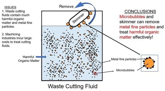
Treatment and Effective Removal of Metal Fine Particles from Waste Cutting Fluids by Flotation via Microbubbles and Skimming

1
Faculty of Agriculture and Marine Science, Kochi University, Nankoku 783-8502, Japan
2
Sakamoto-Giken Inc., Nankoku 783-0007, Japan
*
Author to whom correspondence should be addressed.
Present address: Kochi Study Center, The Open University of Japan, Akebono-cho, Kochi 780-8072, Japan.
Water 2022, 14(16), 2575; https://doi.org/10.3390/w14162575
Submission received: 5 August 2022 / Revised: 17 August 2022 / Accepted: 18 August 2022 / Published: 20 August 2022
(This article belongs to the Special Issue Advanced Engineering Design of Wastewater Treatment)

Abstract

:
Cutting fluids (CFs) are chemical liquids or aqueous emulsions of mineral (or synthetic) oil widely used in metal-machining processes. They contain toxic organic compounds and petroleum products, and spent CFs contain numerous small metal particles derived from the processing of metal workpieces. The iron fine particles (IFPs) in CFs can diminish the quality and precision of machine products. Machining industries purchase large amounts of CFs, which they must treat appropriately and from which they must remove the IFPs; therefore, cost-effective ways to treat spent CFs are needed. In this study, we evaluated the effectiveness of collecting and separating the IFPs and treating organic matter in spent CFs using microbubbles (MiBs). We found that numerous IFPs with sizes of ~1 μm were suspended in spent CFs and that they could be very effectively removed by bubbling with MiBs and skimming the surface of the CFs. The lifetime of the CFs could be doubled via this treatment. The cost for treating spent CFs using MiBs was 12% lower than the cost of traditional treatment. These results strongly suggest that bubbling with MiBs is a cost-effective and eco-friendly way to treat spent CFs.

Graphical Abstract

1. Introduction

Cutting fluids (CFs) are liquid chemicals or aqueous emulsions of mineral (or synthetic) oil that are widely used in metal-machining processes [1,2,3]. They are used to lower temperatures and lubricate the contact area between the cutting tool and the workpieces being processed to increase the durability of cutting machines [2,3,4]. Because the efficiency of the CFs often impacts on the quality of the metal-processing products, CFs are indispensable for the metal industries [5,6,7]. During the machining process, the amount of CF gradually decreases because of evaporation, and the desirable properties of the remaining CF are diminished. It is therefore necessary to replace spent CFs with fresh fluids [3]. The machining industries must therefore purchase large amounts of cutting fluids, the cost of which is a relatively large defrayal for the industries [4].
An additional concern is that CFs contain a lot of harmful and emulsified organic matter and many petroleum products [3,8]. The waste CFs can be serious sources of water pollution if they are leaked into rivers and/or aquifers without appropriate treatment [2,4]. Moreover, the waste CFs are often allowed to remain for long periods of time in industrial plants, where they rot and cause odor problems [2]. The machining industries therefore spend a lot of money treating the waste CFs. There is hence an urgent need for the machining industries to develop eco-friendly and inexpensive technologies to prevent or to minimize the generation of harmful CF waste and the release of CFs into the environment [2,5,9].
Another concern in the treatment of waste CFs is the metal-grinding swarf. The spent CFs are contaminated by a great deal of sludge, metal chips, and metal fine particles (MFPs) derived from the processing of metal workpieces. These contaminants adversely affect the workpieces that are produced. In particular, a high concentration of MFPs in the cutting fluids can reduce the quality and precision of the machine products by increasing the frictional drag of the treated surfaces and the number of burrs thereon. Therefore, the separation and removal of the MFPs from CFs are also very important for the maintenance of optimally clean and cool conditions during the cutting process [10].
Microbubbles (MiBs) are defined as bubbles with diameters of 1–100 µm. The unusual properties of the MiBs include their very large surface-to-volume ratios and ability to adsorb dissolved organic matter onto their surfaces. Because of these properties, MiBs have been used in many fields [11]. They have been used to supply dissolved oxygen (DO) to aquaculture fields [12,13,14,15], and to improve the water quality of wastewater contaminated with hazardous materials, such as phenol [16,17], palm oil [18], diesel oil [19], trichloroethylene [20], a particular surfactant [21], pesticides [22], and methylene blue [23]. We have already reported the use of MiBs to effectively treat the beverage-industry’s wastewater, and we have shown that relatively large amounts of organic matter contained in the effluents were removed quickly by supplying DO at a high rate to accelerate microbial decomposition [24].
Another useful application of MiBs is the adsorption of fine particles [25]. The organic and inorganic particles are adsorbed, condensed, and aggregated on the surface of microbubbles, and they can be separated by flotation [26]. MiBs have been used to separate and effectively remove palm oil from mill effluent [18], and diesel oil from sand [19]. The removal of microalgal cells [27] and pathogenic bacterial cells [28] by MiBs have already been reported. Sobhy and Tao [29] have also reported on the removal of fine coal particles by a nanobubble floatation system. These previous reports have suggested that the MFPs can be adsorbed onto the surface of the MiBs, then effectively floated to the water surface, and easily removed by a skimming technique [30]. However, because the MFPs have larger specific gravities than the microbial cells and coal particles, there is a possibility that the MFPs will not be effectively floated by the MiBs.
In the present study, the effectiveness of using MiBs and skimming systems to collect and separate the MFPs by floatation from the in-use CFs and to remove the harmful organic matter from spent CFs was evaluated, and a low-cost and eco-friendly process of treating waste CFs is proposed.

2. Materials and Methods

2.1. Experimental Conditions and Sample Collection

The experiments were carried out using two cutting machines with different cutting fluids. One machine was a model YZ-500 SG (Yamazaki Giken, Kochi, Japan) with an emulsion-type cutting fluid (E-CF) (Microcut 240T; Nihon Quaker Chemical, Ltd., Osaka, Japan). The E-CF was diluted tenfold to fifteenfold and then used to cut general structural steel (SS400), carbon steel (CS), and chromium molybdenum steel (SCM). The total volume of the in-use fluid was about 200 L. The other machine was a model MCH 630 (OKK Corporation, Hyogo, Japan) with a soluble-type cutting fluid (S-CF) (Clearcut R-HS-23B; NEOS, Kobe, Japan). Tenfold-diluted S-CF was used to cut the same types of steel (SS400, CS, SCM). The total volume of the in-use fluid was about 600–700 L.
The experiments were conducted from 20 August to 10 December 2018. During the experiments, both of the cutting machines were operated for 3–8 h per day. The particulate materials that floated to the surface of the in-use CFs were collected and removed by a skimmer (Tube Oil Skimmer ZVA8-08; Zebra Skimmers, Solon, OH, USA) during the machining process.
In both of the systems (E-CF and S-CF), the MiBs were first employed on 1 October. During the experiments, occasional supplements were made to the in-use fluid containers. The supplements consisted of freshly diluted CFs or tap water (10–30 L) for the E-CF system and of only tap water (100–130 L) for the S-CF system. The supplements were required because the evaporation and consumption during machining caused the total volume of cutting fluid to decrease. During the experiments, two subsamples of 100 mL from each cutting fluid (E-CF and S-CF) were collected from 5 cm below the surface of each container almost every day, using a siphon system. These samples were kept in a refrigerator until analysis.

2.2. Microbubbles

The microbubbles with an average diameter of 50 μm were generated via a gas–liquid shear system (Bubble Fresher BF152; Sakamoto-Giken Inc., Nankoku, Kochi, Japan) in which a gas shear field was created by swirling a liquid [31]. The microbubbles of air were supplied continuously to the in-use CF containers at a rate of 5 L min−1. One bubble generator was operated for 8 h per day for the E-CF system. Two generators were operated for 24 h per day to bubble the S-CF system.

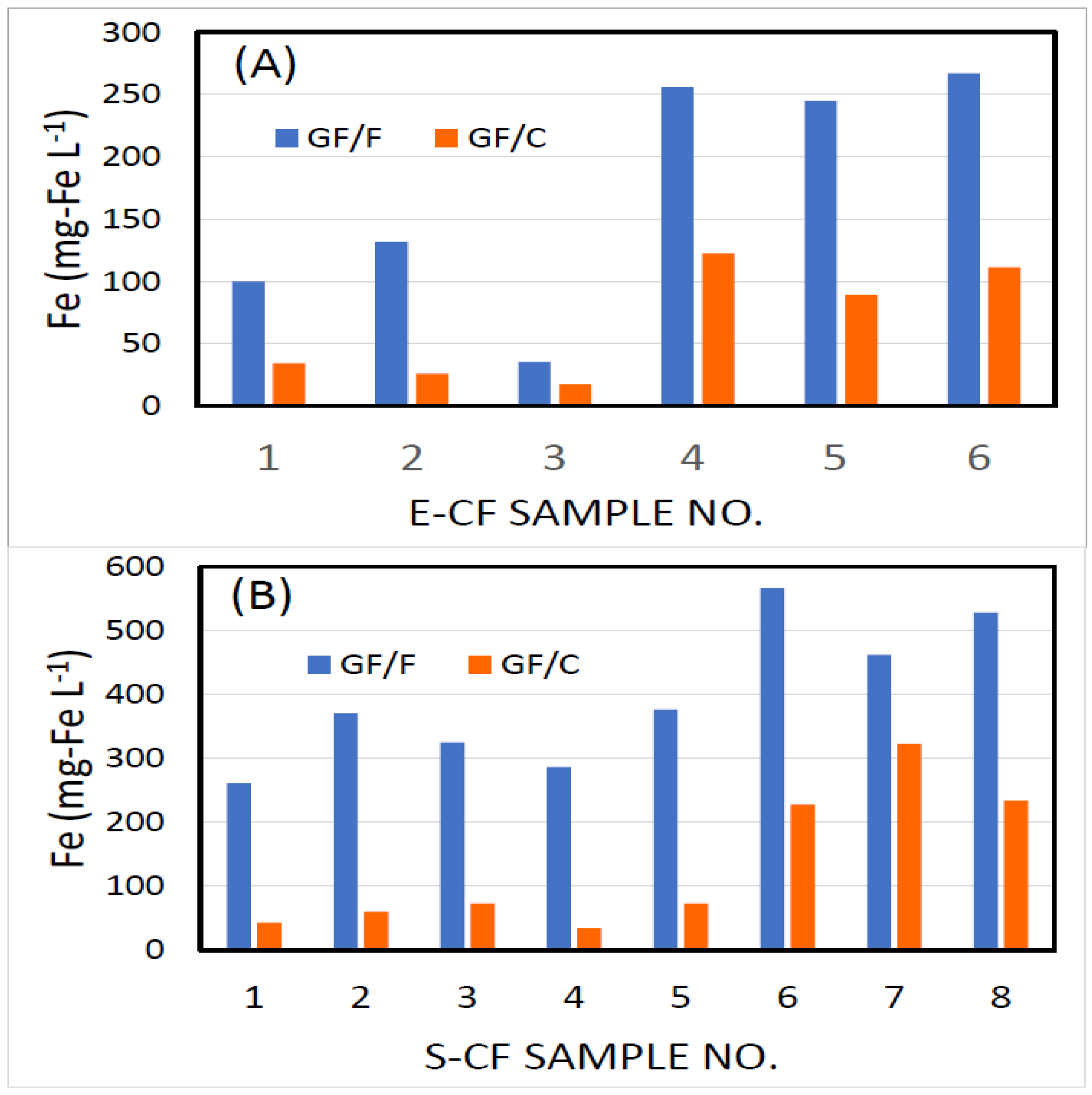
2.3. Concentrations of Iron Fine Particles (IFPs)

Because we assumed that the main component of the metal fine particles (MFPs) was iron, the concentrations of the iron fine particles (IFPs) suspended in the spent cutting fluids were determined by spectrophotometry (OD: 510 nm), using a 1,10-phenanthroline method [32]. The subsamples of 5–15 mL of CF collected on every sampling occasion were filtered through a GF/C or GF/F glass fiber filter (47 mm diameter; Whatman, Maidstone, UK) to collect the IFPs. The virgin filters were used as blanks. The filters were placed in 100-mL Erlenmeyer flasks, and 25 mL of distilled water (DW) was added. Five milliliters of 3N-HCL were then added to the flask, and the contents were boiled for 5 min. After cooling, the solutions were filtered through a GF/F filter to remove turbidity. Five to fifteen milliliters of the filtered subsamples were put into 50-mL volumetric flasks, and 1 mL of hydroxylamine hydrochloride (NH2OH HCL) solution (10% w/v in DW), 2.5 mL of ο-phenanthroline solution (0.12% w/v in DW), and a small piece of Congo red test paper was added. After adding 6N NH4OH dropwise until the color of the test paper changed to red, 2.5 mL of buffer solution (mixture of CH3COONa (final conc. of 6.8% (w/v)) and CH3COOH (final conc. of 2.9% (v/v), pH 4.6) was added and then diluted to 50 mL using DW. After keeping the solution at room temperature for 30 min, the optical densities of the solutions were measured with a spectrophotometer (Ultrospec 2000 UV/VIS Spectrophotometer, GE Healthcare Bioscience, Sweden). The optical densities of filter blanks were subtracted from those of the test solutions. The concentrations of the IFPs in the CFs were calculated, based on a standard curve prepared with FeSO4 (NH4)2SO4 6H2O.

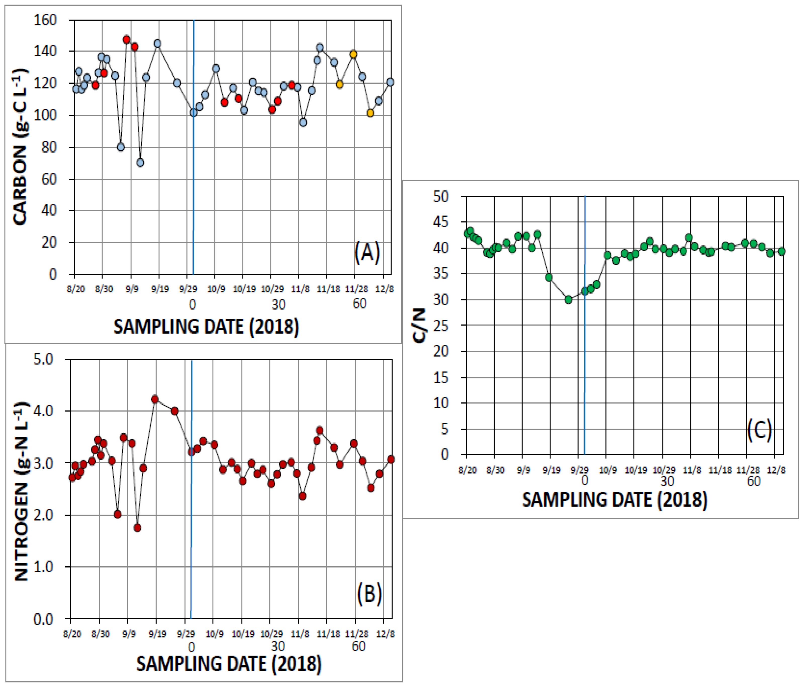
2.4. Determination of Organic Carbon and Nitrogen

The concentrations of organic carbon and nitrogen in the subsamples of cutting fluids (CFs) were determined with an NCH elemental analyzer (SUMIGRAPH NC-220F, Sumika Chemical Analysis Service. Ltd., Osaka, Japan). Fifty-microliter aliquots from each subsample collected at every sampling time were assayed with the NCH elemental analyzer. The measurements were completed in duplicate or triplicate at first. However, because the variation between the replicates was very small, single measurements were carried out after 9 October.

2.5. Monitoring of Odor

To determine the odor near the in-use CFs, we used a gas detection apparatus (Odor Level Indicator XP-329IIIR, New Cosmos Electric Co., LTD., Osaka, Japan) to monitor another S-CF system. The monitoring was performed at 1-min intervals. The gas samples of 400 ± 150 mL min−1 were collected automatically by the equipment from 10–20 cm above the water surface of the CF container. The data were plotted as relative averages of every 30 values.

2.6. Determinations of pH

The determination of the pH values of E-CF and S-CF were carried out on every sampling occasion, using two or three products of pH test papers with different pH ranges and scales (EMD; Millipore Corporation, Darmstadt, Germany).

3. Results

During the incubation, the water temperature in the E-CF container varied between 26.0 °C in late August to 13.5 °C at the end of the experiment (10 December). The temperatures in the S-CF container varied between 31.0 °C on 31 August to 12.0 °C on 10 December.

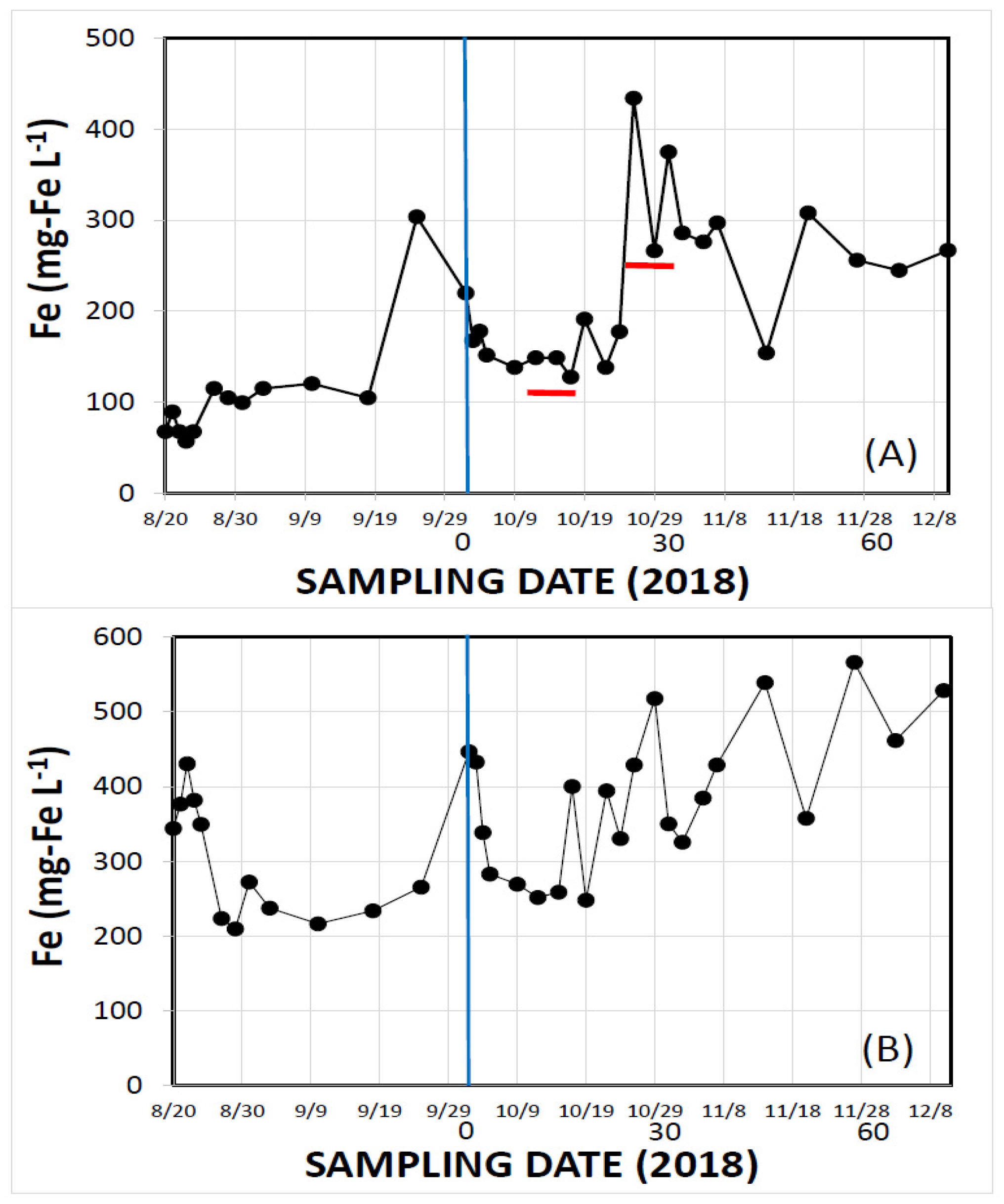
3.1. Changes in IFP Concentrations

When the concentrations of the IFPs retained on the GF/F filters (mesh size: 0.7 μm) and GF/C filters (1.2 μm) were compared in a preliminary experiment, the concentrations of both E-CF (Figure 1A) and S-CF (Figure 1B) were higher on the GF/F filters. The amounts of the IFPs retained on the GF/F filters were 2.57 times (E-CF) and 2.98 times (S-CF) the amounts retained on the GF/C filters. We therefore decided to use the GF/F filters thereafter.
Figure 2 shows the changes in the concentrations of the IFPs in the E-CF and S-CF. Before the bubbling of the CFs with the MiBs was initiated on 1 October, the concentrations of the IFPs gradually increased in both the E-CF and S-CF. After 1 October, the IFP concentrations decreased in both the E-CF and S-CF.
However, when the bubbling with the MiBs was stopped twice in the E-CF (horizontal red bars in Figure 2A), the IFP concentrations increased again, and after bubbling the CF containers with the MiBs was resumed, the IFP concentrations decreased. In the S-CF, the concentrations of the IFPs gradually increased after late October until the end of the experiment (Figure 2B).

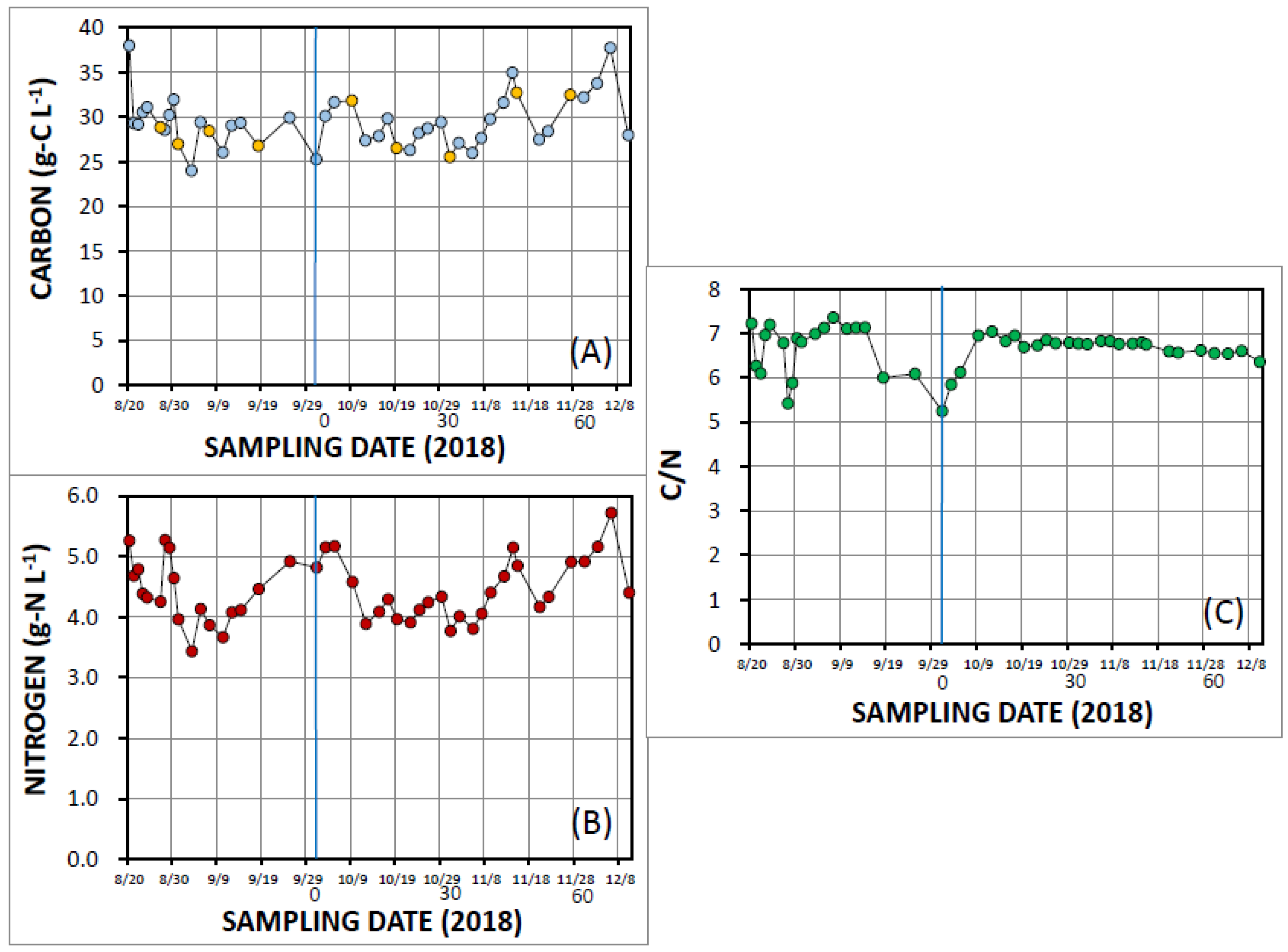
3.2. Changes of Carbon and Nitrogen Concentrations

The concentrations of organic carbon and nitrogen in the tenfold diluted fresh E-CF were 86.2 g-C L−1 and 2.01 g-N L−1, respectively; the carbon: nitrogen ratio (C/N) was 42.8. Figure 3 shows the fluctuations of the concentrations of organic carbon and nitrogen, and the C/N ratios in the E-CF. The times when the E-CF was diluted with fresh E-CF or tap water are indicated by red circles and orange circles, respectively, in Figure 3A. As described in the Materials and Methods section, the bubbling with the MiBs was initiated on 1 October (vertical blue lines in Figure 3A–C).
The concentrations of organic carbon and nitrogen in the E-CF were 70–148 (average 119 ± SD 15.4) g-C L−1 and 1.75–4.23 (average 3.03 ± SD 0.43) g-N L−1, respectively (Figure 3A,B). These concentrations were 1.4 times (C) and 1.5 times (N) the concentrations in the fresh E-CF, probably because of the evaporation and accumulation of organic compounds in the CF containers while the steel was being cut. The C/N ratios were all within the range 30–44 (average 39.4 ± SD 2.9) (Figure 3C). After bubbling with the MiBs (on 1 October), the carbon concentrations remained relatively constant, whereas the nitrogen concentrations decreased gradually (Figure 3A,B). The result was an increase of the C/N ratios from ~30 to over 40 within 10 days. After that time, the C/N ratios were almost constant (Figure 3C). Although fresh E-CF (red circles) or tap water (orange circles) were added occasionally (Figure 3A), the effects of the additions on the concentrations of carbon and nitrogen were unclear.
Similarly, the concentrations of organic carbon and nitrogen in S-CF varied in the range 24.0–38.0 (average 29.5 ± SD 2.95) g-C L−1 and 3.44–5.72 (average 4.45 ± SD 0.51) g-N L−1, respectively (Figure 4A,B). The C/N ratios were almost constant and averaged 6.66 ± SD 0.45. Because the S-CF contained only about 25% as much carbon but 147% as much nitrogen as the E-CF on average, the C/N ratios were much lower in the S-CF than in the E-CF. There were no clear differences in the C/N ratios during the ~40 days before and ~70 days after bubbling with the MiBs (Figure 4C), although the C/N ratios increased abruptly from 5.25 to 7.04 just after bubbling with the MiBs and then remained nearly constant (Figure 4C).

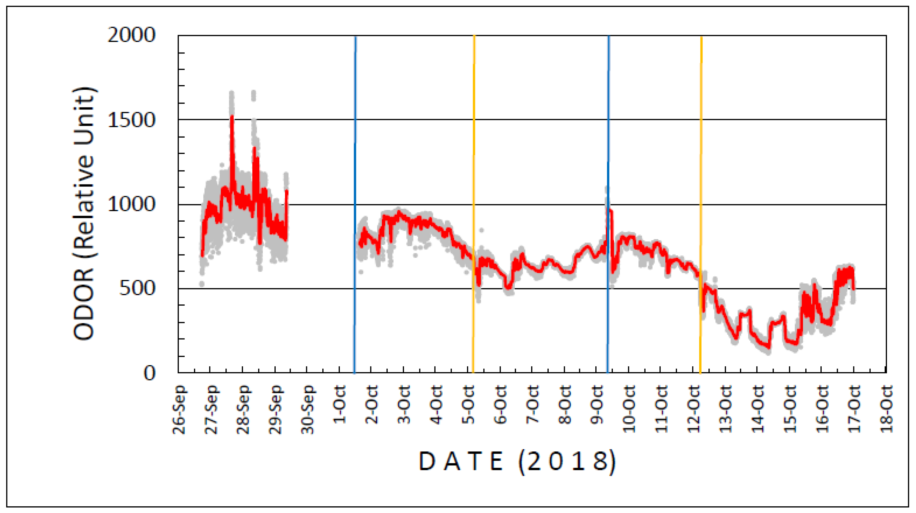
3.3. Fluctuations of Odor
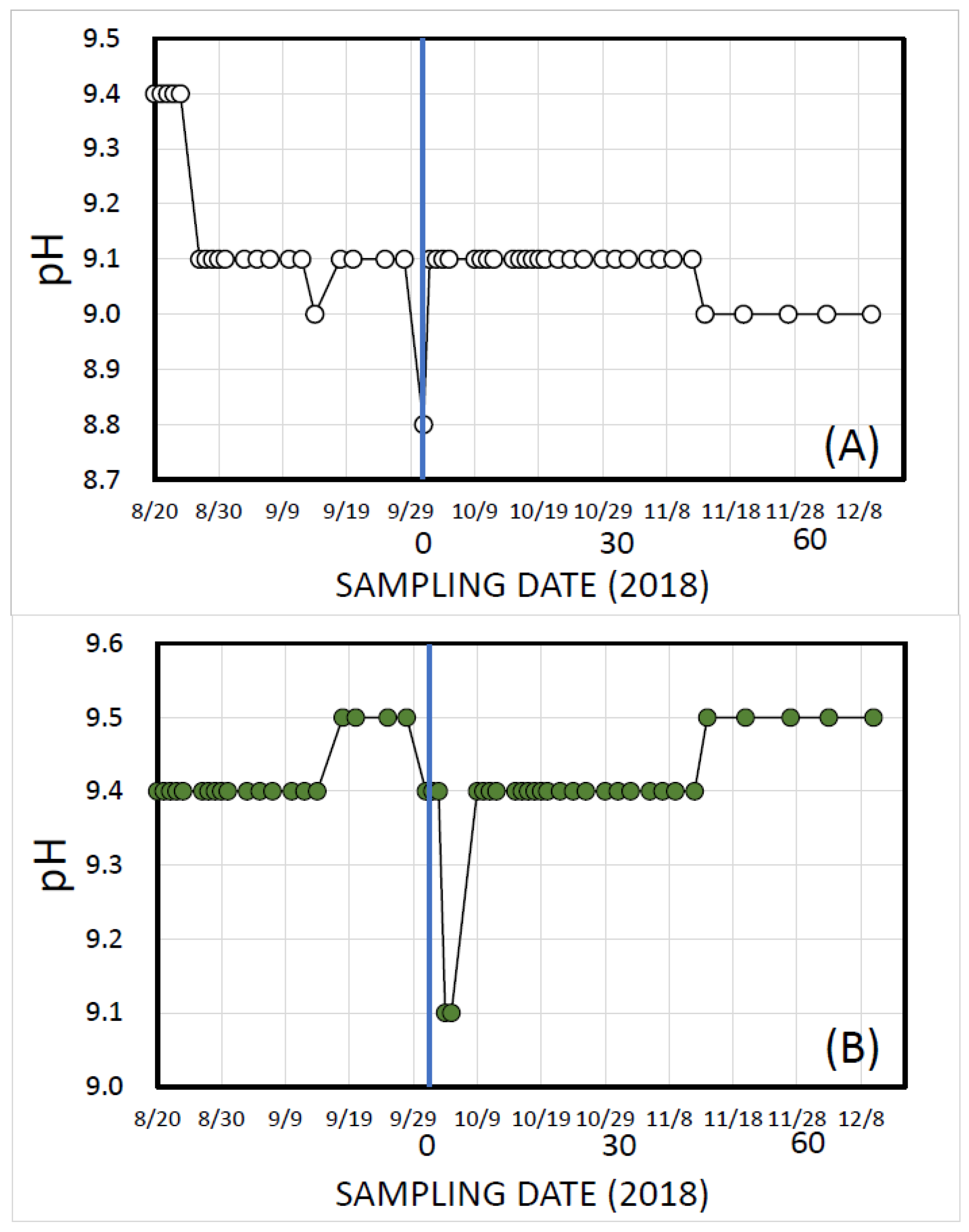
Figure 5 shows the changes of odor near the S-CF container while the S-CF was being used. Before bubbling with the MiBs, the relative units of odor were ~1000. However, after the bubbling of the CF system with the MiBs was initiated on 1 October, the levels of odor decreased gradually to 600 on 5 October. The odor level increased again when the bubbling with the MiBs was stopped from 5–9 October. However, after the bubbling with the MiBs was resumed on 9 October, the odor level decreased significantly to 400 by 13 October (Figure 5).

3.4. Changes in pH

The pH of the diluted fresh E-CF was 10.0. During the experiments, the pHs decreased and were within the range 8.8–9.4 in the E-CF container (Figure 6A) and 9.1–9.5 in the S-CF container (Figure 6B). The variations in the pH during the experiments were very small. There were no clear changes of pH before and after bubbling with the MiBs in either the E-CF or S-CF container.

4. Discussion

In the present study, we evaluated the effectiveness of using the MiBs to treat spent CFs. We found that bubbling with the MiBs did not change the concentrations of organic carbon by much during the machining process with either E-CF or S-CF (Figure 3A and Figure 4A).
Various methods to treat and dispose of waste CFs have been proposed [4,7,8,33]. Shimizu and Suzuki [34] treated water-soluble metalworking fluids via an anion-exchange, membrane-electrodialysis system to recycle the fluids and extend their lifetime. Zelenko et al. [3] reported that after treating spent CFs with various surfactants, only two products, water and sludge, remained.
Demirbas and Kobya [35] reported that relatively large amounts of chemical oxygen demand (COD) and total organic carbon (TOC) are removed by chemical or electro-coagulation methods. Wang et al. [36] used a combination of chemical and biological treatments using poly-aluminum chloride and cationic polyacrylamide for coagulation (chemical process) and an anaerobic hydrolysis-aeration system as a biological treatment. They have reported that 99.4% of the TOC and almost 100% of the oil are removed from the waste CFs. Mofrad et al. [37] treated metalworking fluid wastewater using a chemical addition–dissolved air floatation system and reported that the COD and total petroleum hydrocarbons were reduced by 99.9% and 97.9%, respectively. Pacholski and Sęk [38] proposed the use of a demulsifier to separate the oil and water from the emulsified cutting fluids. The goal of all of these studies has been an eco-friendly treatment that involves recycling and reuse of the lubricant oil or the drainage of spent cutting fluids to avoid pollution of natural environments.
A previous report showed that bubbling 30 L of beverage-industry wastewater with MiBs at 5 mL min−1 resulted in effective decomposition and removal of organic carbon [24]. The rate of supply of the MiBs was calculated to be 7.2 L day−1, about 24% (v/v) of the rate of the wastewater production. In the present study, the MiBs were supplied at a rate of 300 L h−1 to the E-CF container (vol. 200 L) for 8 h per day and continuously at a rate of 600 L h−1 to the S-CF container (vol. 600–700 L). The bubbling with the MiBs was therefore 12 times the volume of E-CFs per day, and 21–24 times the volume of S-CF per day. Under these conditions, the concentrations of the organic carbon and nitrogen did not clearly decrease (Figure 3 and Figure 4). These results appeared to show that bubbling with the MiBs to treat CF waste was not very effective. However, the concentrations of organic carbon and nitrogen did not increase (Figure 3 and Figure 4), although some fresh CFs were supplied occasionally to the CFs while they were being used, and the odor problem was significantly suppressed from more than 1000 to less than 200 relative units (Figure 5). According to the information provided by the company that made the odor-measuring equipment, an odor level greater than 1000 is “serious” and a level of 200 is below the odor-detection threshold [39]. The results therefore suggested that bubbling with the MiBs was effective enough to suppress the accumulation of organic matter in the CF containers. In this study, however, the chemical composition of the organic matter in the waste CFs was not determined. The changes in the chemical composition of the organic matter in CFs during bubbling with the MiBs, especially chemicals that might cause odor problems, must be monitored in a future study.
In contrast, we found that bubbling with the MiBs was an effective way to remove the MFPs from waste CFs. The results of a preliminary experiment clearly revealed that the amounts of the retained IFPs were unexpectedly much greater on a GF/F filter (>0.7 μm) than on a GF/C filter (>1.2 μm) (Figure 1). The implication was that the waste CFs contained large amounts of very fine metal particles with sizes of ~1 μm. To the authors’ knowledge, this study is the first to report this discovery. As mentioned in the Introduction, a high density of MFPs in cutting fluids reduces the quality and precision of machined products by increasing friction and burrs on the treated surfaces.
The methods to separate and remove metal particles have traditionally included centrifugation [40], membrane filtration [41], and magnetic attraction [42,43]. However, none of these methods are effective for treating large amounts of waste CFs containing very fine metal particles. Magnetic attraction can remove only steel particles and is incapable of removing other non-magnetic metals. We used the tendency of the MiBs to adsorb and aggregate fine particles on their surfaces in floatation separation systems. Very few studies have evaluated the efficiency of removing fine particles of ferric hydroxide by flotation using microbubbles and nanobubbles [44].
The results obtained in the present study showed that the concentrations of the IFPs with sizes of ~1 μm gradually increased during the metal processing, but by bubbling the CFs while they were being used and using a skimming apparatus, we significantly reduced the concentrations of the IFPs in the CFs (Figure 2). This result suggested that bubbling with the MiBs and using a skimming system was an effective way to remove the MFPs from both E-CFs and S-CFs (Figure 2).
Finally, we tried to estimate the cost of treating the waste CFs using the MiBs and compared that with the cost of traditional treatment. We assumed the volume of in-use CF to be 360 L and the lifetime of the CF to be one year. We estimated the annual costs of purchasing and disposing of the CFs to be USD359 and USD11, respectively. The annual cost of labor was estimated to be USD577. The costs were therefore about USD1047 per year. In contrast, assuming that the lifetime of CFs was to be doubled by bubbling with the MiBs and the cost of one MiB generator to be USD754, the cost, including electricity (USD26), was calculated to be USD1139 for the first year. However, the cost decreased to USD714 in the second year because only electricity (USD26) and the costs of labor (USD577) and waste disposal (USD111) for CF treatment were necessary. The cost for two years was therefore USD2094 for conventional treatment and USD1853 for treatment with the MiBs. The cost with the MiB treatment was therefore reduced by ~12%. Although the costs were reduced by only 12%, the amount of harmful CF waste was decreased by ~50%, and the treatment of the spent CFs and the removal of MFPs using MiBs were low-cost, eco-friendly processes.

5. Conclusions

In the present study, we evaluated the effectiveness of MiBs with diameters of ~50 μm for treating spent CFs. In a preliminary experiment, we showed that large amounts of MFPs with sizes of ~1 μm were produced and suspended in spent CFs during machining. A high concentration of the MFPs in the cutting fluids reduces the quality and precision of the machined products by increasing the friction and number of burrs on the treated surfaces. Our results showed that the concentration of the IFPs (representative MFPs) gradually increased during the metal processing, but the concentrations of the IFPs were decreased significantly by bubbling the CF during its use with the MiBs and skimming the surface of the CF. The implication was that the MiBs were effective in removing the MFPs. Bubbling with the MiBs, however, did not decrease the concentration of organic matter in CFs, but it did significantly suppress the odor problems, and the lifetime of the CFs was doubled. The cost of treating spent CFs using the MiBs was calculated to be 12% lower than the cost of traditional treatment. These results strongly suggest that bubbling with the MiBs combined with the use of a skimming system can remove the MFPs and increase the lifetime of CFs. The amount of harmful CF waste can thereby be reduced by a factor of two. This methodology is an inexpensive and eco-friendly new process for the treatment of CF waste.

Author Contributions

Conceptualization, K.F., K.Y. and M.S.; methodology, K.F., N.O., K.Y. and K.K.; validation, K.F.; formal analysis, K.F.; investigation, K.F. and K.Y.; resources, K.Y., K.K. and I.M.; data curation, K.F., N.O. and K.Y.; writing—original draft preparation, K.F.; writing—review and editing, K.F.; visualization, K.F.; supervision, K.Y. and M.S.; project administration, K.F. and M.S.; funding acquisition, M.S. All authors have read and agreed to the published version of the manuscript.

Funding

This study was conducted with support from the Kochi Research and Development Fund, and part of this study was financially supported by the “research fund for the director” of the Open University of Japan.

Institutional Review Board Statement

Not applicable.

Informed Consent Statement

Not applicable.

Data Availability Statement

Not applicable.

Acknowledgments

The authors thank Kochi Prefecture, Japan, for its financial support of this study. The authors also give their sincere gratitude to the Open University of Japan, for its financial support. The authors thank Takashi Hata of the National Institute of Technology (KOSEN) Kochi College for his help in obtaining the Kochi Research and Development Fund.

Conflicts of Interest

The authors declare no conflict of interest. The funders had no role in the design of the study; in the collection, analyses, or interpretation of data; in the writing of the manuscript, or in the decision to publish the results.

References

  1. Sokovic, M.; Mijanovic, K. Ecological aspects of the cutting fluids and its influence on quantifiable parameters of the cutting processes. J. Mater. Process. Technol. 2001, 109, 181–189. [Google Scholar] [CrossRef]
  2. Lee, C.-M.; Choi, Y.-H.; Ha, J.-H.; Woo, W.-S. Eco-friendly technology for recycling of cutting fluids and metal chips: A review. Int. J. Precis. Eng. Manuf. Green Technol. 2017, 4, 457–468. [Google Scholar] [CrossRef]
  3. Zelenko, Y.; Bezovska1, M.; Kuznetsov, V.; Muntian, A. Technological and Ecological Aspects of Disposal of Spent Cutting Fluids. J. Ecol. Eng. 2021, 22, 207–212. [Google Scholar] [CrossRef]
  4. Najiha, M.S.; Rahman, M.M.; Yusoff, A.R. Environmental impacts and hazards associated with metal working fluids and recent advances in the sustainable systems: A review. Renew. Sustain. Energy Rev. 2016, 60, 1008–1031. [Google Scholar] [CrossRef]
  5. Jagadevan, S.; Graham, N.J.; Thompson, I.P. Treatment of waste metalworking fluid by a hybrid ozone-biological process. J. Hazard. Mater. 2013, 244–245, 394–402. [Google Scholar] [CrossRef]
  6. Waydande, R.; Ghatge, D. Performance evaluation of different types of cutting fluids in the machining of hardened steel—A review. Int. J. Mech. Prod. Eng. 2016, 4, 34–39. [Google Scholar]
  7. Abdelrazek, A.H.; Choudhury, I.A.; Nukman, Y.; Kazi, S.N. Metal cutting lubricants and cutting tools: A review on the performance improvement and sustainability assessment. Int. J. Adv. Manuf. Technol. 2020, 106, 4221–4245. [Google Scholar] [CrossRef]
  8. Jamaly, S.; Giwa, A.; Hasan, S.W. Recent improvements in oily wastewater treatment: Progress, challenges, and future opportunities. J. Environ. Sci. 2015, 37, 15–30. [Google Scholar] [CrossRef]
  9. Murić, A.; Petrinić, I.; Christensen, M.L. Comparison of ceramic and polymeric ultrafiltration membranes for treating wastewater from metalworking industry. Chem. Eng. J. 2014, 255, 403–410. [Google Scholar] [CrossRef]
  10. Kuroki, T.; Watanabe, H.; Okubo, M.; Yamamoto, T. Regeneration technology of cutting oil using electrolytic bubble flotation method. Simultaneous removal of fine aluminum particles and sludge contaminant. IEEJ Trans. Ind. Appl. 2006, 126, 330–336, (In Japanese with English Abstract). [Google Scholar] [CrossRef]
  11. Temesgen, T.; Bui, T.T.; Han, M.; Kim, T.-I.; Park, H. Micro and nanobubble technologies as a new horizon for water-treatment techniques: A review. Adv. Colloid Interface Sci. 2017, 246, 40–51. [Google Scholar] [CrossRef] [PubMed]
  12. Srithongouthai, S.; Endo, A.; Inoue, A.; Kinoshita, K.; Yoshioka, M.; Sato, A.; Iwasaki, T.; Teshiba, I.; Nashiki, H.; Hama, D.; et al. Control of dissolved oxygen levels of water in net pens for fish farming by a microscopic bubble generating system. Fish. Sci. 2006, 72, 485–493. [Google Scholar] [CrossRef]
  13. Endo, A.; Srithongouthai, S.; Nashiki, H.; Teshiba, I.; Iwasaki, T.; Hama, D.; Tsutsumi, H. DO-increasing effects of a microscopic bubble generating system in a fish farm. Mar. Pollut. Bull. 2008, 57, 78–85. [Google Scholar] [CrossRef] [PubMed]
  14. Colt, J.; Kroeger, E.; Rust, M. Characteristics of oxygen flow through fine bubble diffusers used in the aquaculture hauling applications. Aquac. Eng. 2010, 43, 62–70. [Google Scholar] [CrossRef]
  15. Cheng, X.; Xie, Y.; Zhu, D.; Xie, J. Modeling re-oxygenation performance of fine-bubble–diffusing aeration system in aquaculture ponds. Aquac. Int. 2019, 27, 1353–1368. [Google Scholar] [CrossRef]
  16. Li, P.; Takahashi, M.; Chiba, K. Degradation of phenol by the collapse of microbubbles. Chemosphere 2009, 75, 1371–1375. [Google Scholar] [CrossRef] [PubMed]
  17. Zhuang, H.; Hong, X.; Han, H.; Shan, S. Effect of pure oxygen fine bubbles on the organic matter removal and bacterial community evolution treating coal gasification wastewater by membrane bioreactor. Bioresour. Technol. 2016, 221, 262–269. [Google Scholar] [CrossRef]
  18. Poh, P.E.; Ong, W.Y.J.; Lau, E.V.; Chong, M.N. Investigation on micro-bubble flotation and coagulation for the treatment of anaerobically treated palm oil mill effluent (POME). J. Environ. Chem. Eng. 2014, 2, 1174–1181. [Google Scholar] [CrossRef]
  19. Agarwal, A.; Liu, Y. Enhanced microbubbles assisted cleaning of diesel contaminated sand. Mar. Pollut. Bull. 2017, 124, 331–335. [Google Scholar] [CrossRef]
  20. Hu, L.; Xia, Z. Application of ozone micro-nano-bubbles to groundwater remediation. J. Hazard. Mater. 2018, 342, 446–453. [Google Scholar] [CrossRef]
  21. Oya, M. Effect of fine bubbles on removal of linear alkyl benzene sulfonate surfactant during the rinsing stage of laundry washing. J. Surfactants Deterg. 2020, 23, 945–952. [Google Scholar] [CrossRef]
  22. Li, C.; Xie, Y.; Guo, Y.; Cheng, Y.; Yu, H.; Qian, H.; Yao, W. Effects of ozone-microbubble treatment on the removal of residual pesticides and the adsorption mechanism of pesticides onto the apple matrix. Food Control 2021, 120, 107548. [Google Scholar] [CrossRef]
  23. Minamoto, C.; Fujiwara, N.; Shigekawa, Y.; Tada, K.; Yano, J.; Yokoyama, T.; Minamoto, Y.; Nakayama, S. Effect of acidic conditions on decomposition of methylene blue in aqueous solution by air microbubbles. Chemosphere 2021, 263, 128141. [Google Scholar] [CrossRef] [PubMed]
  24. Fukami, K.; Oogi, T.; Motomura, K.; Morita, T.; Sakamoto, M.; Hata, T. Effective Purification of Eutrophic Wastewater from the Beverage Industry by Microbubbles. Water 2021, 13, 3661. [Google Scholar] [CrossRef]
  25. Parmar, R.; Majumder, S.K. Microbubble generation and microbubble-aided transport process intensification-A state-of-the-art report. Chem. Eng. Process. 2013, 64, 79–97. [Google Scholar] [CrossRef]
  26. Peleka, E.N.; Gallios, G.P.; Matis, K.A. A perspective on flotation: A review. J. Chem. Technol. Biotechnol. 2018, 93, 615–623. [Google Scholar] [CrossRef]
  27. Rao, N.R.H.; Granville, A.M.; Browne, C.I.; Dagastine, R.R.; Yap, R.; Jefferson, B.; Henderson, R.K. Determining how polymer-bubble interactions impact algal separation using the novel “Posi”-dissolved air flotation process. Sep. Purif. Technol. 2018, 201, 139–147. [Google Scholar] [CrossRef]
  28. Nghia, N.H.; Van, P.T.; Giang, P.T.; Hanh, N.T.; St-Hilaire, S.; Domingos, J.A. Control of Vibrio parahaemolyticus (AHPND strain) and improvement of water quality using nanobubble technology. Aquac. Res. 2021, 52, 2727–2739. [Google Scholar] [CrossRef]
  29. Sobhy, A.; Tao, D. Nanobubble column floatation of fine coal particles and associated fundamentals. Int. J. Miner. Process. 2013, 124, 109–116. [Google Scholar] [CrossRef]
  30. El-Gayar, D.A.; Khodary, M.A.; Abdel-Aziz, M.H.; Khalil, M.F. Effect of disk skimmer material and oil viscosity on oil spill recovery. Water Air Soil Pollut. 2021, 232, 193. [Google Scholar] [CrossRef]
  31. Mikasa, Y.; Yamawaki, N.; Shida, H.; Okumura, H.; Akamatu, S.; Nishiuchi, Y.; Hata, T. Study on fixed salt removal effect by fine bubbles. In Proceedings of the 18th Asian Pacific Confederation of Chemical Engineering Congress (APCChE 2019), Sapporo, Japan, 23–27 September 2019; Volume 333, p. 02009. [Google Scholar] [CrossRef]
  32. Gupta, U.C. Studies on the o-phenathroline method for determining iron in plant materials. Plant Soil 1968, 28, 298–305. [Google Scholar] [CrossRef]
  33. Bensadok, K.; Belkacem, M.; Nezzal, G. Treatment of cutting oil/water emulsion by coupling coagulation and dissolved air flotation. Desalination 2007, 206, 440–448. [Google Scholar] [CrossRef]
  34. Shimizu, F.; Suzuki, K. Recycling of water-soluble metalworking fluids with anion exchange membrane electrodialysis system. Cent. Inst. Toyota R D Rev. 1999, 34, 43–50, (In Japanese with English Abstract). [Google Scholar]
  35. Demirbas, E.; Kobya, M. Operating cost and treatment of metalworking fluid wastewater by chemical coagulation and electrocoagulation processes. Process Saf. Environ. Prot. 2017, 105, 79–90. [Google Scholar] [CrossRef]
  36. Wang, Z.R.; Yu, J.J.; Yin, J.X.; Wang, S.P.; Ma, H.J. Treatment of waste cutting fluid by coagulation-anaerobic hydrolysis (with or without cosubstrate glucose)-aeration process. Water Pract. Technol. 2022, 17, 419. [Google Scholar] [CrossRef]
  37. Mofrad, M.M.G.; Pourzamani, H.; Amin, M.M.; Parseh, I.; Alipour, M. In situ treatment of metalworking wastewater by chemical addition-dissolved air flotation coupled with UV, H2O2 & ZnO. Heliyon 2020, 6, e03091. [Google Scholar] [CrossRef]
  38. Pacholski, P.; Sęk, J. Experimental analysis of chemical demulsification of cutting oil. Acta Innov. 2018, 26, 28–37. [Google Scholar] [CrossRef]
  39. Characteristics of Odor Sensing by XP-329IIIR. Available online: https://www.new-cosmos.co.jp/wp/wp-content/uploads/2014/12/XP-3293R%E5%8F%82%E8%80%83%E5%80%A4%E3%83%87%E3%83%BC%E3%82%BF.pdf (accessed on 31 July 2022). (In Japanese).
  40. Yamamoto, T.; Kageyama, T.; Yoshida, H.; Fukui, K. Effect of new blade of centrifugal separator on particle separation Performance. Sep. Purif. Technol. 2016, 162, 120–126. [Google Scholar] [CrossRef]
  41. Hilal, N.; Busca, G.; Hankins, N.; Mohammad, A.W. The use of ultrafiltration and nanofiltration membranes in the treatment of metal-working fluids. Desalination 2004, 167, 227–238. [Google Scholar] [CrossRef]
  42. Ohara, T.; Kumakura, H.; Wada, H. Magnetic separation using superconducting magnets. Physica C 2001, 357–360, 1272–1280. [Google Scholar] [CrossRef]
  43. Nakai, Y.; Mishima, F.; Akiyama, Y.; Nishijima, S. Development of high gradient magnetic separation system under dry condition. Physica C 2010, 470, 1812–1817. [Google Scholar] [CrossRef]
  44. Etchepare, R.; Azevedo, A.; Calgaroto, S.; Rubio, J. Removal of ferric hydroxide by flotation with micro and nanobubbles. Sep. Purif. Technol. 2017, 184, 347–353. [Google Scholar] [CrossRef]
Figure 1. Comparison of the concentrations of iron fine particles retained on GF/F (>0.7 μm) and GF/C (>1.2 μm) filters. (A): in the emulsion-type cutting fluid (E-CF); (B): in the soluble-type cutting fluid (S-CF). Determinations were carried out on six occasions for E-CF and eight occasions for S-CF.
Water 14 02575 g001
Figure 2. Changes in the concentrations of iron fine particles retained on GF/F filter (>0.7 μm) during the experiments. Blue vertical lines show the day when bubbling with microbubbles was initiated (1 October). (A): in the emulsion-type cutting fluid (E-CF). Two horizontal red bars show the period when bubbling with microbubbles was stopped; (B): in the soluble-type cutting fluid (S-CF). Numbers of 0, 30, and 60 below the date in each figure show the days after starting to supply microbubbles.
Water 14 02575 g002
Figure 3. Changes in the concentrations of organic carbon (A), organic nitrogen (B), and the carbon: nitrogen ratio (C/N) (C) in the emulsion-type cutting fluid (E-CF). Occasions of supplying diluted fresh E-CF are shown by red circles and those supplying only tap water are shown by orange circles (A). Blue vertical lines show the day when bubbling with microbubbles was initiated (1 October). Numbers of 0, 30, and 60 below the date in each figure show days after starting to supply microbubbles.
Water 14 02575 g003
Figure 4. Changes in the concentrations of organic carbon (A), organic nitrogen (B), and the carbon: nitrogen ratio (C/N) (C) in the soluble-type cutting fluid (S-CF). Occasions of supplying tap water are shown by orange circles (A). Blue vertical lines show the day when bubbling with microbubbles was initiated (1 October). Numbers of 0, 30, and 60 below the date in each figure show days after starting to supply microbubbles.
Water 14 02575 g004
Figure 5. Changes in odor near the container of in-use soluble-type cutting fluid (S-CF). Monitoring was performed at 1-min intervals (gray spots), and data are shown in relative units as average values of every 30 determinations (red line). Blue and orange vertical lines show times when bubbling with microbubbles was started and stopped, respectively.
Water 14 02575 g005
Figure 6. Changes in pH values during the experiments. (A): in the emulsion-type cutting fluid (E-CF); (B): in the soluble-type cutting fluid (S-CF). Blue vertical lines show the day when bubbling with microbubbles was initiated (1 October). Numbers of 0, 30, and 60 below the date in each figure show days after starting to supply microbubbles.
Water 14 02575 g006
Publisher’s Note: MDPI stays neutral with regard to jurisdictional claims in published maps and institutional affiliations.

