
Failure Analysis and Treatments of Tunnel Entrance Collapse Due to Sustained Rainfall: A Case Study

1
School of Highway, Chang’an University, Xi’an 710064, China
2
Key Laboratory for Highway Bridge and Tunnel of Shaanxi Province, Xi’an 710064, China
*
Author to whom correspondence should be addressed.
Water 2022, 14(16), 2486; https://doi.org/10.3390/w14162486
Submission received: 29 June 2022
/
Revised: 1 August 2022
/
Accepted: 9 August 2022
/
Published: 12 August 2022
(This article belongs to the Section Hydrogeology)
Abstract
:Rainfall is a crucial issue affecting the entrance slope stability of mountain tunnels, as it decreases the shearing strength of soil and reduces the stability of tunnel entrance. This paper presents a case history of the collapse failure of a tunnel entrance in Yunnan Province under rainfall conditions, in which the failure mechanism and potential factors and treatment measures were discussed by field investigation, theoretical analysis, and in-situ monitoring. The analysis results show that the decrease of soil shear strength was mainly attributed to the decline of matric suction value of soil caused by the increase of soil water content. The decrease of the soil shear strength reduced the sliding resistance of the entrance slope and then triggered the collapse. Based on the results, three treatment measures to prevent a secondary tunnel entrance collapse due to rainfall are adopted, including anti-slide pile, grouting, and slope reinforcement. Combined with the field monitoring data, the effects of treatment measures were investigated. Lessons in this case study facilitate prevention and treatment of tunnel entrance constructions under rainfall conditions.
1. Introduction
Railway tunnels are playing an increasing role in mountainous roads with complex terrain [1,2]. However, the entrance section of highway tunnels is shallowly buried and the surrounding rock is broken. In some mountainous areas with complex geological conditions and poor hydrological conditions, collapse disasters at the cavern entrance occur frequently, causing a large number of casualties and economic losses to tunnel construction [3,4,5,6]. There are many factors that cause construction collapse at the tunnel entrance section, such as poor stratum stability, poor construction quality, and continuous rainfall [7,8,9]. Among them, rainfall is an important factor causing tunnel collapse, and most of the tunnel entrance section collapse cases are caused by rainfall [10,11]. Therefore, it is important to study the abnormal characteristics before the occurrence of rainfall−induced collapse of tunnel entrance under complex geological conditions, and to analyze the causes and mechanisms of collapse for the prevention and treatment of tunnel entrance construction collapse under complex construction conditions [12,13,14,15].
There have been many existing methods for the prediction of tunnel construction collapse under adverse geological conditions, all with their own focus and advantages. However, because the causes of tunnel collapse are not only numerous but also complex, it is difficult for all these methods to accurately and timely predict the tunnel construction collapse during the construction phase. Monitoring and measurement, as a common method to determine the stability of the surrounding rock during tunnel construction, has been adopted by a large number of constructors. However, since this method can only determine the amount and rate of deformation of the surrounding rock, the damage to the lining structure and the surrounding rock cannot be obtained. The main causal factors of tunnel collapse occurrence are selected as evaluation indexes, and the risk assessment method can be applied to obtain the risk level of tunnel collapse occurrence [16,17]. Based on the functional mutation theory and related damage criterion, the tunnel damage criterion and collapse prediction model can be derived [18,19,20]. In addition, collapse mechanism studies based on indoor model tests and numerical simulations can study and understand the tunnel collapse mechanism and evolutionary process [21,22,23], and then make predictions for collapse. However, the anomalous features of the surrounding rock or tunnel structure that appear before the collapse of the tunnel entrance, such as longitudinal cracks in the initial support, localized collapse of the excavation face, and slope spalling, are aspects that are easily ignored in collapse prediction studies [24]. Moreover, these anomalous features from the construction site can directly present the stability state of the tunnel and the surrounding rock. They are of high value for judging the stability of tunnels and predicting tunnel collapse [25,26]. So far, there are almost no studies and summaries on the anomalous characteristics before the occurrence of construction collapse in the tunnel entrance section under the rainfall action [27].
The mechanism of rainfall−induced tunnel collapse is also very complex. However, a large number of studies on the analysis of tunnel collapse mechanisms have shown that low strength of surrounding rock, the softening effect of water, and the synergistic effect between geological formations are the main causes of tunnel collapse [28,29,30]. The collapse of the shallowly buried section of the tunnel entrance is often sudden destabilization damage caused by accumulated deformation of surrounding rock [31,32,33]. Therefore, timely follow−up of the primary support and improvement of the bearing capacity of the support are very important to circumvent collapse [34,35]. Research shows that the collapse damage of the tunnel opening section is caused by the combination of the destabilization of the palm face and the destabilization of the loose rock body in the upper part of the tunnel [36,37]. The erosion and softening of the surrounding rock by the seepage action of surface water causes a decrease in the strength and an increase in the self−weight of the rock, which is the main cause of the instability of the surrounding rock [38,39].
After analyzing the specific causes of tunnel collapse, it is necessary to select a reasonable and effective collapse treatment method to prevent the occurrence of secondary collapse in a targeted manner [40]. The existing tunnel collapse treatment methods mainly include: grouting and anchoring method, large pipe shed grouting and advanced support, and collapse pit grouting method [41,42,43]. The main mechanism of these methods is to improve the integrity and strength of loose or weak surrounding rocks and reduce the deformation of surrounding rocks to prevent collapse, and the treatment effect has been verified in a large number of engineering applications [44]. In addition, methods such as changing the excavation method and improving the strength of the initial support are often used in the treatment of collapse [45,46]. However, the location of the tunnel entrance is special, and the treatment of preventing collapse should not only improve the strength and stability of the slope, but also prevent the seepage erosion of the slope by continuous precipitation.
In this paper, a tunnel entrance collapse accident was analyzed based on collapse observation, monitoring, and theoretical analysis, which aims at exploring the mechanism of collapse under the rainfall condition. Besides, the damage characteristics before large-scale collapse and treatment measures were summarized and analyzed. This research can provide a reliable reference for the prevention and control of construction collapse at tunnel entrance section during continuous rainfall.
2. Project Background
2.1. Tunnel Location
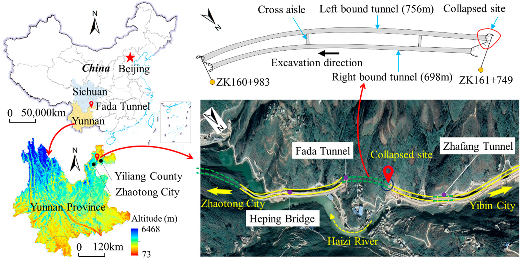
The Fada tunnel in this case study is located in the northeast of Yunnan Province in China, as shown in Figure 1. The tunnel is a part of the Yibin−Zhaotong highway project with a design speed of 80 km/h. The construction of this project began on 30 October 2017. The left bound tunnel is from stake K161 + 739 to K160 + 983, with a total length of 756 m. It connects the Heping Bridge and the Zhafang Tunnel, and the Haizi River is located near this tunnel. The elevation of the tunnel area ranges from 1160 to 1720 m, with an elevation difference of 560 m. It is a tectonically denuded mountainous terrain area with large topographic relief and a natural slope of 20–60°. The tunnel is excavated using the upper and lower bench excavation method, supported by anchor−plate retaining, with a longitudinal slope of 2.5%. the height and the width of the excavated section are 9.59 m and 13.7 m respectively.
2.2. Geological Characteristics
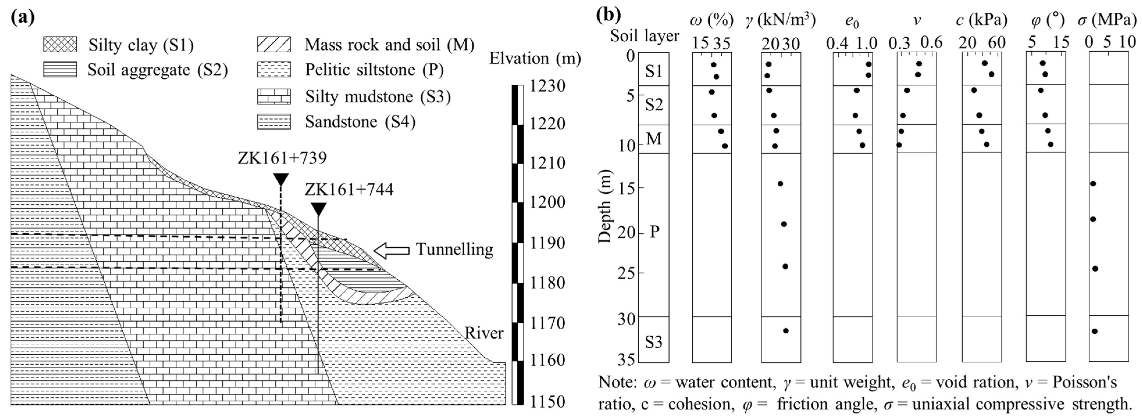
When the tunnel was excavated to 10 m from the tunnel exit, a large−scale tunnel collapse occurred. The geological conditions where the collapse occurred are shown in Figure 2. It can be found that the slope of the tunnel entrance slope is close to 40°. Besides, the entrance slope happens to have a large amount of silty clay with a thickness of 3 m. In summer, due to the washing and erosion of rainfall, debris flows and other geological disasters are prone to occur in this area.
According to the geological survey, the silty clay (S1), soil aggregate (S2), and mass rock and soil (M) all have a high rate of water content, up to 40%. The porosity of each soil layer is also high. As the sandstone at this location is heavily weathered, the uniaxial compressive strength is less than 3 MPa. The mineral composition of the silty clay was obtained by X-ray diffraction test, as shown in Table 1. The main mineral components of red clay at the tunnel site are quartz and kaolinite, accounting for 67%. The mass fraction of montmorillonite is 14%. Moreover, montmorillonite has a greater influence on the water content of soil than other minerals. Therefore, the construction of a tunnel entrance section in rainy season is prone to geological disasters.
2.3. Precipitation
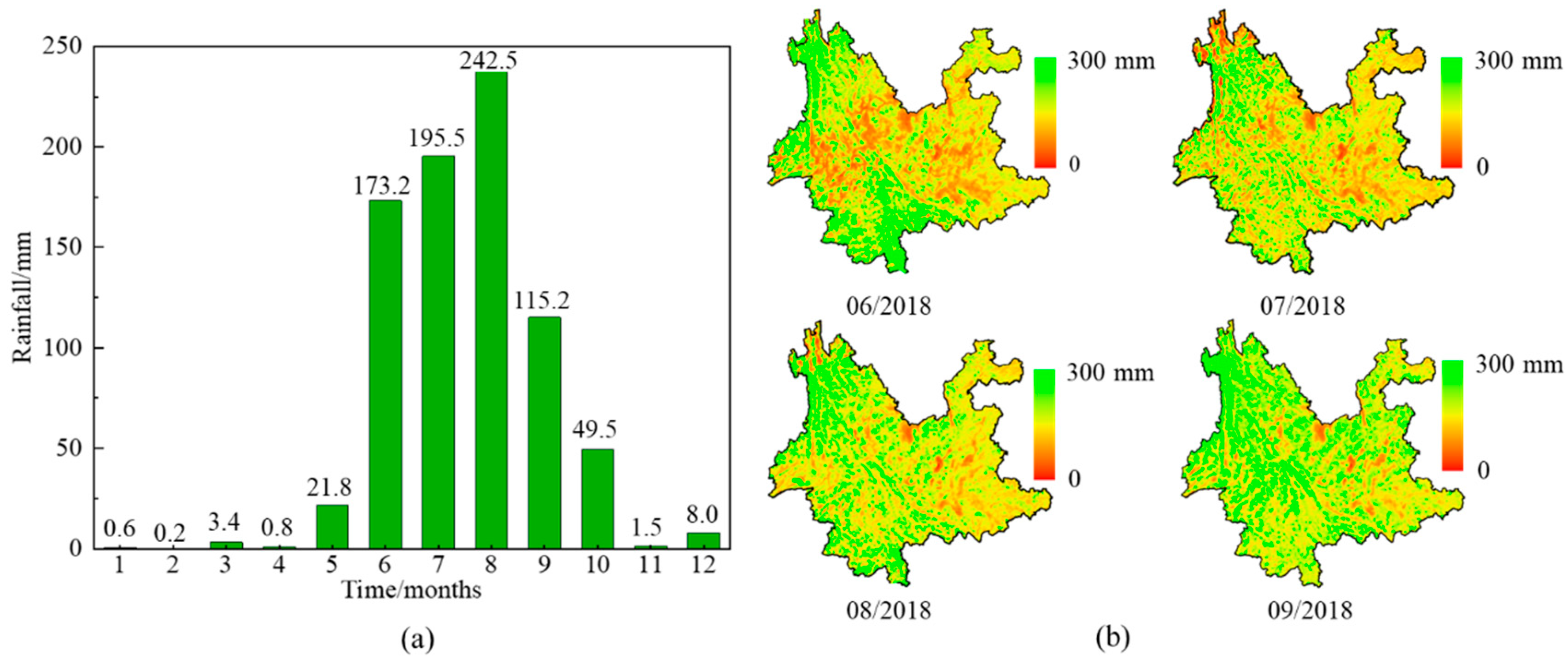
The climate of Zhaotong City, where the tunnel is located, is subtropical monsoonal, with the southeast monsoon from the Pacific Ocean and the southwest monsoon from the Indian Ocean bringing large amounts of rainfall in summer, with an average annual rainfall of 1110 mm. Rainfall throughout the year is mainly concentrated between May and October, accounting for 65.6–91.5% of the total annual rainfall. The uneven seasonal distribution of rainfall results in frequent geological hazards such as landslides and debris flow in the mountainous areas of the region in rainy season. Figure 3 shows the characteristics of the distribution of rainfall in 2018. It can be seen from Figure 3a that the maximum monthly rainfall was 242.5 mm in August, and the rainfall was mainly concentrated from June to September. The distribution of monthly rainfall from June to September in Yunnan Province where the tunnel is located is shown in Figure 3b. It can be seen from the figure that most areas of Yunnan Province have abundant rainfall from June to September. In addition, due to the topographic relief In this region, it is not conducive to the excavation of the mountain tunnel entrance section in summer.
3. Collapse Overview and Failure Mechanisms
3.1. Collapse Overview
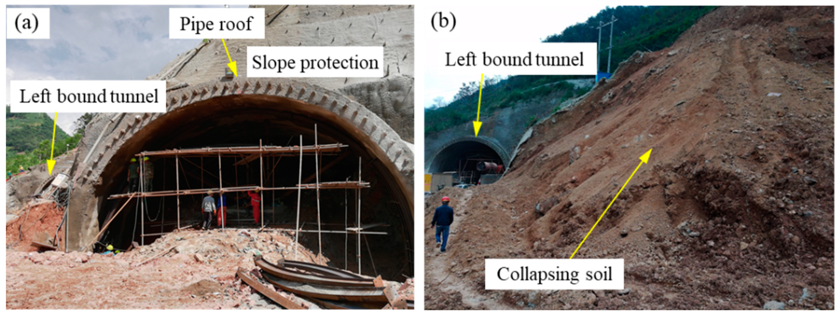
The tunnel site experienced continuous rainfall from 18 to 21 August 2018. On 21 August 2018, when the tunnel face of the left bound tunnel was nearly 10 m away from the tunnel exit, the entrance slope was scoured by continuous heavy rainfall, and a large amount of surface water seeped into the slope. Figure 4a shows a photograph of the tunnel before the collapse. On 22 August, a large−scale tunnel collapse occurred, and the tunnel structure was completely damaged. The tunnel was buried by the collapsing soil above, as shown in Figure 4b. According to the investigation on the collapse site, the length of the collapse landslide along the longitudinal direction of the tunnel was about 27 m, and the collapsing soil was mainly silty clay.
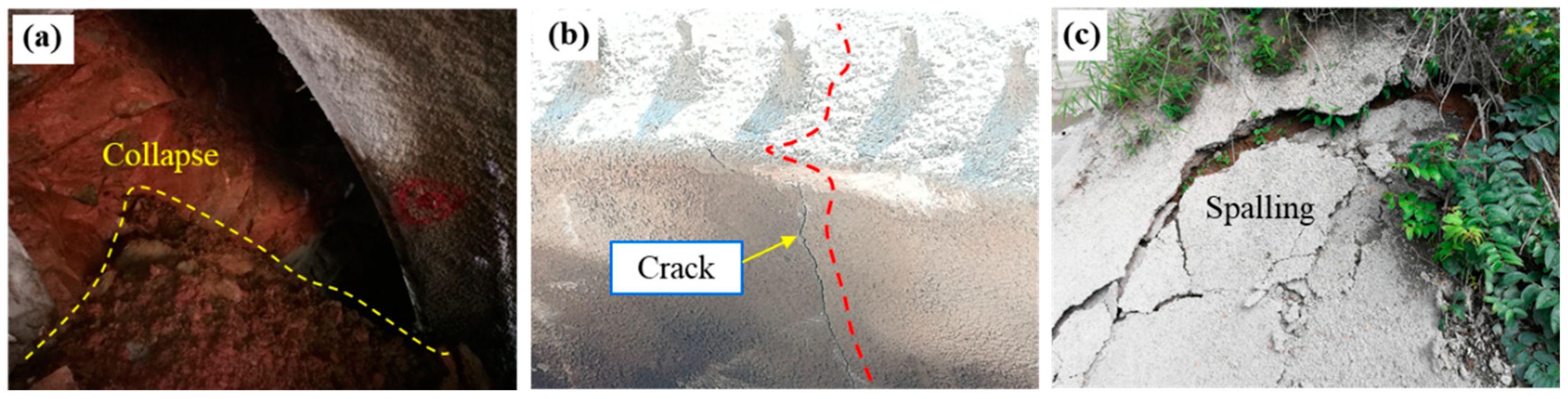
Before the large−scale collapse, many obvious abnormal phenomena appeared in the tunnel site, such as primary support cracking, local collapse of tunnel face, and cracking and spalling of slope protection. However, these abnormal phenomena did not attract the attention of construction personnel.
As the surface water continues to flow into the slope, the soil water content rose rapidly. The shear strength of the soil was also weakened due to the increase of water content, resulting in local collapse of the tunnel face. Figure 5a shows the local collapse on the upper bench of the tunnel face at K161 + 739 before the large−scale collapse. The cracking of initial support concrete also reduced the stability of the tunnel structure during construction. The development of longitudinal cracks indicated that the distribution of surrounding rock pressure had changed, resulting in insufficient bearing capacity of the primary support. Before the large−scale collapse of the left bound tunnel, many cracks appeared on the primary support. The maximum length of longitudinal crack reached 3 m, and the maximum width of crack reached 3 mm. In addition, the concrete of the pipe roof at the tunnel entrance also had longitudinal cracks, with a maximum crack width of 5 mm, as shown in Figure 5b. Before the collapse, the shotcrete on the entrance slope also cracked and spalled in a large range, almost losing its role in preventing the infiltration of surface water, as shown in Figure 5c.
3.2. Collapse Failure Mechanism Analysis
The soil of the tunnel front slope is mainly silty clay. There are many factors that affect the shear strength of silty clay, such as the mineral composition, water content, and density, among which the water content has the most obvious effect on the shear strength parameters of soil. Moreover, the shear strength determines the stability of the soil mass. Therefore, rainfall is the main cause of the collapse. Through the analysis of the abnormal characteristics of the tunnel structure observed on site before the collapse, the main failure mechanism of the accident induced by rainfall can be obtained. Firstly, the excavation of the tunnel caused unloading of the entrance slope, changing the original equilibrium conditions of the slope. Further, unloading caused slight deformation of the slope, resulting in cracks in the shotcrete of the tunnel slope protection. During the continuous rainfall, the surface water continuously scoured the entrance slope, causing the shotcrete cracks of slope protection to expand. As a result, the water content of slope soil was increasing. As the water content of soil increased, the cohesion of soil decreased [47]. Thus, the shear strength of the soil decreased, and the sliding resistance of the slope decreased. At the same time, due to the infiltration of surface water into the slope, the weight of the slope soil increased and the sliding force of the slope increased. During the continuous infiltration of surface water, the shear strength of the clay on the excavation face of the tunnel decreased due to the continuous increased of water content, and local collapse occurred. The abnormal phenomena such as longitudinal cracks of lining observed before the large-scale collapse intuitively show that the stress state of the primary support was changing. Finally, when the strength of the primary support structure of the tunnel was insufficient, excessive deformation occurred under the gravity of the upper soil mass, the stress balance was broken, and the entrance slope of the tunnel also collapse.
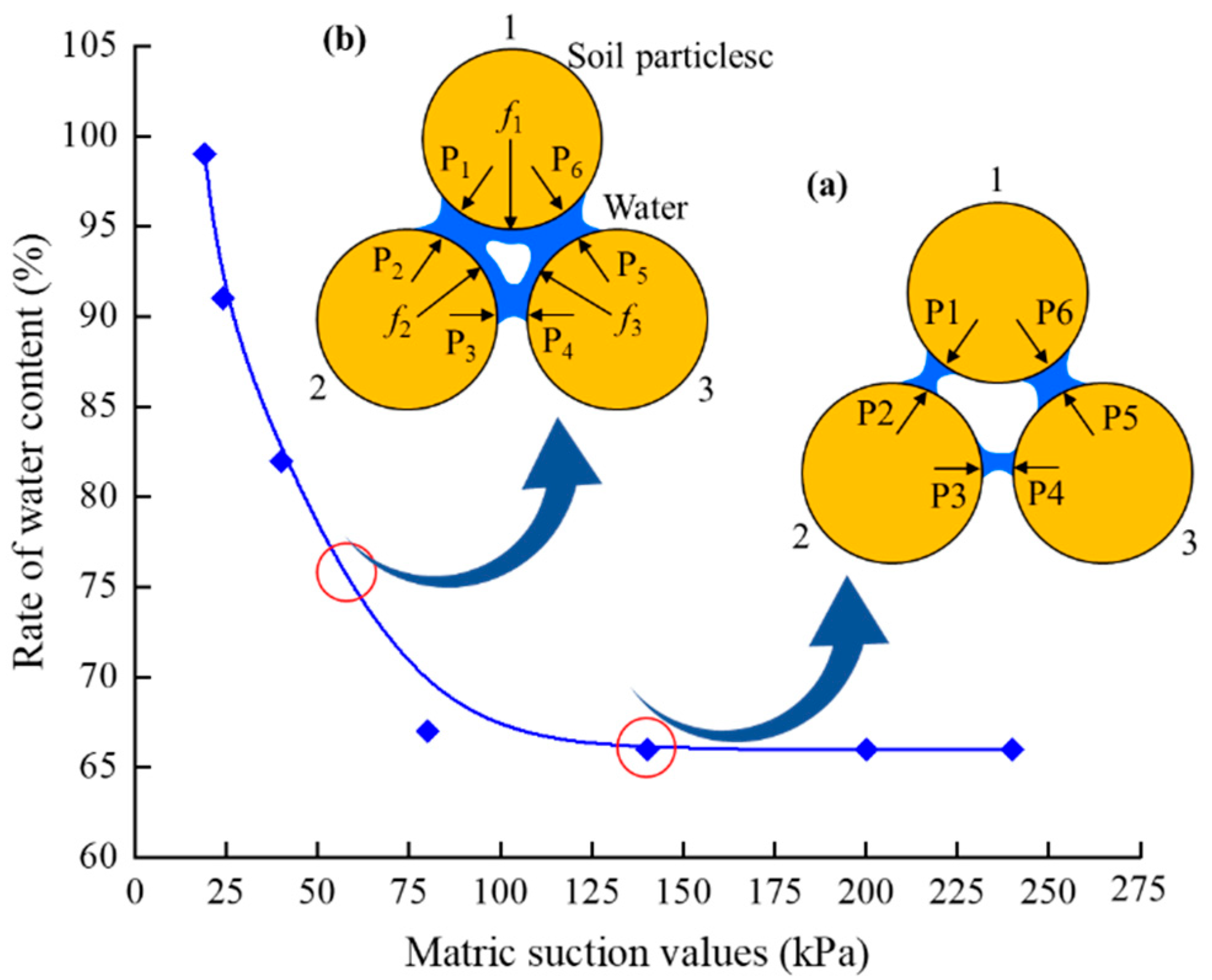
Relevant studies show that the mechanism of the decrease of soil shear strength caused by the increase of water content can be explained by the change of matrix suction between soil particles. The water content directly affects the matrix suction between soil particles. The smaller the water content of clay, the greater the matrix suction and cohesion between soil particles. On the contrary, the greater the water content of clay, the smaller the cohesion. Therefore, the matrix suction decreases with the increase of soil water content, which is an important factor leading to the decline of soil shear strength [48,49]. When the soil changes from unsaturated state to saturated state, the matrix suction between soil particles will gradually decrease to 0. A large number of landslide accidents were induced by the change of soil moisture content, so the matrix suction is closely related to the stability of soil [50].
As shown in Figure 6a, before the rainfall, the soil on the entrance slope of the tunnel was in an unsaturated state with low water content, and all meniscus between soil particles were independent of each other. At this time, the matrix suction between soil particles caused the stress Pi (i = 1, 2, 3, …, 6) that cannot be transferred between soil particles, which inhibited the sliding of soil particles. Because the plastic deformation of soil is interpreted as the sliding between soil particles, the matrix suction resisted the plastic deformation of soil when the soil water content was low. At this water content, the entrance slope was in a good state of stability. When the rainfall started, the water content of the soil mass of the entrance slope gradually increased from the tunnel to the surface [51]. The matrix suction between soil particles also decreased gradually from the tunnel to the surface. Therefore, the shear strength of soil presented the change law of decreasing from the tunnel to the surface. At this time, the soil can be roughly divided into saturated soil and unsaturated soil along the vertical direction. Due to the increasing water content of the unsaturated soil, the unsaturated state between soil particles changes, as shown in Figure 6b. The meniscus in the soil pores was gradually connected. The pressure caused by matrix suction can be transmitted between soil particles, which can cause the compression of soil and reduce the stability of entrance. When the soil mass in a certain depth below the surface of the tunnel entrance slope reached the saturated state, the matrix suction of the soil mass dropped to 0, and this part of the soil mass was prone to sliding.
With the continuous rainfall, the surface water continuously seeped into the entrance slope, resulting in the continuous increase of the water content of the whole tunnel entrance slope, including the soil around the tunnel structure. Therefore, the water content of clay on the tunnel face was also rising, resulting in the decrease of soil shear strength. This then, resulted in local small−scale collapse on the tunnel face, as shown in Figure 5a. The stress state of tunnel support structure was also changed due to rainfall and excavation, which caused abnormal deformation of tunnel primary support, longitudinal cracks. When the surrounding rock pressure exceeded the bearing capacity of the primary support, the tunnel collapsed instantaneously. At the same time, the entrance slope also lost its balance and slid.
3.3. Factors Analysis
There were many factors that led to the tunnel collapse, which can be divided into intrinsic and extrinsic factors. The intrinsic factors were poor geological conditions and structural defects of the tunnel, while the extrinsic factors were rainfall and construction disturbances. A large number of tunnel construction collapse accidents occur during the rainy season, and at the same time, tunnels with collapse accidents during rainfall often have poor geological conditions, such as severe weathering of the surrounding rock, loose internal structure, and easy destruction of the internal structure when exposed to water.
3.3.1. Rainfall
The collapse area belongs to the subtropical monsoon climate, with heavy and concentrated rainfall in summer. Continuous rainfall caused the entrance slope to be continuously washed by surface water, and the water content of the soil rose, leading to hydrogenic softening, and the shear strength of the soil decreased. At the same time, the weight of the soil increased due to the increase of water content, which led to the continuous adjustment of the forces acting on the tunnel lining structure, and the stability of the soil decreased greatly, which was the main reason for the tunnel collapse. In the shallow buried section of the tunnel, the infiltration of surface water into the soil made the water content of the soil near the tunnel lining increase quickly, and the soil reached saturation when the precipitation was large. At this time, the pressure acting on the primary support of the tunnel was not only the gravity of the soil, but also the hydrostatic pressure and seepage forces, resulting in a significant increase in the load on the primary support compared to that before the rainfall. In the primary support strength weak position, the primary support cracking occured, especially the longitudinal cracks were the most harmful [52]. As the soil outside the liner approached saturation, water in the soil leaked into the tunnel along the liner fissures (Figure 5b) and caused erosion of the shotcrete for the primary support. At the location of the tunnel face, if the strength of the shotcrete enclosed on the soil surface of the tunnel face was insufficient, the shear strength of the soil decreased with the increase of water content, which led to a local collapse of the tunnel face (Figure 5a). As surface water continued to seep underground, the pressure on the lining structures increased, and when its bearing capacity was exceeded, the tunnel collapsed instantaneously.
3.3.2. Topography and Geology
The topographical conditions of the tunnel area lead to the decline of the stability of the entrance slope, which has the basic conditions for the collapse disaster.
The location of the collapse in the left bound tunnel was covered with 1–4 m thick powder clay below the surface, which was conducive to the downward seepage of surface water. The clay content of powdered clay was higher compared to the general unsaturated soil, and the clay content was closely related to the size of matrix suction and water storage capacity of the soil. Extensive research found that the higher the clay content, the stronger the water storage capacity, and the water content of silty clay was affected by the increase of clay content, the degree of which first increased and then decreased [53,54]. Therefore, silty clay with high clay content have a higher saturated water content compared to soils with low clay content. Moreover, the physical state and mechanical properties of silty clay are obviously affected by its water content, softening significantly in water, and mechanical parameters such as cohesion and elastic modulus drop significantly, so its water content directly affects the stability and safety of the tunnel [55,56]. When continuous rainfall occurred, the shear strength of the silty clay soil decreased continuously as the water content of the soil rose, and when the water content of the soil was close to saturation, the shear strength of the soil was the lowest and the stability of the entrance slope was the worst. At the same time, the silty clay layer tended to slide along the top surface of the mass rock and stone. The tunnel face of the left bound tunnel passed through the interface between the silty clay layer and the mass rock and soil as well as the sandstone with severe weathering. In the process of continuous downward seepage of surface water, the stability gradually decreased, causing the soil layer to slide along the soil interface.
3.3.3. Unacceptable Construction
The construction of the tunnel entrance section does not meet the requirements of the design, which can lead to a decrease in the stability of the tunnel structure and induce collapse damage to the tunnel. Insufficient primary support strength, untimely support follow−up, and insufficient slope strength are all construction factors that affect the stability of the tunnel [57,58]. The reasons for the insufficient strength of the primary support structure include insufficient thickness and strength of the shotcrete, too large spacing between steel arches, etc. Because the strength of the primary support was insufficient, the shotcrete produced cracks under the pressure in the surrounding rock. Under rainfall conditions, it was also accompanied by water leakage from the lining and erosion of the primary support structure. After tunnel excavation, the surrounding rock stress redistribution occurred. If the support does not follow up in time, it will lead to further expansion of the plastic zone and cause collapse [59]. Besides, the shotcrete of the slope protection was not thick enough and cracks existed, therefore, the surface water continuously seeped down into the slope body, causing the water content of the slope body to rise continuously and the weight of the soil body to increase. A landslide occurred when the sliding force of the slope exceeded the sliding resistance of the slope. Therefore, in areas with high precipitation, improving the quality of slope protection in the tunnel entrance section is one of the effective ways to ensure the safety of the tunnel structure.
4. Countermeasures after Collapse
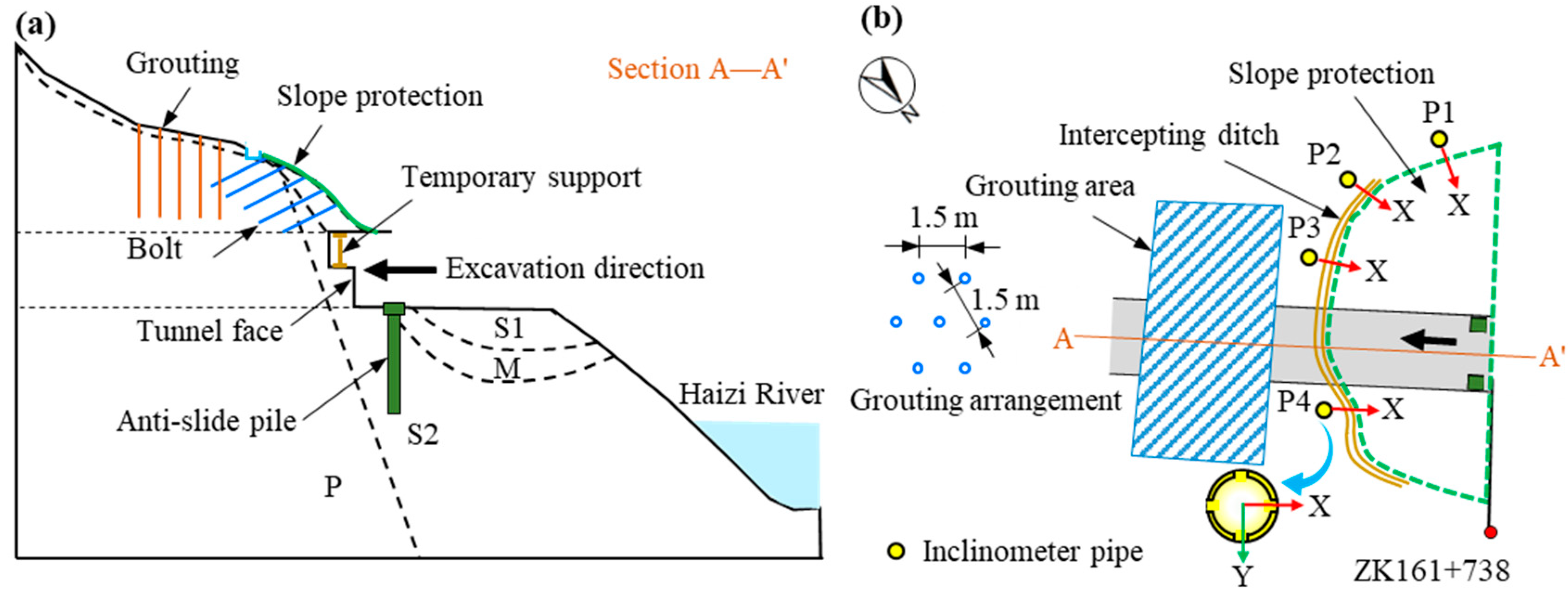
After the collapse occurred, the tunnel was completely buried by the upper sliding soil. Before excavation and removal of the collapsed body, the slope near the collapse that had not experienced a collapse landslide was reinforced. Figure 7 shows the layout of reinforcement measures. The reinforcement measures used for the secondary excavation of the tunnel entrance consisted of three main types: grouting, anti−slide pile, and shotcrete slope protection. Grouting reinforcement mainly includes tunnel surface grouting and grouting in tunnel. Anti−slide piles are set at the tunnel entrance location to reinforce the foundation of the tunnel. At the same time, in order to stop the tunnel from deforming too fast after excavation, leading to cracking of the lining structure, temporary steel supports were installed near the tunnel excavation surface. Four inclinometer pipe were placed on the surface to obtain the deformation data onto the upper slope of the tunnel, and together with the displacement monitoring data onto the tunnel cavity, they were used as the basis of tunnel stability judgment. The direction of the displacement monitoring was the X direction pointed at by the red arrow in Figure 7b.
4.1. Anti−Slide Pile
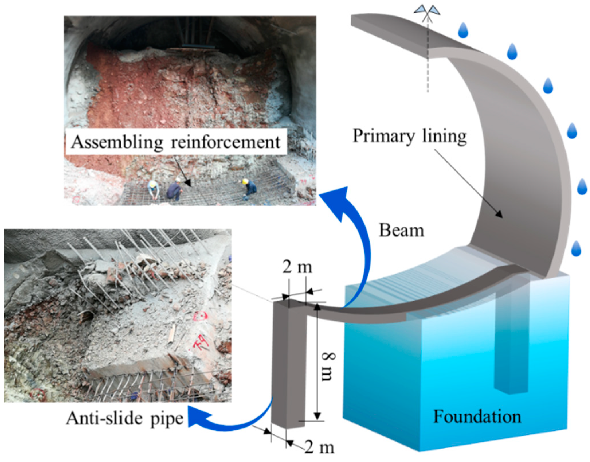
The foundation under the tunnel opening section mainly includes pelitic siltstone and silty mudstone. They were severely weathered, with a large number of fissures, bedded crushing, and low rock strength. In order to prevent the foundation from the tunnel from sliding under the rainfall and to ensure the stability of the tunnel entrance section, the foundation of the tunnel was reinforced by anti−slide piles. The anti−slide piles were set at the arch foot on both sides of the tunnel entrance, with a pile length of 8 m and a rectangular cross−section of 2 × 2 m. Pre−excavated pile holes were excavated on both sides at the arch footing position and the reinforcement cages were placed, then the piles were poured using C20 concrete, as shown in Figure 8. Finally, connecting bars were tied between the two anti−slide piles and concrete was poured to form a concrete beam to connect the two anti−slide piles as a whole and further increase the stability of the foundation.
4.2. Grouting
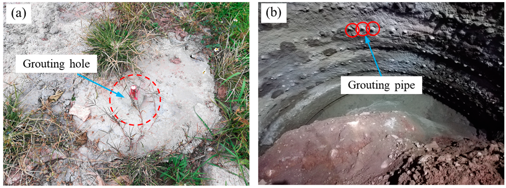
Grouting reinforcement is divided into two parts: surface grouting and grouting in tunnel [60]. Surface grouting reinforcement can not only enhance the integrity of the upper strata of the tunnel, but also form a curtain for cutting off water to stop the downward seepage of surface water and fundamentally cure the problem of slope erosion by surface water. The surface reinforcement grouting holes are shown in Figure 9a. The grouting pipe is made of steel pipe with a diameter of Φ50 mm and pipe thickness of 5 mm. The front part of the grouting pipe was drilled with 8 mm diameter slurry outlets with a spacing of 100 mm. There was no slurry outlet at 500 mm at the end of the grouting pipe. The depth of the surface grouting hole was 5 m. The plane layout of the grouting hole was arranged according to 1.5 × 1.5 m. The slurry for surface grouting used ordinary Portland cement slurry with a water: cement ratio of 1:1, and the initial grouting pressure ranged from 0.5 to 1.0 MPa and the termination pressure ranged from 1.5 to 2.0 MPa. Advance small conduits were used for grouting in the tunnel, with a diameter of 30 mm and a length of 5 m (Figure 9b). The grouting pipes were spaced 500 mm along the tunnel circumferential direction with an external insertion angle of 15 degrees, and the longitudinal lap length of two adjacent rows of grouting pipes was 1 m. The grouting slurry was ordinary cement slurry, and the cement was PO42.5 Portland cement. When the hole was grouted, the initial pressure was 0.2 MPa and the termination pressure was 0.6 MPa.
4.3. Slope Reinforcement
In the entrance section of the tunnel, reducing the seepage of surface water into the tunnel entrance slope is the key to ensuring the stability of the slope. The entrance slope of the tunnel was protected by shotcrete and grouting bolts. Specifically, the grouting bolts were 22 mm in diameter and 4 m in length, arranged in quincunx shape with a spacing of 0.8 m. After the grouting was completed, the reinforcing mesh was laid on the slope surface of the tunnel entrance slope, which was made of a steel bar with a spacing of 0.2 m × 0.2 m. The diameter of the steel bar is 8 mm. After the grouting and reinforcing mesh layout were completed, the tunnel entrance slope was covered with C20 concrete with a thickness of 0.15 m. In order to further reduce the infiltration of surface water into the slope during rainfall, an interceptor ditch was excavated along the outer edge of the slope protection, and surface water flowing to the interceptor ditches was drawn into the interceptor ditch and drained away.
4.4. Analysis on Effects of the Countermeasures
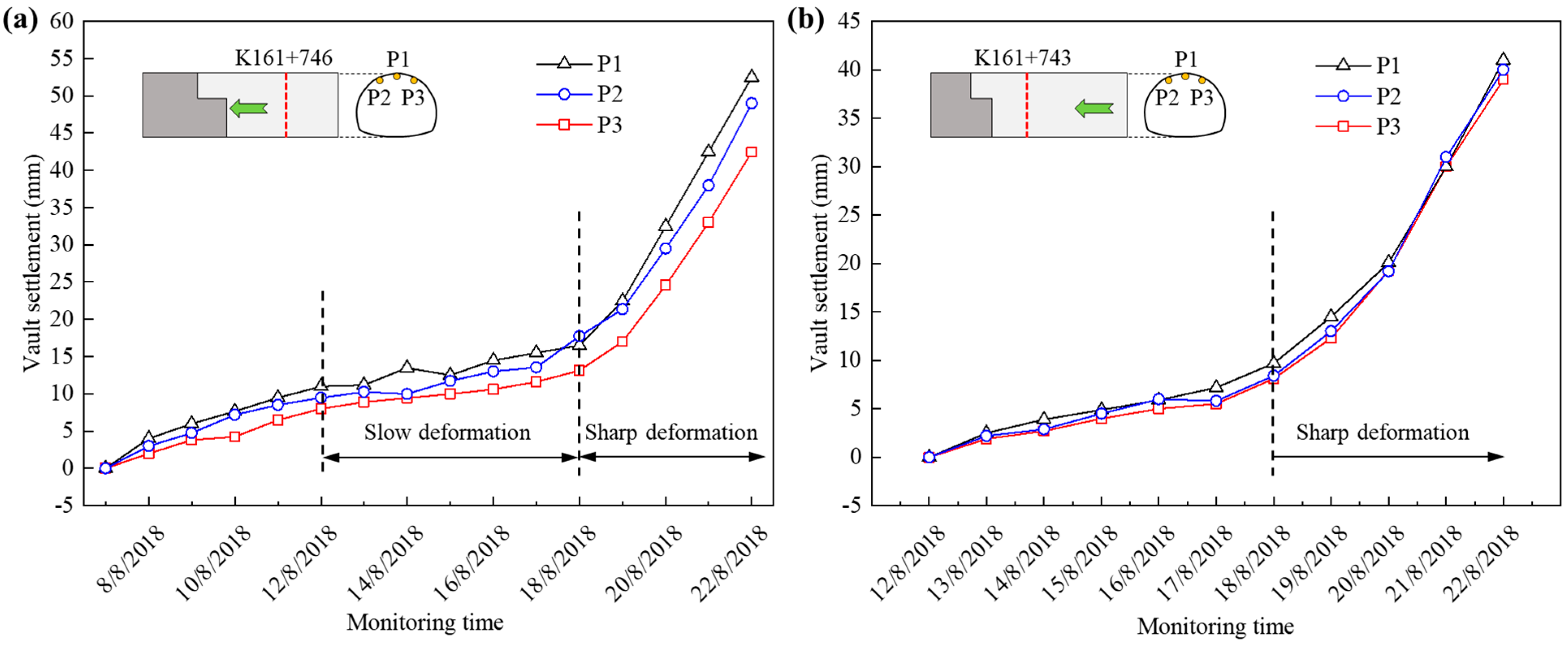
Figure 10 shows the variation curves of vault settlement with the time of two monitoring sections before the tunnel collapse. From the vault settlement monitoring curves of the two monitoring sections in Figure 10, it can be seen that the vault settlement at K161 + 746 started to grow at a significantly slower rate on the 5th day after excavation, indicating that the tunnel surrounding the rock had stabilized at this point. However, from 18 August, the vault settlement increased sharply, and after 4 days before the collapse on 22 August, the average amount of vault settlement was about 48 mm. The vault settlement at K161 + 743 also showed a sudden increase on 18 August. It indicates that the tunnel structure−bearing capacity decreased from this date because of the rainfall.
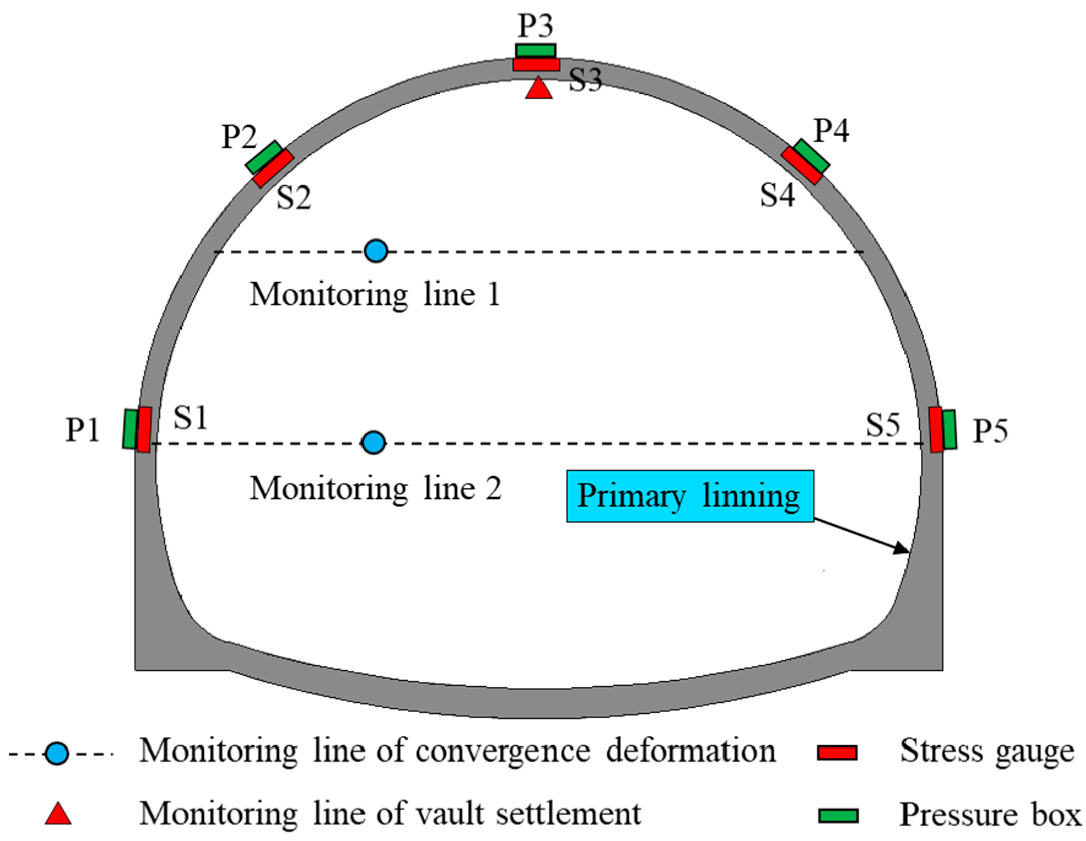
Although the tunnel was reinforced by the above measures, it was in rainy season with frequent rainfall, and there was still the possibility of collapse again. The possible causes of collapse were as follows: (1) The soil at this location still had a high water content after the erosive action of the disturbance that caused this collapse. (2) After the collapse, the soil in the tunnel entrance section became looser than before. (3) The above reinforcement measures were not necessarily the most suitable treatment measures for this collapse and were subject to verification. In order to grasp the displacement changes of surrounding rock during the secondary excavation and the deformation characteristics of the entrance slope, displacement test elements were placed inside the tunnel and inclinometer tubes were installed inside the slope. Inclinometer tubes were laid at the outer edge of the interceptor ditch and inserted vertically downward into the soil layer. The tunnel displacement monitoring data of the monitoring section ZK161 + 729 was selected for reinforcement effect analysis; the test elements and monitoring lines of this section are shown in Figure 11. A total of seven pressure boxes were deployed to monitor the surrounding rock pressure, numbered Pi, i = 1, 2, …, 7. A total of seven stress gauges were laid at the outer edge of the steel arch to measure the size and distribution of the internal forces in the steel arch, numbered Si, i = 1, 2, …, 7. There were three displacement monitoring lines, among which one horizontal convergence monitoring line was laid at the upper and lower step positions.
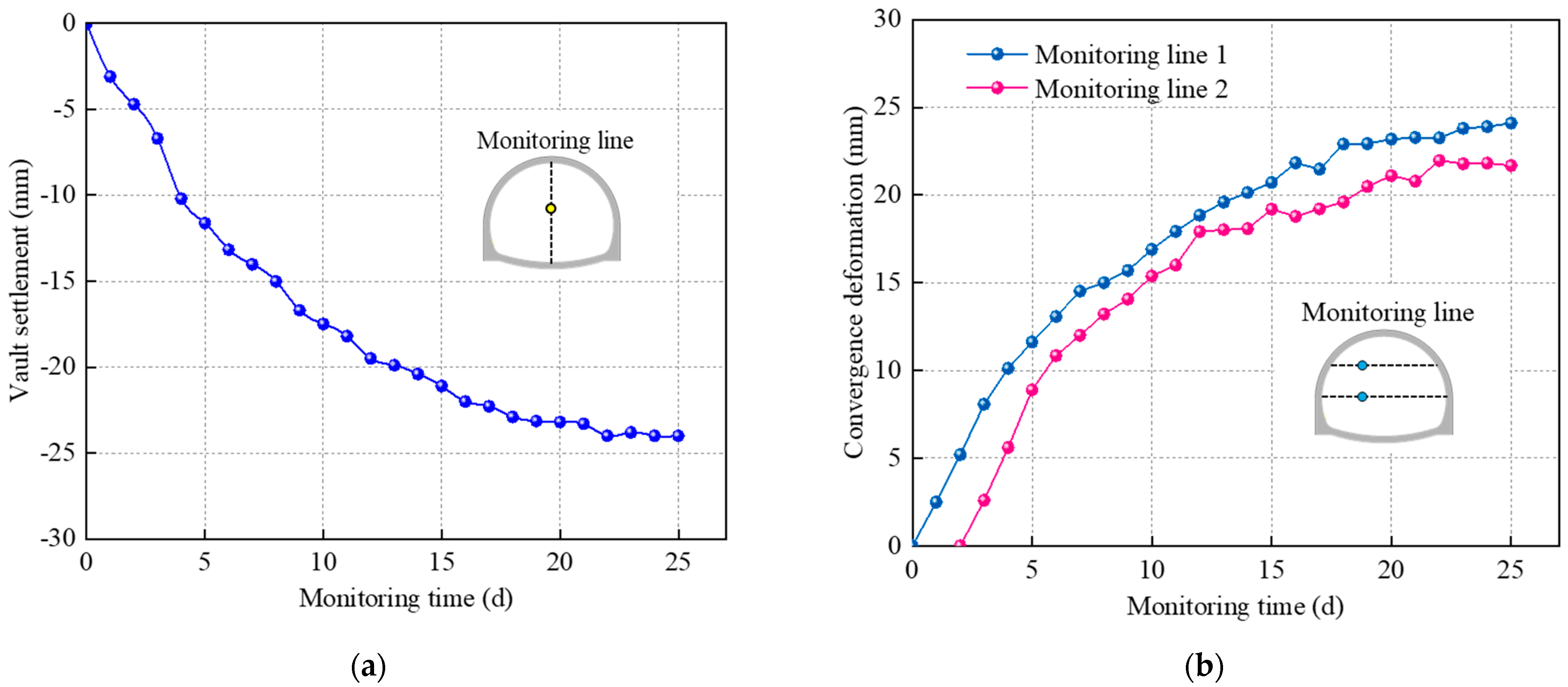
The surrounding rock deformation monitoring curve of ZK161 + 729 is shown in Figure 12. The vault settlement and convergence deformation grew faster in 10 days after the excavation was completed, and gradually slowed down as time increased, and basically stabilized on the 25th day. The stable value of vault settlement was about 24 mm, while stable values of convergence deformation were less than 25 mm. It shows that the tunnel treatment measures played a good role in improving the stability of the entrance slope and tunnel structure during the secondary excavation. Besides, rainfall occurred on the 13th–15th day after the excavation of this section, but the monitoring data found no significant impact on the deformation trend of the tunnel structure, so the surface grouting and slope protection can effectively prevent the infiltration of surface water into the slope.
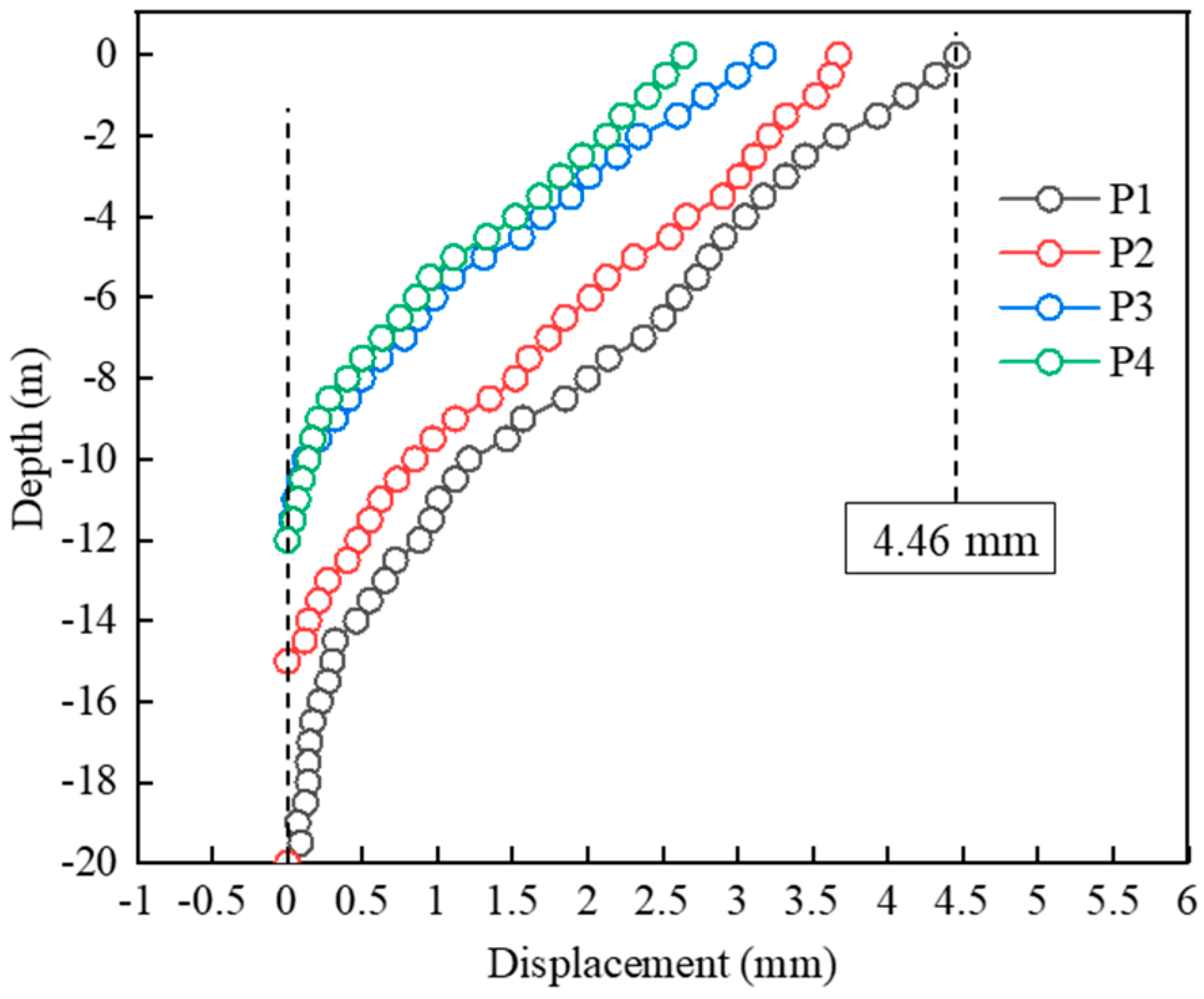
The displacement of soil mass inside the entrance slope can be obtained by using the inclinometer, and then the possible sliding surface and displacement of the slope can be judged. Figure 13 shows the distribution of displacement size of the soil layer at the four inclinometer tubes locations when the monitoring data were stable. At this time, the tunnel was excavated to ZK161 + 712 position. The displacement values of the soil layer at the four monitoring locations were all within 4.46 mm, and the soil layer of the entrance slope did not produce too much displacement. The monitoring results show that the reinforcement measures are effective for the tunnel entrance collapse.
Figure 14 shows the distribution of steel arch stress and surrounding rock pressure at the basic stability of the location of the monitoring section ZK161 + 729. Because the thickness of the upper soil layer of the tunnel at this location was only about 15 m, the steel arch stress and the surrounding rock pressure were not very large. The maximum value of the surrounding rock pressure was 22.3 kPa at the vault, and it shows the distribution feature of “large at the top and small at the bottom”. In general, the pressure on the right side of the tunnel was slightly higher than that on the left side. The steel arch was under pressure at the five monitoring positions, with a maximum stress of 5.954 kN, and the size distribution characteristics were similar to those of the surrounding rock pressure. The steel arch stress and the surrounding rock pressure were within reasonable limits and no abnormalities occurred, which reflected that the tunnel was in a stable state at this location, further demonstrating that the countermeasures were effective in improving the stability of the tunnel structure and entrance slope of the secondary excavation.
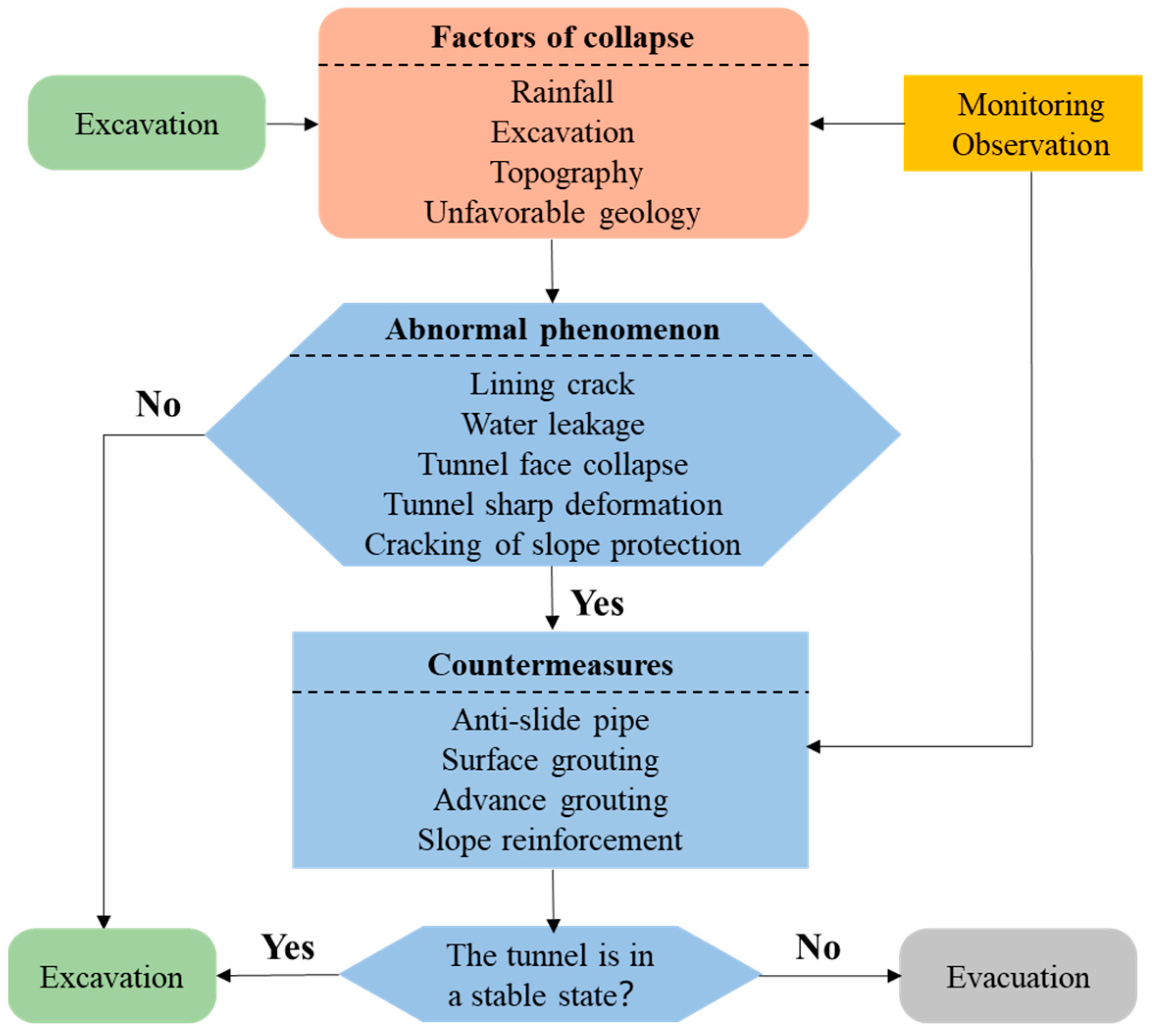
There are many other tunnel construction sites in southwest China with geological and climatic conditions similar to those of the tunnel site in this study. These projects have many commonalities, such as geological conditions, precipitation, and construction methods. Therefore, it is of good application value to summarize the experience of tunnel entrance section collapse in this area and to achieve collapse prevention and effective treatment for similar projects by engineering analogy method. After the study of this accident, an excavation collapse prevention and treatment process applicable to areas with high and concentrated seasonal rainfall and complex geological conditions in the tunnel inlet section is summarized, as shown in Figure 15.
5. Conclusions
This paper analyzed the failure mechanisms and treatment measures of entrance collapse due to sustained rainfall in a highway tunnel as a case study. Also, the characteristics of tunnel before collapse was summed up by field investigation, and the main factors of the collapse were analyzed. Based on the analysis results, treatment measures for tunnel entrance collapse were adopted. Further, the effectiveness of the collapse treatment measures was verified by field monitoring. The main conclusions can be summarized as follows:
- (1)
- In the process of construction at tunnel entrance, rainfall should be emphasized. It reduces the shearing strength of the soil and damages the structure of tunnel, which often causes collapse failures. Other factors including unacceptable construction, topography, and geology also contribute to tunnel entrance collapse. Particularly, improving the quality of slope protection is highly recommended.
- (2)
- The basic causes of the collapse were the infiltration of surface water and the increase of water content of silty clay. The matrix suction decreased with the increase of soil water content, which led to the decline of soil shear strength.
- (3)
- Field investigation showed that abnormal phenomena appeared before large−scale tunnel collapse, such as local collapse of tunnel face, primary support cracking, and shotcrete spalling of slope protection. Timely discovery of abnormal phenomena is of great significance for the prevention of large−scale tunnel collapse accidents. When these phenomena occur on the construction site, it is strongly recommended that the construction personnel evacuate the tunnel immediately.
- (4)
- To prevent a secondary collapse in construction, targeted treatment measures were implemented at this tunnel, such as anti−slide pipe, grouting, and slope reinforcement. Grouting can prevent the seepage of water in soil and improve the stability of surrounding rock. After the collapse treatment was completed, the vault settlement of the monitoring section was only about 24 mm. The countermeasures are effective for collapse at tunnel entrance under rainfall conditions based on the monitoring results and can be applied to similar tunnel entrance slope. Lessons learned from this case provide a reference for the reinforcement of tunnel entrance slope.
Author Contributions
Writing—manuscript, L.-L.C. and Z.-F.W.; methodology, L.-L.C. and Y.-Q.W., data collection, L.-L.C., Y.-Q.W., and Z.-F.W.; case analysis, L.-L.C.; project management, Y.-Q.W. and Z.-F.W.; funding, Z.-F.W. and Y.-Q.W. All authors have read and agreed to the published version of the manuscript.
Funding
The authors gratefully acknowledge the financial support by the National Key R&D Program of China (No. 2021YFB2600404, 2021YFF0501101, 2021YFA0716901 & 2021YFB2601402) and the National Natural Science Foundation of China (No. 51978059 & 52178310).
Institutional Review Board Statement
Not applicable.
Informed Consent Statement
Not applicable.
Data Availability Statement
The data used to support the findings of this study are available from the corresponding author upon request.
Conflicts of Interest
The authors declare no conflict of interest.
References
- Lai, J.; Wang, X.; Qiu, J.; Chen, J.; Hu, Z.; Wang, H. Extreme deformation characteristics and countermeasures for a tunnel in difficult grounds in southern Shaanxi. Environ. Earth Sci. 2018, 77, 706. [Google Scholar] [CrossRef]
- Aberle, J.; Henry, P.Y.; Kleischmann, F.; Navaratnam, C.U.; Vold, M.; Eikenberg, R.; Olsen, N.R.B. Experimental and Numerical Determination of the Head Loss of a Pressure Driven Flow through an Unlined Rock-Blasted Tunnel. Water 2021, 12, 3492. [Google Scholar] [CrossRef]
- Lai, J.; He, S.; Qiu, J.; Chen, J.; Shi, S.; Wang, L.; Wang, K.; Wang, J. Cause analysis of soft and hard rock tunnel collapse and information management. Environ. Earth Sci. 2018, 76, 94. [Google Scholar] [CrossRef]
- Soga, K.; Laver, R.G.; Li, Z.L. Long-term tunnel behaviour and ground movements after tunnelling in clayey soils. Undergr. Space 2018, 2, 149–167. [Google Scholar] [CrossRef]
- Zhang, N.; Zheng, Q.; Elbaz, K.; Xu, Y. Water Inrush Hazards in the Chaoyang Tunnel, Guizhou, China: A Preliminary Investigation. Water 2020, 12, 1083. [Google Scholar] [CrossRef]
- Kim, J.; Kim, C.; Kim, G.; Kim, I.; Abbas, Q.; Lee, J. Probabilistic tunnel collapse risk evaluation model using analytical hierarchy process (AHP) and Delphi survey technique. Tunn. Undergr. Space Technol. 2022, 120, 104262. [Google Scholar] [CrossRef]
- Zheng, X.; Zhang, L.; Wu, S.; Song, K. Study on the Shape of the Aerator of High-Head Discharge Tunnel with Mild Bottom Slope. Water 2021, 13, 2128. [Google Scholar] [CrossRef]
- Farghaly, A.A.; Kontoni, D.P.N. Train induced dynamic response of a pedestrian tunnel under a four-track surface railway for different soil water contents. Geomech. Eng. 2019, 16, 341–353. [Google Scholar] [CrossRef]
- Gattinoni, P.; Consonni, M.; Francani, V.; Leonelli, G.; Lorenzo, C. Tunnelling in landslide areas connected to deep seated gravitational deformations: An example in Central Alps (northern Italy). Tunn. Undergr. Space Technol. 2019, 93, 103100. [Google Scholar] [CrossRef]
- Xue, Y.; Zhang, S.; Zhou, M.; Zhu, H. Novel SfM-DLT method for metro tunnel 3D reconstruction and visualization. Undergr. Space 2021, 6, 134–141. [Google Scholar] [CrossRef]
- Guo, C.; Guo, Q.; Zhang, T.; Li, W.; Zhu, H.; Yan, Z. Study on real-time heat release rate inversion for dynamic reconstruction and visualization of tunnel fire scenarios. Tunn. Undergr. Space Technol. 2022, 122, 104333. [Google Scholar] [CrossRef]
- Fraldi, M.; Guarracino, F. Analytical solutions for collapse mechanisms in tunnels with arbitrary cross sections. Int. J. Solids Struct. 2010, 47, 216–223. [Google Scholar] [CrossRef]
- Sun, W.; Liang, Q.; Qin, S.; Yuan, Y.; Zhang, T. Evaluation of groundwater effects on tunnel engineering in loess. Bull. Eng. Geol. Environ. 2021, 80, 1947–1962. [Google Scholar] [CrossRef]
- Wang, J.; Lin, G.; Xu, G.; Wei, Y.; Li, S.; Tang, X.; He, C. Face stability of EPB shield tunnels in multilayered ground with soft sand lying on hard rock considering dynamic excavation process: A DEM study. Tunn. Undergr. Space Technol. 2022, 120, 104268. [Google Scholar] [CrossRef]
- Prendes-Gero, M.B.; Lopez-Gayarre, F.; Menendez-Fernandez, C.; Llardent, M.R.A. Forensic analysis of the failure of the foundations of a tunnel built to channel the course of a river. Eng. Fail. Anal. 2013, 32, 152–166. [Google Scholar] [CrossRef]
- Xu, Z.; Cai, N.; Li, X.; Xian, M.; Dong, T. Risk assessment of loess tunnel collapse during construction based on an attribute recognition model. Bull. Eng. Geol. Environ. 2021, 80, 6205–6220. [Google Scholar] [CrossRef]
- Wu, B.; Qiu, W.; Huang, W.; Meng, G.; Huang, J.; Xu, S. Dynamic risk evaluation method for collapse disasters of drill-and-blast tunnels: A case study. Math. Biosci. Eng. 2021, 19, 309–330. [Google Scholar] [CrossRef]
- Han, K.; Ju, J.W.W.; Kong, H.; Wang, M. Functional catastrophe analysis of progressive failures for deep tunnel roof considering variable dilatancy angle and detaching velocity. Rock Mech. Rock Eng. 2019, 52, 3987–3997. [Google Scholar] [CrossRef]
- Zhang, C.; Han, K. Collapsed shape of shallow unlined tunnels based on functional catastrophe theory. Math. Probl. Eng. 2015, 2015, 681257. [Google Scholar] [CrossRef]
- Ma, E.; Lai, J.; Xu, S.; Shi, S.; Zhang, J.; Zhong, Y. Failure analysis and treatments of a loess tunnel being constructed in ground fissure area. Eng. Fail. Anal. 2022, 134, 106034. [Google Scholar] [CrossRef]
- Xu, S.; Lei, H.; Li, C.; Liu, H.; Lai, J.; Liu, T. Model test on mechanical characteristics of shallow tunnel excavation failure in gully topography. Eng. Fail. Anal. 2020, 119, 104978. [Google Scholar] [CrossRef]
- Yu, L.; Zhang, D.; Fang, Q.; Cao, L.; Zhang, Y.; Xu, T. Face stability of shallow tunnelling in sandy soil considering unsupported length. Tunn. Undergr. Space Technol. 2020, 102, 103445. [Google Scholar] [CrossRef]
- Hu, X.; Fu, W.; Wu, S.; Fang, Y.; Wang, J.; He, C. Numerical study on the tunnel stability in granular soil using DEM virtual air bag model. Acta Geotech. 2021, 16, 3285–3300. [Google Scholar] [CrossRef]
- Wu, Y.; Wang, K.; Zhang, L.; Peng, S. Sand-layer collapse treatment: An engineering example from Qingdao Metro subway tunnel. J. Clean Prod. 2018, 197, 19–24. [Google Scholar] [CrossRef]
- Xu, H.; Shao, Z.; Chen, C.; Wang, Z.; Cai, L.; Li, Z.; Huang, C. Characteristics and evolution of tunnel collapse in fully-weathered coastal red sandstone strata. J. Coast. Res. 2022, 38, 289–301. [Google Scholar] [CrossRef]
- Xu, H.; Wang, Z.; Chen, C.; Cai, L.; Li, Z.; Deng, Y.; Xia, Y. Model tests on characteristics and evolution of tunnel collapse in soil-sand interbedded strata. Chin. J. Geotech. Eng. 2021, 43, 1050–1058. (In Chinese) [Google Scholar]
- Wang, Z.; Xie, Y.; Lai, J.; Xie, Y.; Su, X.; Shi, Y.; Guo, C. Designing an innovative support system in loess tunnel. Geomech. Eng. 2021, 24, 253–266. [Google Scholar] [CrossRef]
- Senent, S.; Jimenez, R. A tunnel face failure mechanism for layered ground, considering the possibility of partial collapse. Tunn. Undergr. Space Technol. 2015, 47, 182–192. [Google Scholar] [CrossRef]
- Wang, B.; Li, T.; HE, C.; Zhou, Y. Analysis of failure properties and formatting mechanism of soft rock tunnel in meizoseismal areas. Chin. J. Rock Mech. Eng. 2012, 31, 928–936. (In Chinese) [Google Scholar]
- Toulkeridis, T.; Rodriguez, F.; Jimenez, N.A.; Baile, D.S.; Martinez, R.S.; Addison, A.; Freyre, D.C.; Mato, F.; Perez, C.D. Causes and consequences of the sinkhole at El Trebol of Quito, Ecuador-implications for economic damage and risk assessment. Nat. Hazards Earth Syst. Sci. 2016, 16, 2031–2041. [Google Scholar] [CrossRef]
- Liu, X.; Liu, F.; Song, K. Mechanism analysis of tunnel collapse in a soft-hard interbedded surrounding rock mass: A case study of the Yangshan Tunnel in China. Eng. Fail. Anal. 2022, 138, 106304. [Google Scholar] [CrossRef]
- Wang, Y. Collapse mechanism and preventive measures of mountain tunnel. Chin. J. Rock Mech. Eng. 2012, 30, 2376. (In Chinese) [Google Scholar]
- Wang, Z.; Shen, S.; Modoni, G.; Zhou, A. Excess pore water pressure caused by the installation of jet grouting columns in clay. Comput. Geotech. 2020, 125, 103667. [Google Scholar] [CrossRef]
- Jiang, Z.; Duan, S.; Zhao, X. Manipulation of tunnelling in a quantum dot array. J. Phys.-Condes. Matter 2005, 17, 4207–4222. [Google Scholar] [CrossRef]
- Niu, J.; Sun, Y.; Wang, B.; Zhang, K.; Huang, Y.; Huang, S.; Yu, J.; Qiu, L. Grouting Treatment of Water and Mud Inrush in Fully Weathered Granite Tunnel: A Case Study. Disaster Adv. 2020, 2020, 8838769. [Google Scholar] [CrossRef]
- Zhang, T.; Taylor, R.N.; Zheng, G.; Sun, J.; Fan, Q.; Diao, Y.; Zhou, H. Modelling ground movements near a pressurised tunnel heading in drained granular soil. Comput. Geotech. 2018, 104, 152–166. [Google Scholar] [CrossRef]
- Wu, D.; Deng, T.; Zhao, R.; Wang, Y. THM modeling of ground subsidence induced by excavation of subway tunnel. Comput. Geotech. 2018, 94, 1–11. [Google Scholar] [CrossRef]
- Wang, Z.; Cheng, W. Predicting jet-grout column diameter to mitigate the environmental impact using an artificial intelligence algorithm. Undergr. Space. 2021, 6, 267–280. [Google Scholar] [CrossRef]
- Yang, Z.; Wu, S.; Gao, Y.; Jin, A.; Cong, Z. Time and technique of rehabilitation for large deformation of tunnels in jointed rock masses based on FDM and DEM numerical modeling. Tunn. Undergr. Space Technol. 2018, 81, 669–681. [Google Scholar] [CrossRef]
- Yuan, J.; Chen, W.; Tan, X.; Yang, D.; Wang, S. Countermeasures of water and mud inrush disaster in completely weathered granite tunnels: A case study. Environ. Earth Sci. 2019, 78, 576. [Google Scholar] [CrossRef]
- Zhang, N.; Shen, J.; Lin, C.; Arulrajah, A.; Chai, J. Investigation of a large ground collapse and countermeasures during mountain tunnelling in Hangzhou: A case study. Bull. Eng. Geol. Environ. 2019, 78, 991–1003. [Google Scholar] [CrossRef]
- Zheng, G.; Cui, T.; Cheng, X.; Diao, Y.; Zhang, T.; Sun, J.; Ge, L. Study of the collapse mechanism of shield tunnels due to the failure of segments in sandy ground. Eng. Fail. Anal. 2017, 79, 464–490. [Google Scholar] [CrossRef]
- Zheng, H.; Li, P.; Ma, G.; Zhang, Q. Experimental investigation of mechanical characteristics for linings of twins tunnels with asymmetric cross-section. Tunn. Undergr. Space Technol. 2021, 119, 104209. [Google Scholar] [CrossRef]
- Qiu, J.; Wang, X.; Lai, J.; Zhang, Q.; Wang, J. Response characteristics and preventions for seismic subsidence of loess in Northwest China. Nat. Hazards 2018, 98, 1909–1935. [Google Scholar] [CrossRef]
- Wang, Z.; Shen, S.; Modoni, G. Enhancing discharge of spoil to mitigate disturbance induced by horizontal jet grouting in clayey soil: Theoretical model and application. Comput. Geotech. 2019, 111, 222–228. [Google Scholar] [CrossRef]
- Koyama, T.; Nishiyama, S.; Yang, M.; Ohnishi, Y. Modeling the interaction between fluid flow and particle movement with discontinuous deformation analysis (DDA) method. Int. J. Numer. Anal. Methods Geomech. 2011, 35, 1–20. [Google Scholar] [CrossRef]
- Yang, Q.; He, J.; Luan, M. Comparative study on shear strength of unsaturated red clay and expansive soils. Rock Soil Mech. 2003, 24, 13–16. (In Chinese) [Google Scholar]
- Shiau, J.; Al-Asadi, F. Revisiting circular tunnel stability using Broms and Bennermarks’ original stability number. Int. J. Geomech. 2021, 21, 06021009. [Google Scholar] [CrossRef]
- Cho, S.E. Stability analysis of unsaturated soil slopes considering water-air flow caused by rainfall infiltration. Eng. Geol. 2016, 211, 184–197. [Google Scholar] [CrossRef]
- Lin, H.; Li, G.; Yu, Y.; Lu, H. Influence of matric suction on shear strength behavior of unsaturated soils. Rock Soil Mech. 2007, 28, 1931–1936. (In Chinese) [Google Scholar]
- Mahmood, K.; Kim, J.M.; Khan, H.; Safdar, M.; Khan, U. The probabilistic stability analysis of saturated-unsaturated MH and CL soil slope with rainfall infiltration. KSCE J. Civ. Eng. 2018, 22, 1742–1749. [Google Scholar] [CrossRef]
- Lan, W.; Deng, X.; Sutton, M.A. Investigation of crack tunneling in ductile materials. Eng. Fract. Mech. 2010, 77, 2800–2812. [Google Scholar] [CrossRef]
- Stark, T.D.; Jafari, N.H.; Zhindon, J.S.L.; Baghdady, A. Unsaturated and Transient Seepage Analysis of San Luis Dam. J. Geotech. Geoenviron. Eng. 2017, 14, 04016093. [Google Scholar] [CrossRef]
- Zhang, Y.; Pu, S.; Li, R.T.Y.M.; Zhang, J. Microscopic and mechanical properties of undistributed and remoulded red clay from Guiyang, China. Sci. Rep. 2021, 10, 18003. [Google Scholar] [CrossRef] [PubMed]
- Lu, C.; Qin, W.; Zhao, G.; Zhang, Y.; Wang, W. Better-Fitted Probability of Hydraulic Conductivity for a Silty Clay Site and Its Effects on Solute Transport. Water 2017, 9, 466. [Google Scholar] [CrossRef]
- John, D.; Jaye, C.; Robert, L.; Kemp, G.P. Sediment Deposition at the Caernarvon Crevasse during the Great Mississippi Flood of 1927: Implications for Coastal Restoration. Water 2016, 8, 38. [Google Scholar] [CrossRef]
- Zhang, W.; Cai, F.; Zhou, J.; Hua, Y. Experimental Investigation on Air-Water Interaction in a Hydropower Station Combining a Diversion Tunnel with a Tailrace Tunnel. Water. Stud. 2019, 9, 274. [Google Scholar] [CrossRef]
- Xue, Y.; Li, X.; Li, G.; Qiu, D.; Gong, H.; Kong, F. An analytical model for assessing soft rock tunnel collapse risk and its engineering application. Geomech. Eng. 2020, 23, 441–454. [Google Scholar] [CrossRef]
- Huang, F.; Zhao, L.; Ling, T.; Yang, X. Rock mass collapse mechanism of concealed karst cave beneath deep tunnel. Int. J. Rock Mech. Min. Sci. 2017, 91, 133–138. [Google Scholar] [CrossRef]
- Niu, F.; Cai, Y.; Liao, H.; Li, J.; Tang, K.; Wang, Q.; Wang, Z.; Liu, D.; Liu, T.; Liu, C. Unfavorable Geology and Mitigation Measures for Water Inrush Hazard during Subsea Tunnel Construction: A Global Review. Water 2022, 14, 1592. [Google Scholar] [CrossRef]
Figure 1.
Location of the tunnel.

Figure 2.
Geological conditions. (a) Strata at the collapsed site; (b) measured soil parameter profiles.
Figure 2.
Geological conditions. (a) Strata at the collapsed site; (b) measured soil parameter profiles.

Figure 3.
Rainfall description in 2018: (a) monthly rainfall of Zhaotong City (https://www.qweather.com/historical/zhaotong-101291001.html, accessed on 5 June 2022); (b) rainfall distribution in Yunnan Province (http://www.geodata.cn, accessed on 5 June 2022).
Figure 3.
Rainfall description in 2018: (a) monthly rainfall of Zhaotong City (https://www.qweather.com/historical/zhaotong-101291001.html, accessed on 5 June 2022); (b) rainfall distribution in Yunnan Province (http://www.geodata.cn, accessed on 5 June 2022).

Figure 4.
Photographs of the tunnel: (a) before collapse; (b) after collapse.

Figure 5.
Phenomena before collapse: (a) local collapse of tunnel face; (b) lining cracking; (c) shotcrete spalling.
Figure 5.
Phenomena before collapse: (a) local collapse of tunnel face; (b) lining cracking; (c) shotcrete spalling.

Figure 6.
The relationships between rate of water content and matric suction of silty clay [50]. (a) low water content; (b) high water content.
Figure 6.
The relationships between rate of water content and matric suction of silty clay [50]. (a) low water content; (b) high water content.

Figure 7.
Layout of treatment measures. (a) Vertical section; (b) vertical view.

Figure 8.
Anti−slide pile.

Figure 9.
Photographs of grouting. (a) Surface grouting; (b) grouting in tunnel.

Figure 10.
Vault settlement before collapse: (a) K161 + 746 section; (b) K161 + 743 section.

Figure 11.
Layout and photographs of test elements at ZK161 + 729.

Figure 12.
Displacement monitoring curve of primary lining. (a) variation curve of vault settlement; (b) variation curve of convergence deformation.
Figure 12.
Displacement monitoring curve of primary lining. (a) variation curve of vault settlement; (b) variation curve of convergence deformation.

Figure 13.
Variation curve of horizontal displacement at various depths.

Figure 14.
Stress monitoring results: (a) surrounding rock pressure; (b) steel arch stress.

Figure 15.
Prevention and treatment process of tunnel entrance collapse under rainfall condition.


Table 1.
The mineral composition of the silty clay.
| Mineral Name | Quartz | Gibbsite | Kaolinite | Illite | Montmorillonite | Goethite | Anatase |
|---|---|---|---|---|---|---|---|
| Mass fraction (%) | 27 | 9 | 6 | 40 | 14 | 3 | 1 |
Publisher’s Note: MDPI stays neutral with regard to jurisdictional claims in published maps and institutional affiliations. |
© 2022 by the authors. Licensee MDPI, Basel, Switzerland. This article is an open access article distributed under the terms and conditions of the Creative Commons Attribution (CC BY) license (https://creativecommons.org/licenses/by/4.0/).
Share and Cite
MDPI and ACS Style
Chen, L.-L.; Wang, Z.-F.; Wang, Y.-Q. Failure Analysis and Treatments of Tunnel Entrance Collapse Due to Sustained Rainfall: A Case Study. Water 2022, 14, 2486. https://doi.org/10.3390/w14162486
AMA Style
Chen L-L, Wang Z-F, Wang Y-Q. Failure Analysis and Treatments of Tunnel Entrance Collapse Due to Sustained Rainfall: A Case Study. Water. 2022; 14(16):2486. https://doi.org/10.3390/w14162486
Chicago/Turabian StyleChen, Long-Long, Zhi-Feng Wang, and Ya-Qiong Wang. 2022. "Failure Analysis and Treatments of Tunnel Entrance Collapse Due to Sustained Rainfall: A Case Study" Water 14, no. 16: 2486. https://doi.org/10.3390/w14162486
Note that from the first issue of 2016, this journal uses article numbers instead of page numbers. See further details here.