
Concerning Dynamic Effects in Pipe Systems with Two-Phase Flows: Pressure Surges, Cavitation, and Ventilation

 ,
,  , , ,
, , ,  , and
, and 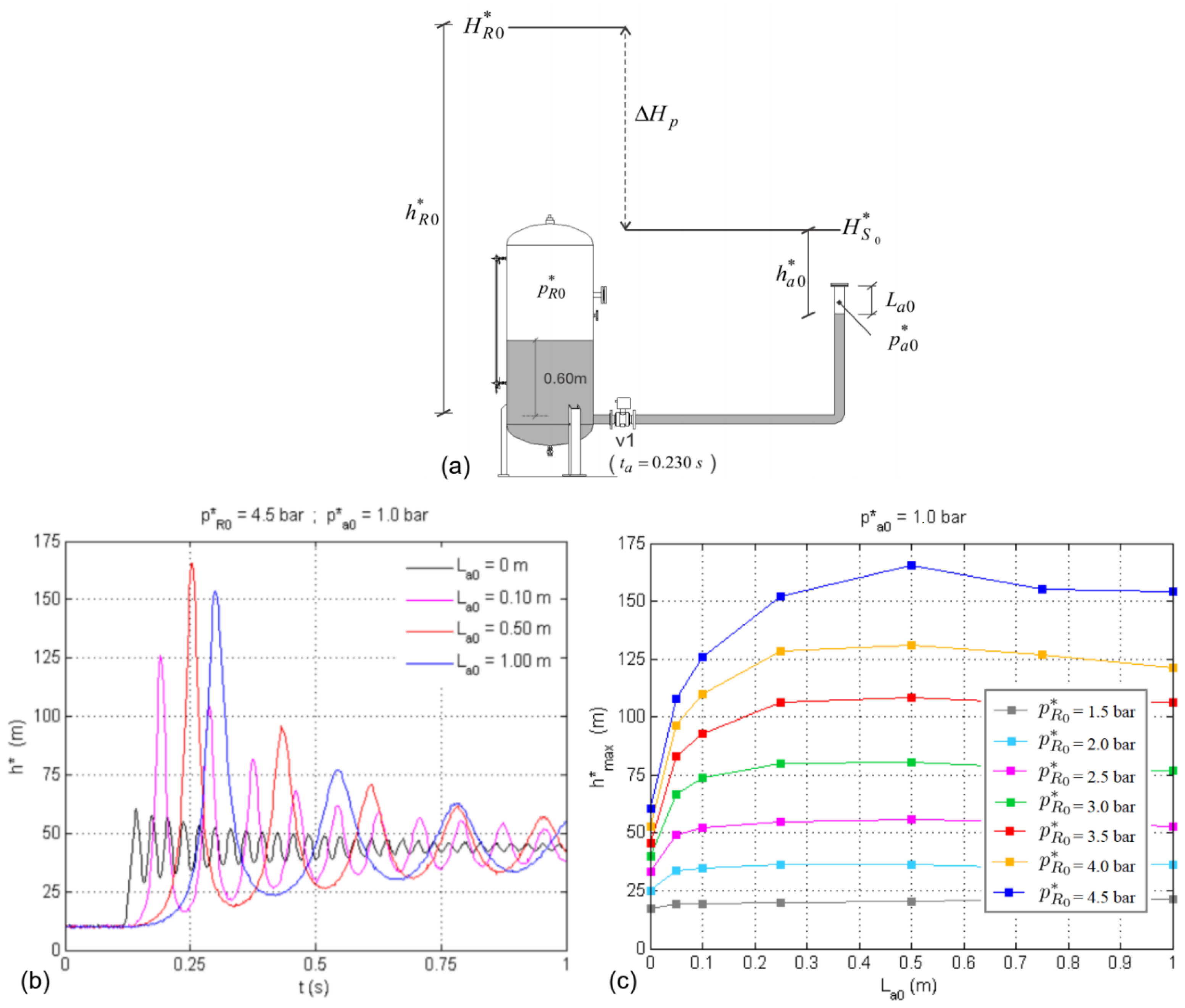
Abstract
:1. Introduction
2. Two-Phase Flows in Pressurized Systems
2.1. Pipeline Filling Operations
2.1.1. Confined System
2.1.2. Ventilated System
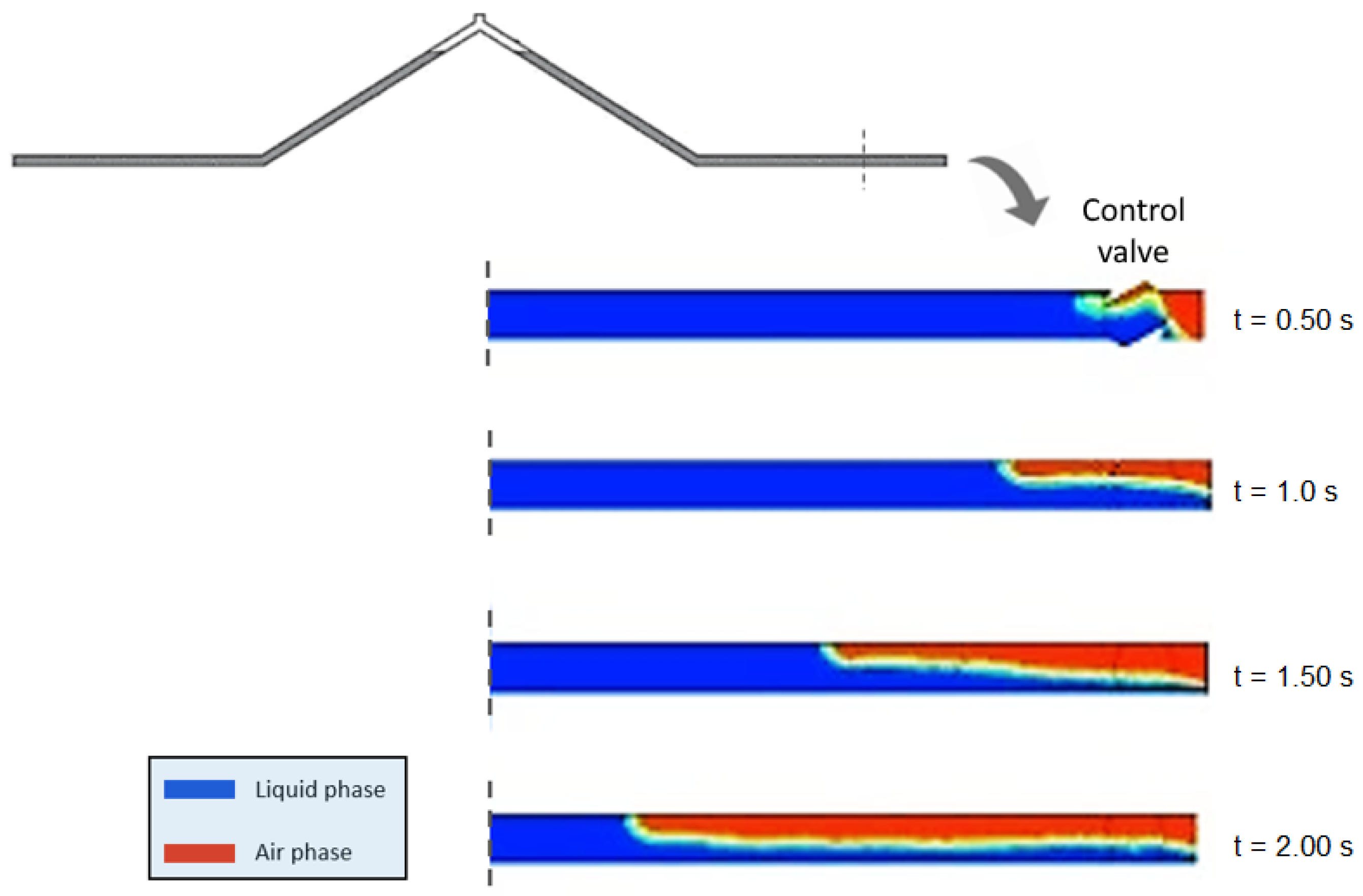
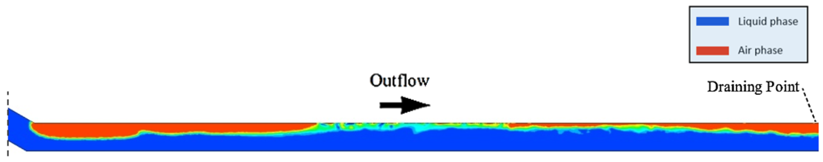
2.2. Pipeline Draining Operations
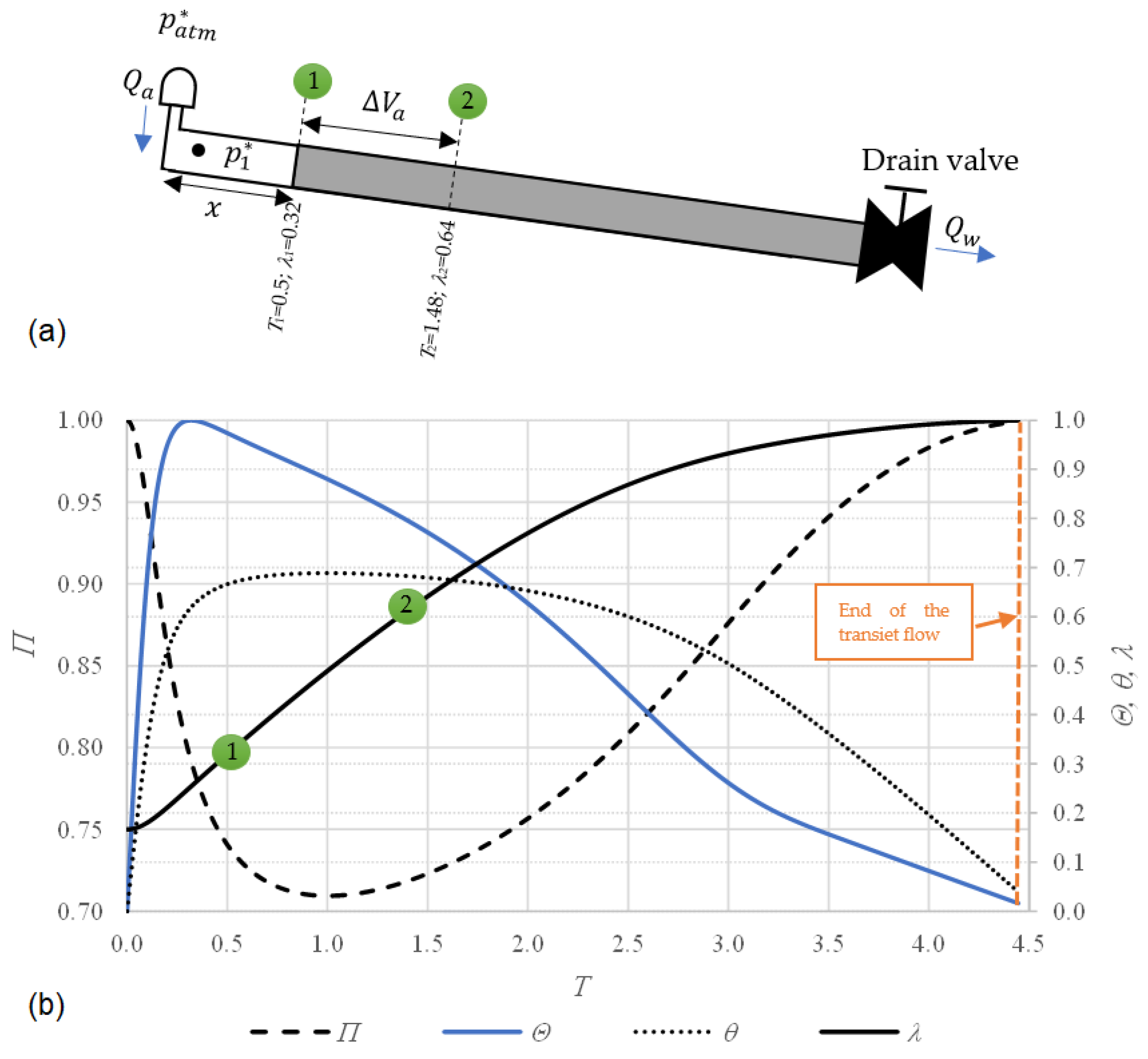
2.2.1. Progression of Hydraulic and Thermodynamic Variables
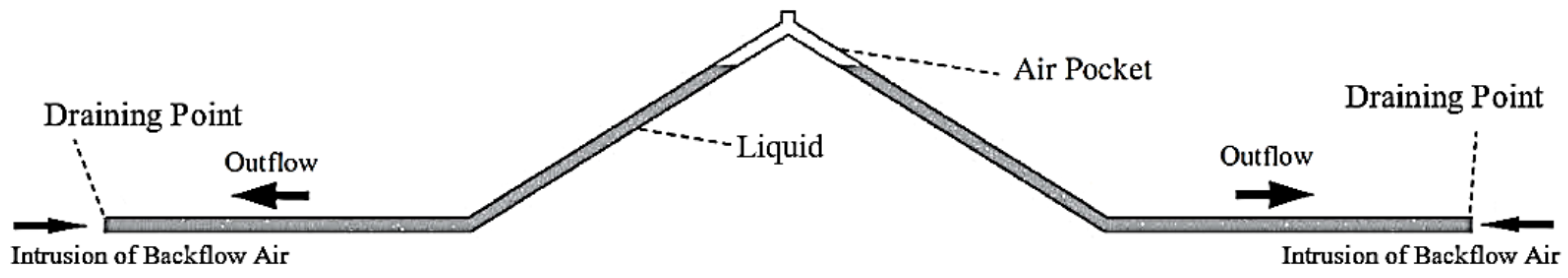
2.2.2. Backflow Air Intrusion
3. Air Valves for Air Management in Pressurized Lines
3.1. Intake and Expulsion of Air
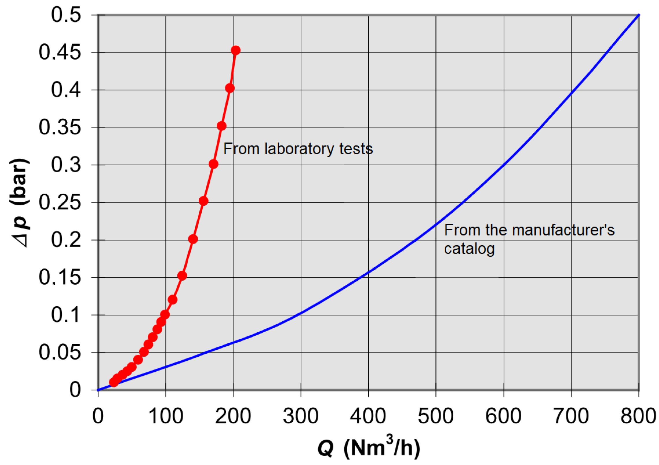
3.2. Characteristic Curves of Air Valves
3.3. The Use of the M51 Manual for Air Valve Application
4. Macro-Cavitation and Air Exchanges through Air Valves during Unsteady Flows
5. Discussion
6. Conclusions
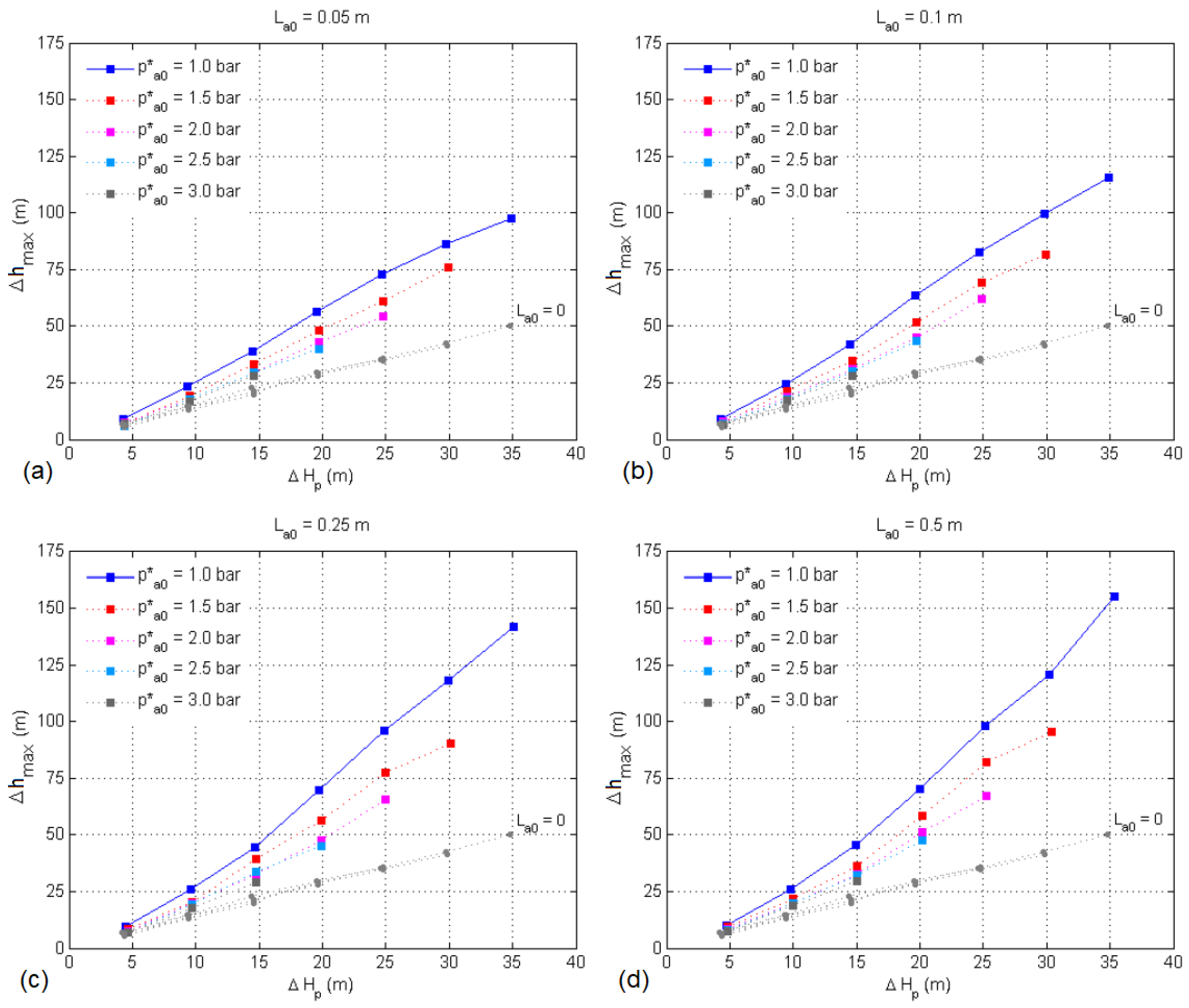
- Pipeline profile—characteristics of high points and inclination of pipes—is highly influential on the proclivity of a system towards air-related issues. It should be emphasized that small elevation differences between upstream and downstream reservoirs result in pressure control issues with a high probability for the occurrence of cavitation during unsteady flow scenarios.
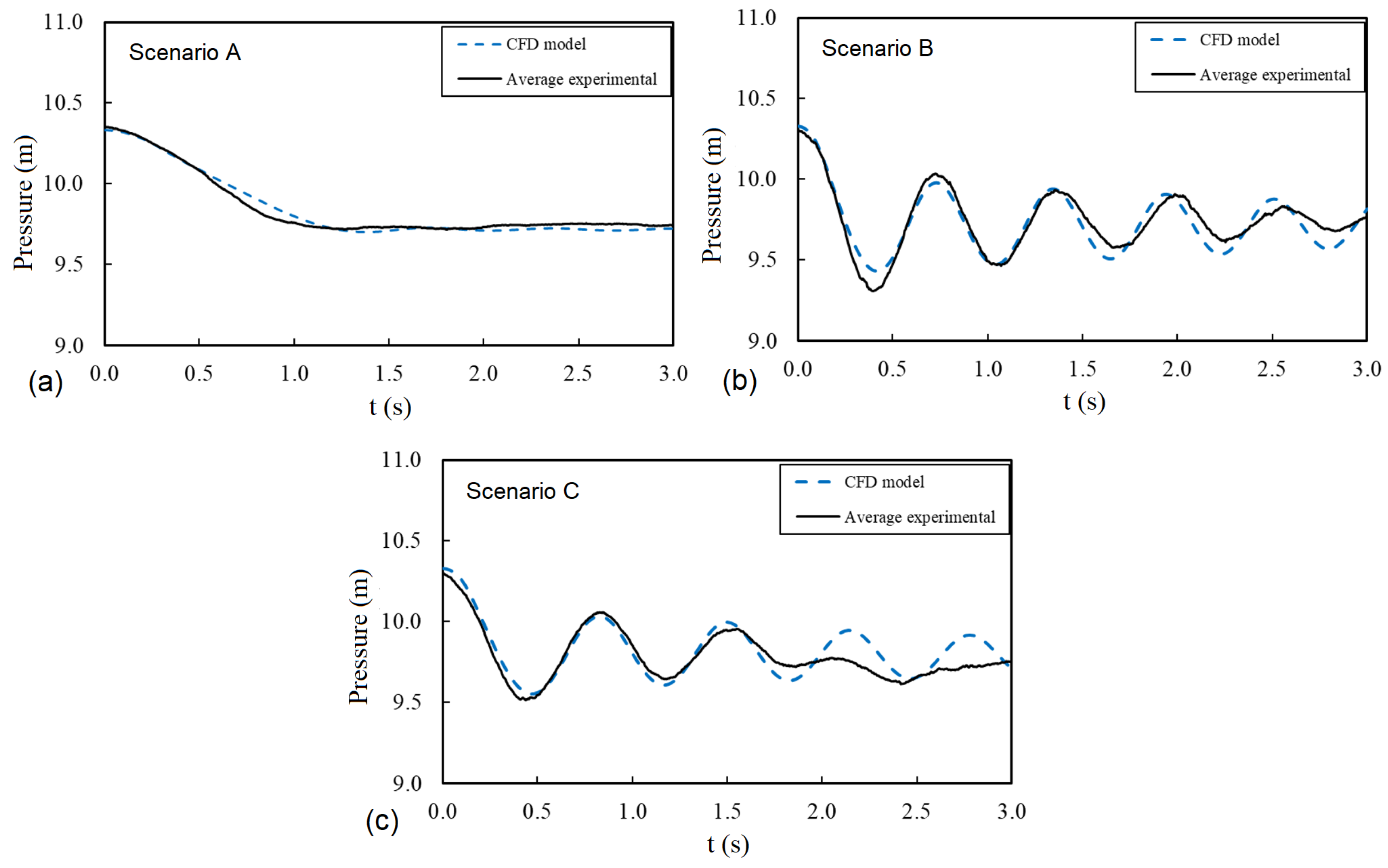
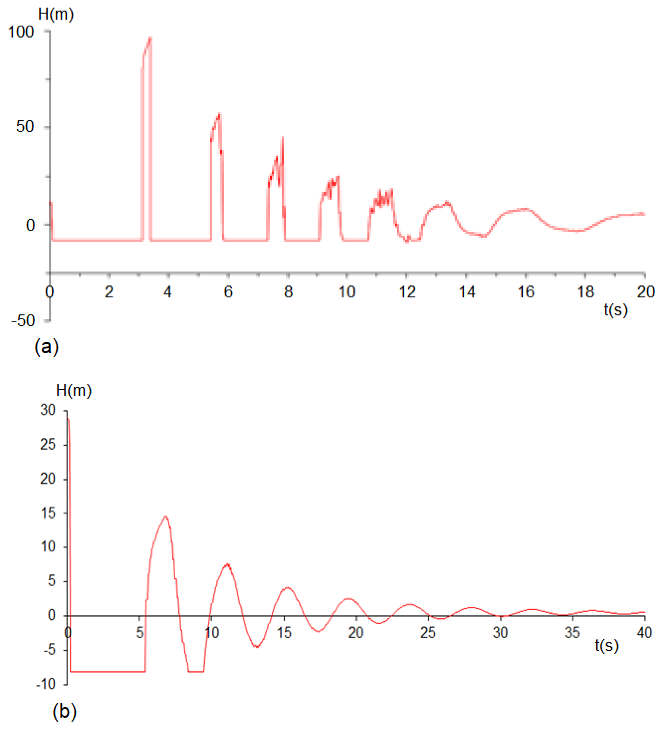
- In the presence of air, the amplitudes of transient pressure oscillations were shown to be consistently higher than those registered with the complete filling of the conduit with water, with a degree of amplification that was found to be a function of the initial conditions of the entrapped air (volume and pressure) and the hydraulic load in the pressurization source.
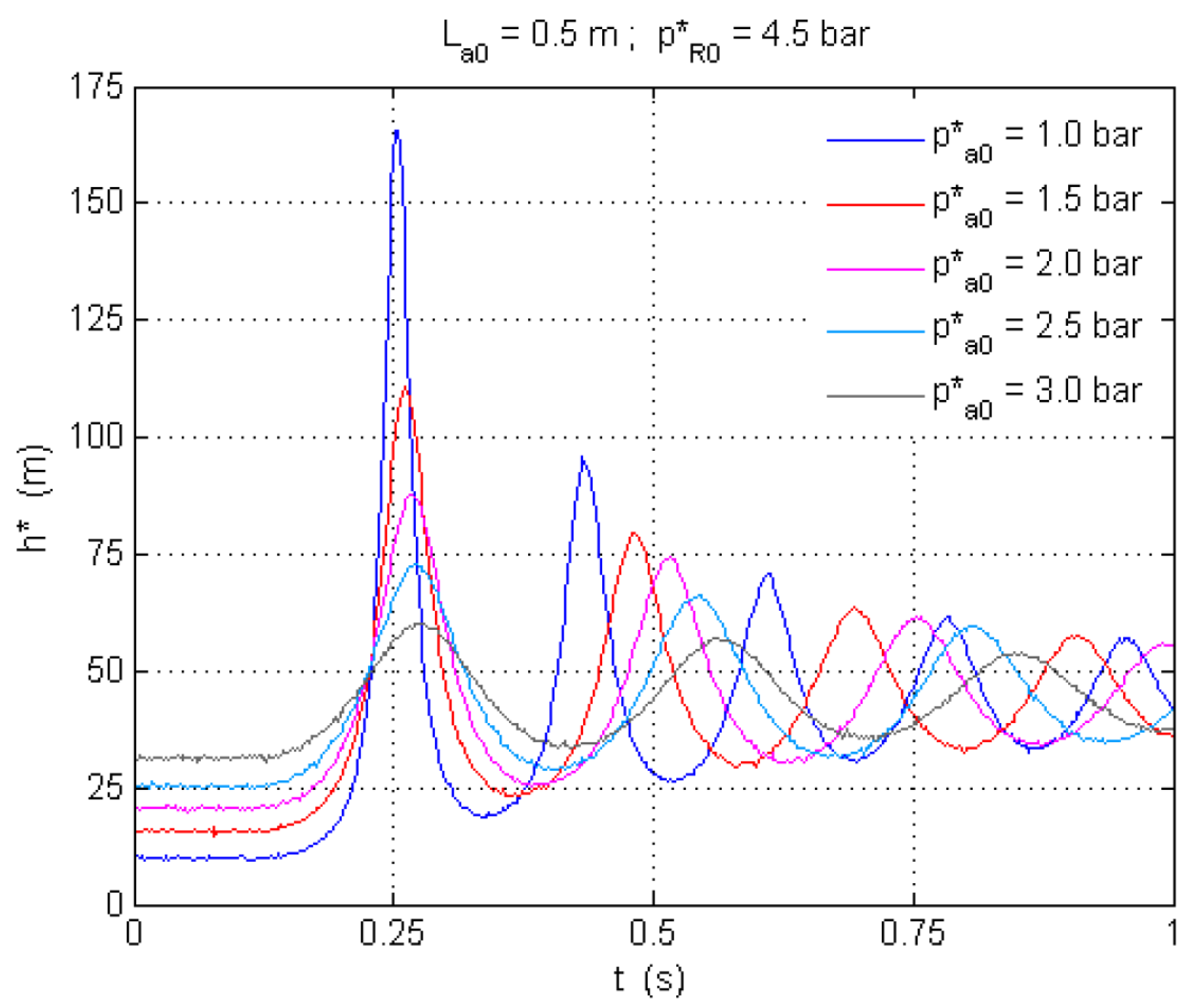
- Higher loads in the pressurization source caused oscillations of greater amplitude and frequency. The initial air pressure also considerably affects the magnitude and frequency of oscillations. As initial air pressure increases, so does the attenuation of transient pressure oscillations.
- The level of amplification, defined in relation to the reference response of the system when only containing water, proved to be greatest under the highest pressurization loads, also being determined by initial air volume and pressure. The amplifications of the tests with trapped air initially at atmospheric pressure varied between about 30% and 200%. Under a higher initial air pressure, the amplification of the pressure fluctuations is considerably reduced.
- The behaviour of the air–water interface is strongly affected by the initial characteristics of the air pocket and also by the initial load differential in the system, presenting a strong disturbance for large initial volumes of trapped air.
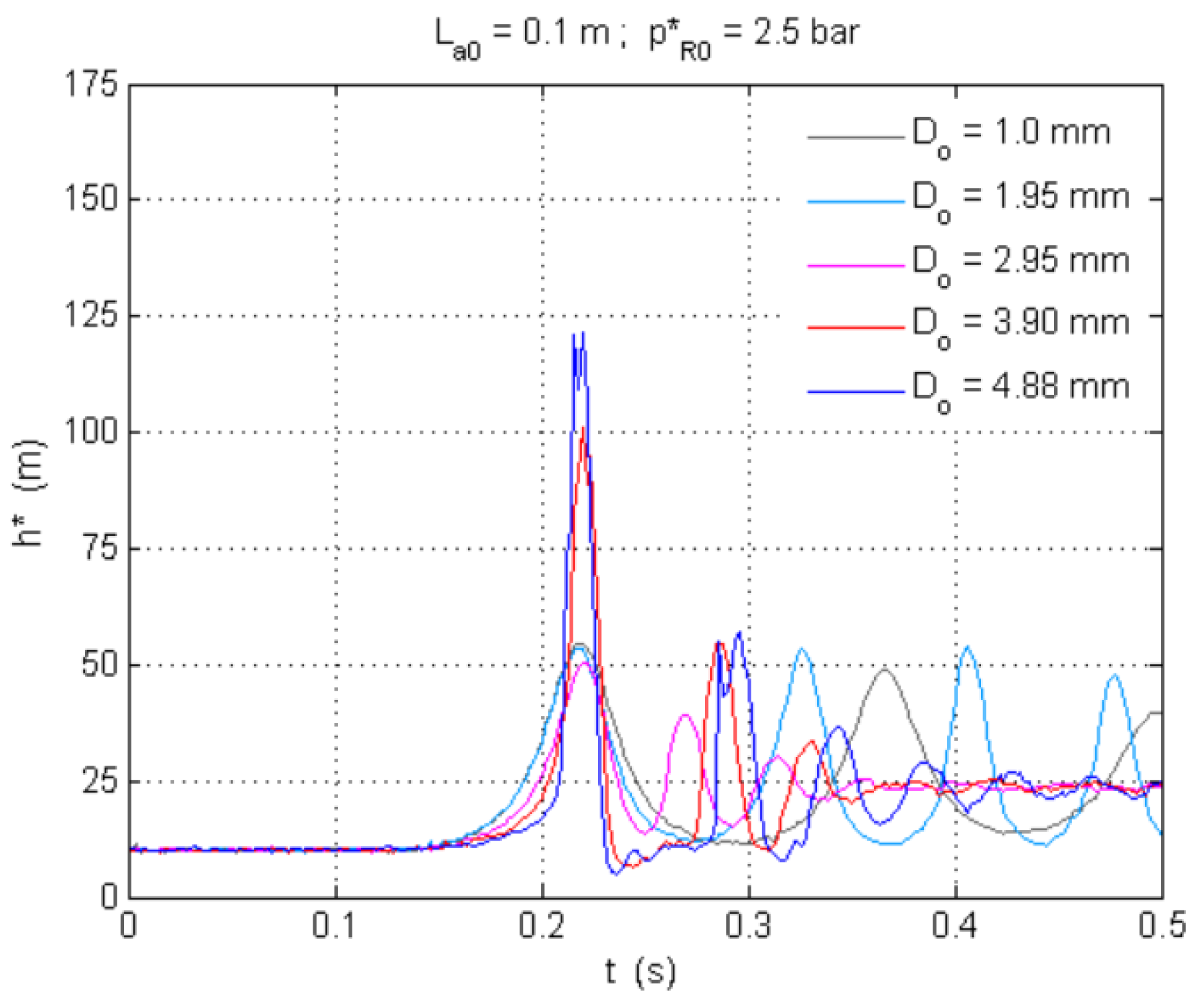
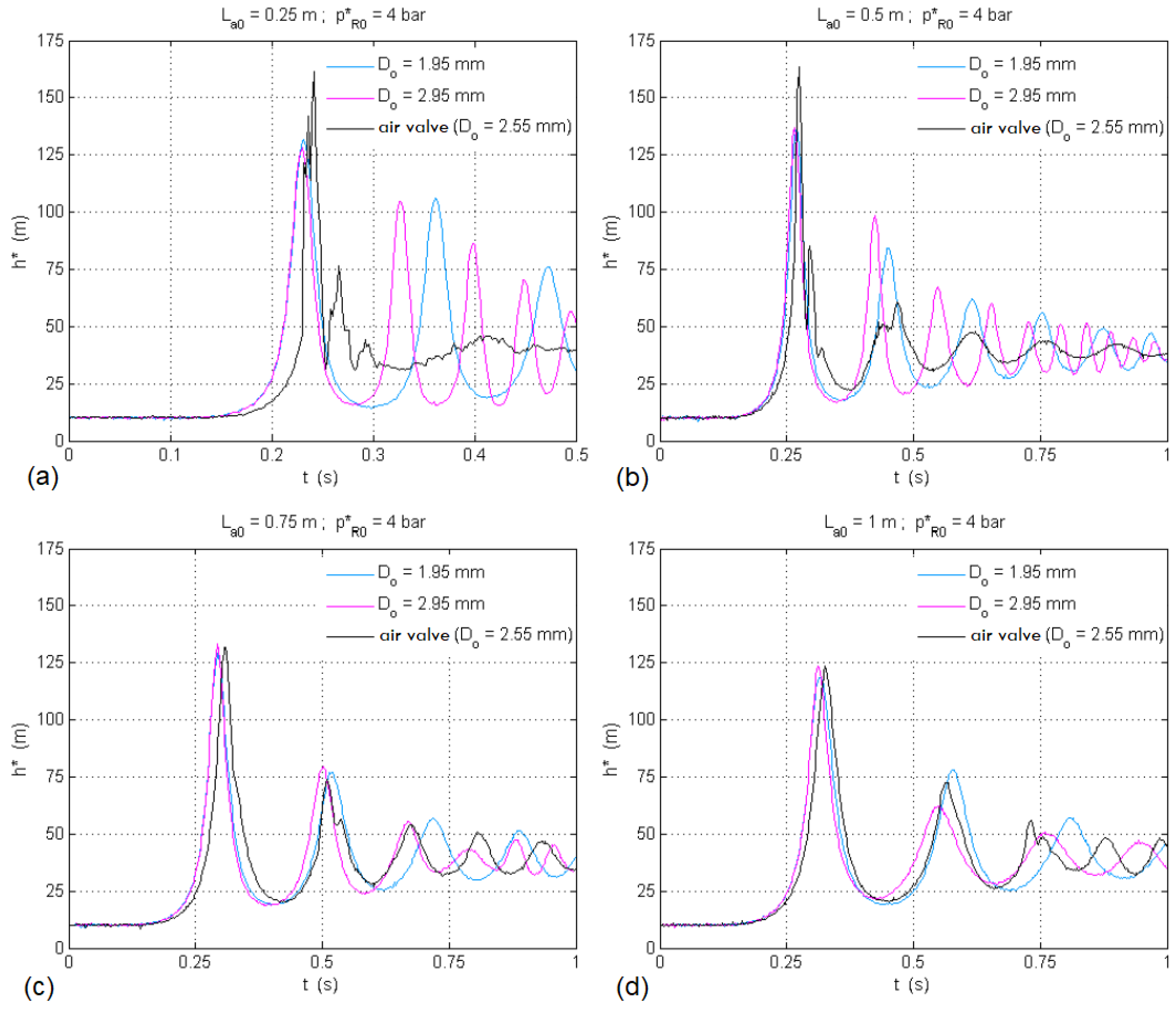
- The presence of any type of orifice in hydraulic systems makes them susceptible to significant transient oscillations, especially in the presence of small volumes of entrapped air and for large orifice dimensions.
- The selection of an air valve orifice for expulsion must consider different sizing aspects. If the air valve is too small, then it is not able to expel the required amount of air, and significant overpressures could be generated. If the air valve has been oversized and is too large, the expelled flow rates are very intense and can generate large overpressures upon air valve closure, even higher than if such a valve was not installed.
- Another important issue in the selection of air valves is the “dynamic closure” that occurs when the float closes prematurely, that is, before the arrival of the water column. When an air valve closes without having completely expelled all the entrapped air, the water column compresses the remaining residual air, producing significant overpressures. Most air/vacuum valves suffer from this issue. However, manufacturers usually do not provide useful information about the dynamic closure of air valves.
- During the emptying process, air valves are selected to protect the installation against possible sub-atmospheric pressures. In this case, the larger the air valve, the greater the intake capacity and the smaller the down-surge produced. However, these same valves will be present for other conditions that might be in conflict with the draining requirements.
Author Contributions
Funding
Acknowledgments
Conflicts of Interest
References
- Lauchlan, C.S.; Escarameia, M.; May, R.W.P.; Burrows, R.; Gahan, C. Air in Pipelines: A Literature Review; HR Wallingford: Oxfordshire, UK, 2005. [Google Scholar]
- Ramezani, L.; Karney, B.; Malekpour, A. The challenge of air valves: A selective critical literature review. J. Water Resour. Plann. Manag. 2015, 141, 04015017. [Google Scholar] [CrossRef]
- Ramezani, L.; Karney, B.; Malekpour, A. Encouraging effective air management in water pipelines: A critical review. J. Water Resour. Plann. Manag. 2016, 142, 04016055. [Google Scholar] [CrossRef] [Green Version]
- Martins, S.C. Dinâmica da Pressurização de Sistemas Hidráulicos Com ar Aprisionado. Ph.D. Thesis, Instituto Superior Técnico, Universidade Técnica de Lisboa, Lisbon, Portugal, 2013. [Google Scholar]
- Tullis, J.P. Hydraulics of Pipelines: Pumps, Valves, Cavitation, Transients; John Wiley & Sons: New York, NY, USA, 1989. [Google Scholar]
- Boulos, P.; Karney, B.; Wood, D.; Lingireddy, S. Hydraulic transient guidelines for protecting water distribution systems. J. Am. Water Work. Assoc. 2005, 97, 111–124. [Google Scholar] [CrossRef]
- Pothof, I.; Karney, B. Guidelines for transient analysis in water transmission and distribution systems. In Water Supply System Analysis–Selected Topics; Ostfeld, A., Ed.; InTech: Rijeka, Croatia, 2012; pp. 1–21. [Google Scholar]
- Zhou, L.; Liu, D.; Karney, B. Investigation of hydraulic transients of two entrapped air pockets in a water pipeline. J. Hydraul. Eng. 2013, 139, 949–959. [Google Scholar] [CrossRef]
- Coronado-Hernández, O.E.; Fuertes-Miquel, V.S.; Besharat, M.; Ramos, H.M. Experimental and numerical analysis of a water emptying pipeline using different air valves. Water 2017, 9, 98. [Google Scholar] [CrossRef]
- Tasca, E.S.A.; Karney, B.; Luvizotto, E., Jr. Performance similarity between different-sized air exchange valves. J. Hydraul. Eng. 2021, 147, 04021036. [Google Scholar] [CrossRef]
- American Water Works Association (AWWA). Manual of Water Supply Practices M51–Air Valves: Air-Release, Air/Vacuum and Combination, 2nd ed.; AWWA: Denver, CO, USA, 2016. [Google Scholar]
- Zhou, L.; Wang, H.; Karney, B.; Liu, D.; Wang, P.; Guo, S. Dynamic behavior of entrapped air pocket in a water filling pipeline. J. Hydraul. Eng. 2018, 144, 04018045. [Google Scholar] [CrossRef]
- Malekpour, A.; Karney, B.; Nault, J. Physical understanding of sudden pressurization of pipe systems with entrapped air: Energy auditing approach. J. Hydraul. Eng. 2016, 142, 04015044. [Google Scholar] [CrossRef] [Green Version]
- Fuertes-Miquel, V.S.; Iglesias-Rey, P.L.; Izquierdo-Sebastián, J.; López-Patiño, G. Algunos problemas generados por ventosas mal seleccionadas a causa de una caracterización hidráulica errónea. In Proceedings of the XXII Congreso Latinoamericano de Hidráulica, Ciudad Guayana, Venezuela, 12–13 October 2006. [Google Scholar]
- Lingireddy, S.; Wood, D.J.; Zloczower, N. Pressure surges in pipeline systems resulting from air releases. J. Am. Water Work. Assoc. 2004, 96, 88–94. [Google Scholar] [CrossRef]
- Tasca, E.S.A.; Dalfré Filho, J.G.; Luvizotto, E., Jr.; Aquino, G.A. The problem of air valves inaccurate air mass flow versus differential pressure curves. In Proceedings of the 1st International WDSA/CCWI Joint Conference, Kingston, ON, Canada, 23–25 July 2018. [Google Scholar]
- Iglesias-Rey, P.L.; Fuertes-Miquel, V.S.; García-Mares, F.J.; Martínez-Solano, J.J. Comparative study of intake and exhaust air flows of different commercial air valves. Procedia Eng. 2014, 89, 1412–1419. [Google Scholar] [CrossRef] [Green Version]
- Fuertes-Miquel, V.S. Hydraulic Transients with Entrapped Air Pockets. Ph.D. Thesis, Department of Hydraulic Engineering, Polytechnic University of Valencia, Valencia, Spain, 2001. [Google Scholar]
- Iglesias-Rey, P.L.; García-Mares, F.J.; Fuertes-Miquel, V.S.; Martínez-Solano, F.J. Air valves characterization using hydrodynamic similarity. In Proceedings of the World Environmental and Water Resources Congress 2017, Sacramento, CA, USA, 21–25 May 2017. [Google Scholar]
- García-Todolí, S.; Iglesias-Rey, P.L.; Mora-Meliá, D.; Martínez-Solano, F.J.; Fuertes-Miquel, V.S. Computational determination of air valves capacity using CFD techniques. Water 2018, 10, 1433. [Google Scholar] [CrossRef] [Green Version]
- Escarameia, M. Investigating hydraulic removal of air from water pipelines. Water Manag. 2007, 160, 25–34. [Google Scholar] [CrossRef]
- Pothof, I.; Clemens, F. Experimental study of air-water flow in downward sloping pipes. Int. J. Multiph. Flow 2011, 37, 278–292. [Google Scholar] [CrossRef]
- Pothof, I.; Clemens, F. On elongated air pockets in downward sloping pipes. J. Hydraul. Res. 2010, 48, 499–503. [Google Scholar] [CrossRef]
- Zheng, G.; Brill, J.P.; Taitel, Y. Slug flow behavior in a hilly terrain pipeline. Int. J. Multiph. Flow 1994, 20, 63–79. [Google Scholar] [CrossRef]
- Edmunds, R.C. Air binding in pipes. J. Am. Water Work. Assoc. 1979, 71, 272–277. [Google Scholar] [CrossRef]
- Pozos, O.; Gonzalez, C.A.; Giesecke, J.; Marx, W.; Rodal, E.A. Air entrapped in gravity pipeline systems. J. Hydraul. Res. 2010, 48, 338–347. [Google Scholar] [CrossRef]
- Besharat, M.; Coronado-Hernández, O.E.; Fuertes-Miquel, V.S.; Viseu, M.T.; Ramos, H.M. Computational fluid dynamics for sub-atmospheric pressure analysis in pipe drainage. J. Hydraul. Res. 2020, 58, 553–565. [Google Scholar] [CrossRef]
- Zhou, L.; Liu, D.; Karney, B.; Zhang, Q. Influence of entrapped air pockets on hydraulic transients in water pipelines. J. Hydraul. Eng. 2011, 137, 1686–1692. [Google Scholar] [CrossRef] [Green Version]
- Zhou, L.; Liu, D.; Karney, B.; Wang, P. Phenomenon of white mist in pipelines rapidly filling with water with entrapped air pockets. J. Hydraul. Eng. 2013, 139, 1041–1051. [Google Scholar] [CrossRef]
- Martin, C.S.; Lee, N.H. Rapid expulsion of entrapped air through an orifice. In Proceedings of the 8th International Conference on Pressure Surges, The Hague, Netherlands, 12–14 April 2000. [Google Scholar]
- Zhou, F.; Hicks, F.E.; Steffler, P.M. Transient flow in a rapidly filling horizontal pipe containing trapped air. J. Hydraul. Eng. 2002, 128, 625–634. [Google Scholar] [CrossRef]
- Zhou, F.; Hicks, F.E.; Steffler, P.M. Observations of air-water interaction in a rapidly filling horizontal pipe. J. Hydraul. Eng. 2002, 128, 635–639. [Google Scholar] [CrossRef]
- Zhou, F.; Hicks, F.E.; Steffler, P.M. Analysis of effects of air pocket on hydraulic failure of urban drainage infrastructure. Can. J. Civ. Eng. 2004, 31, 86–94. [Google Scholar] [CrossRef]
- De Martino, G.; Fontana, N.; Giugni, M. Transient flow caused by air expulsion through an orifice. J. Hydraul. Eng. 2008, 134, 1395–1399. [Google Scholar] [CrossRef] [Green Version]
- Zhou, L.; Pan, T.; Wang, H.; Liu, D.; Wang, P. Rapid air expulsion through an orifice in a vertical water pipe. J. Hydraul. Res. 2019, 57, 307–317. [Google Scholar] [CrossRef]
- Zhou, L.; Cao, Y.; Karney, B.; Bergant, A.; Tijsseling, A.; Liu, D.; Wang, P. Expulsion of entrapped air in a rapidly filling horizontal pipe. J. Hydraul. Eng. 2020, 146, 04020047. [Google Scholar] [CrossRef]
- Coronado-Hernández, O.E.; Fuertes-Miquel, V.S.; Angulo-Hernández, F.N. Emptying operation of water supply networks. Water 2018, 10, 22. [Google Scholar] [CrossRef] [Green Version]
- Besharat, M.; Coronado-Hernández, O.E.; Fuertes-Miquel, V.S.; Viseu, M.T.; Ramos, H.M. Backflow air and pressure analysis in emptying a pipeline containing an entrapped air pocket. Urban Water J. 2018, 15, 769–779. [Google Scholar] [CrossRef]
- Fuertes-Miquel, V.S.; López-Jiménez, P.A.; Martínez-Solano, F.J.; López-Patiño, G. Numerical modelling of pipeline with air pockets and air valves. Can. J. Civ. Eng. 2016, 43, 1052–1061. [Google Scholar] [CrossRef] [Green Version]
- Wylie, E.B.; Streeter, V.L. Fluid Transients; FEB Press: Ann Arbor, MI, USA, 1983. [Google Scholar]
- White, F.M. Fluid Mechanics; McGraw-Hill: New York, NY, USA, 2011. [Google Scholar]
- American Water Works Association (AWWA). Manual of Water Supply Practices M51–Air-Release, Air/Vacuum, and Combination Air Valves, 1st ed.; AWWA: Denver, CO, USA, 2001. [Google Scholar]
- Tasca, E.S.A.; Karney, B.; Besharat, M.; Ramos, H.M.; Zhou, L. Insights and challenges associated with air in pressurized water conveyance systems. In Proceedings of the World Environmental and Water Resources Congress 2022, Atlanta, GA, USA, 5–8 June 2022. [Google Scholar]
- ANSI/AWWA. C512-92–Air-Release, Air/Vacuum, and Combination Air Valves for Waterworks Service; AWWA: Denver, CO, USA, 1992. [Google Scholar]
- ANSI/AWWA. C512-99–Air-Release, Air/Vacuum, and Combination Air Valves for Waterworks Service; AWWA: Denver, CO, USA, 1999. [Google Scholar]
- ANSI/AWWA. C512-04–Air-Release, Air/Vacuum, and Combination Air Valves for Waterworks Service; AWWA: Denver, CO, USA, 2004. [Google Scholar]
- ANSI/AWWA. C512-07–Air-Release, Air/Vacuum, and Combination Air Valves for Waterworks Service; AWWA: Denver, CO, USA, 2008. [Google Scholar]
- ANSI/AWWA. C512-15–Air-Release, Air/Vacuum, and Combination Air Valves for Water and Wastewater Service; AWWA: Denver, CO, USA, 2015. [Google Scholar]
- McPherson, D.L. Air valve sizing and location: A prospective. In Proceedings of the Pipelines 2009: Infrastructure’s hidden assets, San Diego, CA, USA, 15–19 August 2009. [Google Scholar]
- Besner, M.C.; Ebacher, G.; Jung, B.S.; Karney, B.; Lavoie, J.; Payment, P.; Prévost, M. Negative pressures in full-scale distribution system: Field investigation, modelling, estimation of intrusion volumes and risk for public health. Drink. Water Eng. Sci. 2010, 3, 101–106. [Google Scholar] [CrossRef] [Green Version]
- McPherson, D.L.; Haeckler, C. Untangling the mysteries of air valves. In Proceedings of the Pipelines 2012: Innovations in Design, Constructing, Operations, and Maintenance, Doing More with Less, Miami Beach, FL, USA, 19–22 August 2012. [Google Scholar]
- Beieler, R. What every conveyance designer should know about air valves and air valve assemblies. In Proceedings of the Pipelines 2016: Out of Sight, Out of Mind, Not Out of Risk, Kansas City, MO, USA, 17–20 July 2016. [Google Scholar]
- Ramezani, L.; Daviau, J. The challenge of air valve selection in pumping systems. In Proceedings of the Pipelines 2021, Online, 3–6 August 2021. [Google Scholar]
- Ramezani, L.; Karney, B. Water column separation and cavity collapse for pipelines protected with air vacuum valves: Understanding the essential wave processes. J. Hydraul. Eng. 2017, 143, 04016083. [Google Scholar] [CrossRef] [Green Version]
- Coronado-Hernández, O.E.; Fuertes-Miquel, V.S.; Besharat, M.; Ramos, H.M. A parametric sensitivity analysis of numerically modelled piston-type filling and emptying of an inclined pipeline with an air valve. In Proceedings of the 13th International Conference on Pressure Surges, Bordeaux, France, 14–16 November 2018. [Google Scholar]
- Fuertes-Miquel, V.S.; Coronado-Hernández, O.E.; Mora-Meliá, D.; Iglesias-Rey, P.L. Hydraulic modeling during filling and emptying processes in pressurized pipelines: A literature review. Urban Water J. 2019, 16, 299–311. [Google Scholar] [CrossRef]
- Aguirre-Mendoza, A.M.; Paternina-Verona, D.A.; Oyuela, S.; Coronado-Hernández, O.E.; Besharat, M.; Fuertes-Miquel, V.S.; Iglesias-Rey, P.L.; Ramos, H.M. Effects of orifice sizes for uncontrolled filling processes in water pipelines. Water 2022, 14, 888. [Google Scholar] [CrossRef]
- Ramezani, L. An Exploration of Transient Protection of Pressurized Pipelines Using Air Valves. Ph.D. Thesis, University of Toronto, Toronto, ON, Canada, 2015. [Google Scholar]
- Borga, A.; Ramos, H.M.; Covas, D.; Dudlik, A.; Neuhaus, T. Dynamic effects of transient flows with cavitation in pipe systems. In Proceedings of the 9th International Conference on Pressure Surges, Chester, UK, 24–26 March 2004. [Google Scholar]
- Ramos, H.M.; Borga, A.; Bergant, A.; Covas, D.; Almeida, A.B. Analysis of surge effects in pipe systems by air release/venting. Port. J. Water Resour. 2005, 26, 45–55. [Google Scholar]
- Ramos, H.M.; Covas, D.; Borga, A.; Loureiro, D. Surge damping analysis in pipe systems: Modelling and experiments. J. Hydraul. Res. 2004, 42, 413–425. [Google Scholar] [CrossRef]
- Ramos, H.M.; Borga, A. Surge effects in pressure systems for different pipe materials. In Advances in Water Resources and Hydraulic Engineering; Springer: Berlin/Heidelberg, Germany, 2009; pp. 2152–2156. [Google Scholar]


Publisher’s Note: MDPI stays neutral with regard to jurisdictional claims in published maps and institutional affiliations. |
© 2022 by the authors. Licensee MDPI, Basel, Switzerland. This article is an open access article distributed under the terms and conditions of the Creative Commons Attribution (CC BY) license (https://creativecommons.org/licenses/by/4.0/).
Share and Cite
Ramos, H.M.; Fuertes-Miquel, V.S.; Tasca, E.; Coronado-Hernández, O.E.; Besharat, M.; Zhou, L.; Karney, B. Concerning Dynamic Effects in Pipe Systems with Two-Phase Flows: Pressure Surges, Cavitation, and Ventilation. Water 2022, 14, 2376. https://doi.org/10.3390/w14152376
Ramos HM, Fuertes-Miquel VS, Tasca E, Coronado-Hernández OE, Besharat M, Zhou L, Karney B. Concerning Dynamic Effects in Pipe Systems with Two-Phase Flows: Pressure Surges, Cavitation, and Ventilation. Water. 2022; 14(15):2376. https://doi.org/10.3390/w14152376
Chicago/Turabian StyleRamos, Helena M., Vicente S. Fuertes-Miquel, Elias Tasca, Oscar E. Coronado-Hernández, Mohsen Besharat, Ling Zhou, and Bryan Karney. 2022. "Concerning Dynamic Effects in Pipe Systems with Two-Phase Flows: Pressure Surges, Cavitation, and Ventilation" Water 14, no. 15: 2376. https://doi.org/10.3390/w14152376