Communication

Performance of Newly Developed Intermittent Aerator for Flat-Sheet Ceramic Membrane in Industrial MBR System

1
Meiden Singapore Pte Ltd., Singapore 619363, Singapore
2
Public Utilities Board, Singapore’s National Water Agency, Singapore 228231, Singapore
3
Separation Technologies Applied Research and Translation (START) Centre, Nanyang Technological University—NTUitive Pte Ltd., Singapore 639798, Singapore
*
Authors to whom correspondence should be addressed.
Water 2022, 14(15), 2286; https://doi.org/10.3390/w14152286
Submission received: 19 May 2022 / Revised: 12 July 2022 / Accepted: 20 July 2022 / Published: 22 July 2022

Abstract

:
An intermittent aerator was newly developed to reduce energy costs in a flat-sheet ceramic membrane bioreactor (MBR) for industrial wastewater treatment. Large air bubbles were supplied over a short time interval by the improved aerator technology at the bottom of the flat-sheet membrane. Performance tests for the intermittent aerator were carried out in a pilot system with two cassettes immersed in a membrane tank of the 1-MGD demonstration plant at Jurong Water Reclamation Plant (JWRP) in Singapore. Stable operation was achieved at an average flow of 19–22 LMH with every-2-days MC and peak flow of 27 to 33 LMH with daily MC with reduced air flow for membrane aeration. This indicates that energy costs for membrane aeration can be reduced by using the intermittent aerator. Stable MBR operation with a projected 43% reduction in the overall operating costs could be achieved with an improved aerator together with improved MC regime and membrane cassette.

1. Introduction

The membrane bioreactor (MBR) has been widely used for treatment of domestic sewage and industrial wastewater [1,2]. The MBR system has the advantages of smaller footprint, higher quality of product water, stability of bioprocess and shorter retention times compared to conventionally activated sludge processes [3,4,5]. Membrane aeration is a key operational parameter and has a significant impact on the energy costs of the MBR system [6,7,8]. Membrane aeration is applied to prevent fouling on the surface of the membrane, and not only provides oxygen to the biomass in the membrane tank, but also scours the membrane surface and maintains solids in suspension to control the fouling layer on the membrane surface. Many researchers have carried out trials to reduce energy for membrane aeration through novel methods such as controlling aeration for bioprocess [5,9,10,11,12,13] and reducing membrane scouring air [14,15,16,17]. On–off control of scouring air has been developed to reduce scouring air [14,15] while pulsed air for membrane scouring has been utilized to reduce the required amount of air [16,17]. An intermittent aerator has been developed by MEIDEN and Separation Technologies Applied Research and Translation (START) Centre to reduce the required air amount for membrane scouring, which results in a reduction of energy consumption in the membrane filtration system. PUB, Singapore’s National Water Agency, has developed a one million gallons per day (1 MGD) demonstration plant (DEMO) at Jurong Water Reclamation Plant (JWRP), Singapore, to treat high-strength industrial wastewater from an industrial estate. MEIDEN’s Ceramic Membrane Bioreactor (CMBR) process has been installed and operational at the plant since 2014 [14]. It has been demonstrated and reported widely in the literature that the CMBR system can produce high-quality water for reuse application [6,7,9,15,16,17,18]. A new intermittent aerator with pulsated, lower air flow was developed by MEIDEN and START Centre, for energy reduction in the CMBR system. The performance evaluation of the intermittent aerator was carried out in the DEMO plant at JWRP to assess the feasibility and extent of energy reduction for the CMBR system. The stability of membrane filtration was investigated with the intermittent aerator at reduced air flow compared with that for the conventional continuous aerator.

2. Materials and Methods

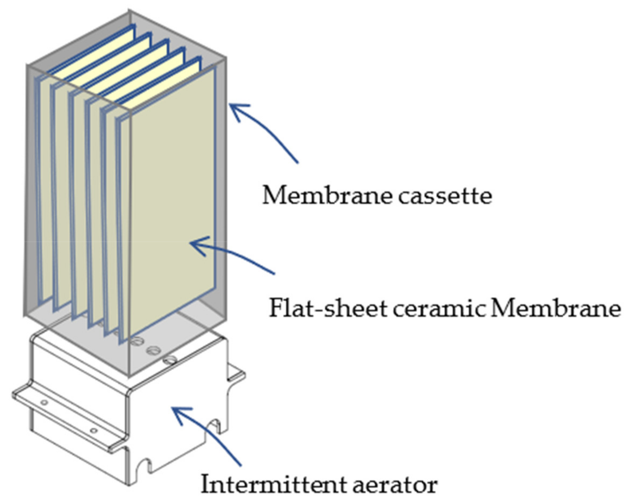
2.1. Intermittent Aerator Tank Operation Principles

An intermittent aerator was developed to release large air bubbles at the bottom of the flat-sheet ceramic membrane with a width of 250 mm (Figure 1). The intermittent aerator can release larger bubbles from ϕ24 mm air release holes as compared to the ϕ6 mm air release holes from a conventional continuous aerator. Air is continuously supplied from air pipes at the bottom of the intermittent aerator; it is accumulated in the air chamber of the aerator and is released in 0.75 sec with 3.5 sec of air release interval to produce large air bubbles. Air bubbles from the ϕ24 mm air release holes were split into the gaps of 10 mm to produce mixed air and water flow in the gaps as is shown in Figure 2.
Multiphase CFD simulations were performed by the Eulerian model in Ansys® Fluent, Release 19.2 (Ansys, Canonsburg, PA, USA) with water as the primary phase and air as the secondary phase. The boundary conditions assumed for the modelling include: (a) symmetry on the size of the membrane cassette, and (b) air entrainment from bottom to top. The material properties used in the simulation are defined in Table 1 below. The air mass flow rate was converted accordingly to correspond with the air flowrate of 2.2 m3/min and the number of holes that exist throughout the air-scouring pipes. To improve the convergence behavior, an initial solution was computed before solving the complete Eulerian multiphase model. In this work, a mass-flow inlet boundary condition was utilized to initialize the flow conditions. It is also more recommended to set the value of the volume fraction close to the value of the volume fraction at the inlet. At the beginning of the solution, a lower time step i.e., 0.001 s was used and recommended in order to reach convergence. In addition, a sufficient number of iterations (i.e., 30) are required to maintain the convergence level at each time step. The simulation was executed until the end time of 9 s to ensure that there has been a flow stability reaching the top part of the two-level stack membrane unit that would be fully submerged inside water.

2.2. Test Systems

Performance tests of the new aeration system were carried out at the 1-MGD DEMO MBR plant at JWRP. The DEMO plant consisted of an Up-flow Anaerobic Sludge Blanket (UASB) reactor, aeration and membrane separation tanks. Wastewater from the industrial estate was treated in a UASB reactor followed by an MBR system using flat-sheet ceramic membrane [6]. Two commercial membrane cassettes with flat-sheet ceramic membranes manufactured by MEIDENSHA Corporation were used for the performance tests. Each cassette had 400 membrane sheets with an effective area of 200 m2. One membrane cassette (Train 1) was equipped with the newly developed intermittent aerator while the other cassette (Train 2) was installed with a conventional continuous aerator, in which air was supplied from 6-mm air release holes on the PVC pipes. The two cassettes were immersed in a membrane tank of the 1-MGD DEMO plant, and they were independently operated by using a control panel. ON–OFF control air supply for the continuous aerator was also carried out in Train 2, for comparison.

2.3. Operating Conditions

Membrane filtration was carried out under similar conditions for Train 1 and Train 2, except for the membrane aeration condition. The filtration/backwash cycle was fixed at 10 min; backwash duration was 30 s with a flow rate of 1.5 Q (Q = filtration flow). Different flux conditions were set to check membrane stability at average and peak flow conditions (Table 2).
Maintenance cleaning (MC) was carried out with 250 mg/L sodium hypochlorite (NaClO) every two days for the average flow and daily for the peak flow (Table 2). Average flow setting assumed normal operating conditions with full operation of membrane filtration tanks in the membrane systems. Peak flow setting was for higher flux condition when one or two membrane tanks were out of service during maintenance or recovery cleaning. Long-term operation was carried out with average and continuous flux settings to observe filtration stability and impact of peak flow between average flow operation.
Air flow for the intermittent aerator (Train 1) and the continuous aerator (Train 2) was set to 35 m3/h/train and that for the continuous aerator (Train 2) was set to 66 m3/h/train, which corresponded to 5.3 m3-air/m3-permeate and 10 m3-air/m3-permeate as specific air demand per permeate (SADp) at 33 L/m2/h (LMH). Air flow setting for the intermittent aerator was 53% of that for conventional continuous aerator.

3. Results and Discussion

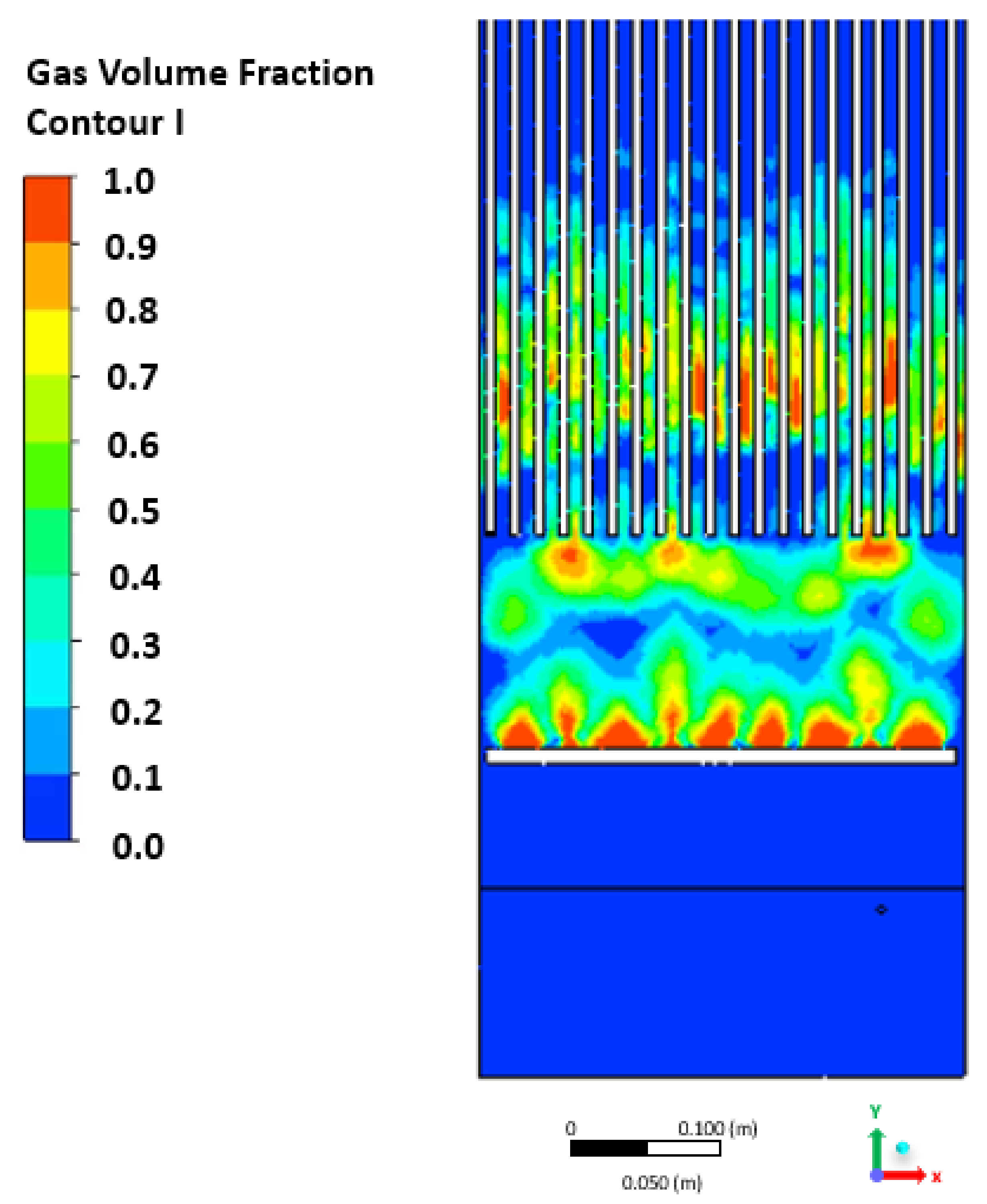
3.1. CFD Analysis for the Intermittent Aerator

Figure 2 shows CFD analysis results of air flow by the intermittent aerator. The large air bubbles released from the bottom of the membrane cassette were evenly distributed in between the gaps of 10 mm for the membrane sheets. Multiphase CFD simulations were performed with the Eulerian model in Ansys® Fluent, Release 19.2. As an unstructured solver, Ansys® Fluent used internal data structures to assign an order to the cells, faces, and grid points in a mesh and to maintain contact between adjacent cells. Upon generating the grids, the minimum orthogonal quality of the whole CFD model was up to 0.067 which shows a high quality of the mesh, and that quality plays a significant role in the accuracy and stability of the numerical computation. Ansys Fluent allows the user to evaluate the mesh quality through a quantity called orthogonality. Orthogonal quality was computed for cells using cell skewness and the vector from the cell centroid to each of its faces, the corresponding face area vector, and the vector from the cell centroid to the centroids of each of the adjacent cells. If the orthogonality exceeds the limits the numerical error will be higher, which will lead to solution convergence issues. The minimum orthogonal quality for all types of cells should be more than 0.01, with an average value that is significantly higher.

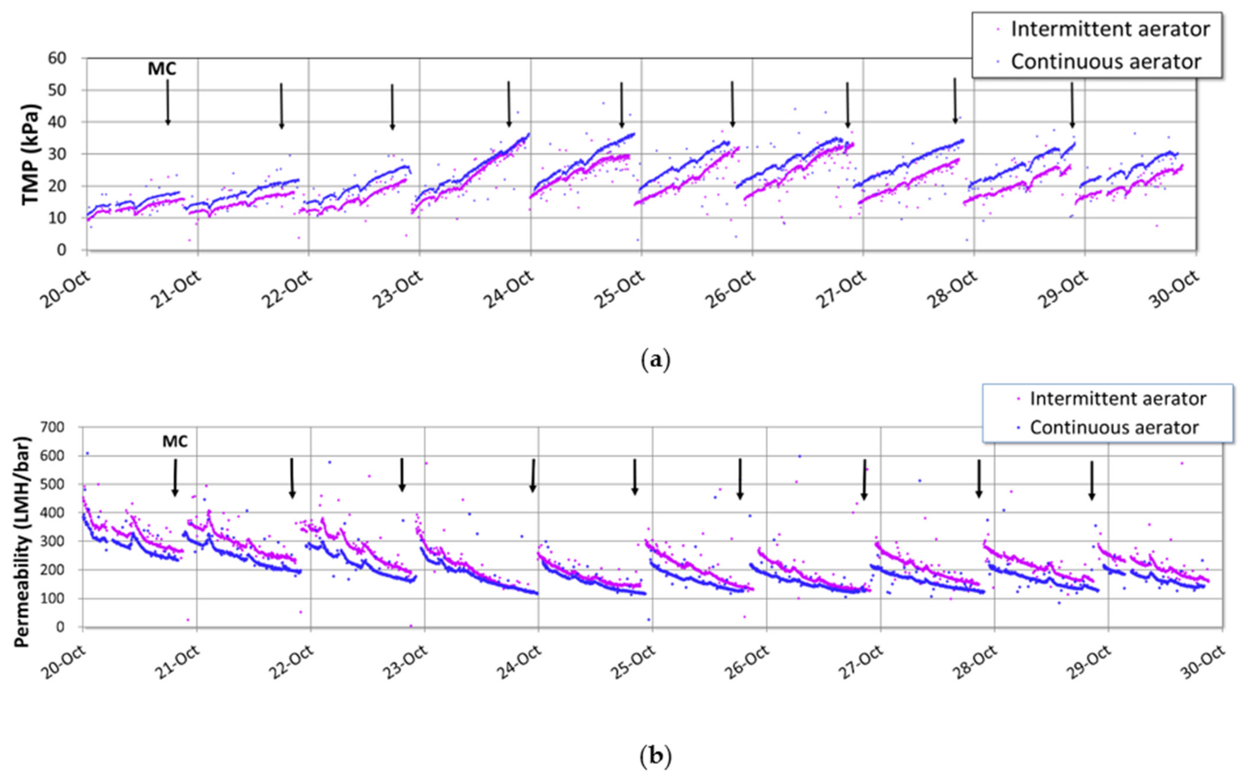
3.2. Performance with Intermittent Aerator

The trans-membrane pressure (TMP) and the permeate flux data were obtained and collated for five months of continuous operation, to determine the long-term efficiency of the intermittent aerator. Figure 3 and Figure 4 show the profiles of comparison (1) TMP and (2) permeability between the two aerators with permeate flux settings at 22 LMH and 33 LMH, respectively. From Figure 3, base TMP after each MC for the intermittent aerator was lower than a conventional continuous aerator. However, TMP trends became similar for intermittent and continuous aerators after plant shut down on 15th August. Aeration for bioprocess was stopped during the shut down period, which might have caused lower COD or BOD removal in the activated sludge system; this could be attributed to potential membrane fouling when the organics became more dominant after the plant shut down and the reducing impact of the larger bubbles from the intermittent aerator on membrane surface resulted in a similar TMP increase for intermittent and continuous aerators.
Figure 4 shows TMP and permeability for the intermittent and continuous aeration methods at flux of 33 LMH. TMP increases between MC for the intermittent aerator, ranging from 5 to 23 kPa. This was much higher than that at 22 LMH which has the TMP ranged from 2 to 5 kPa for the intermittent aerator. Both base TMP and TMP after MC have become stable at around 15 to 17 kPa after 24th October, which indicates that stable operation was achieved with the intermittent aerator at 33 LMH.
From Figure 4, it is shown that the performance of TMP and permeability of the intermittent aeration method surpassed the conventional continuous aeration method at a higher flux of 33 LMH. This can be observed from Figure 4a where TMP increase between MC for the intermittent aeration was lower than the conventional continuous aeration method. The Figure 4b also shows a higher consistency in permeability data using the intermittent aeration method than that of the conventional continuous aeration method.
Membrane fouling occurs on the surface of the membrane by formation of a cake layer and inside of the pores by the accumulation of foulants. As membrane air can remove foulants on the surface of the membrane and foulants inside of the membrane pores can be removed by backwashing and chemical cleaning during MC. As air flow on the surface of the membrane mitigates the cake layer formation [18], the difference in increase in TMP between MC for the intermittent and continuous aerator might be attributed to the difference in formation of cake layer on the surface. Shear force was obtained from the CFD analysis. Average shear force in a membrane cassette for the intermittent aerator was 11.22 µST, while that for the continuous aerator was 6.97 µST. Higher shear force resulting from larger air bubbles from the intermittent aerator can strongly reduce foulants on the surface compared with the continuous aerator. This might result in a lower increase in TMP between MC for the intermittent aerator. Reduced formation of cake layer during filtration can affect the efficiency of backwashing, which might result in lower base TMP for the intermittent aerator. Cake layer formation might become faster at higher flux setting of 33 LMH. This might result in more significant suppression of TMP increase with intermittent aerator than the flux condition of 22 LMH.

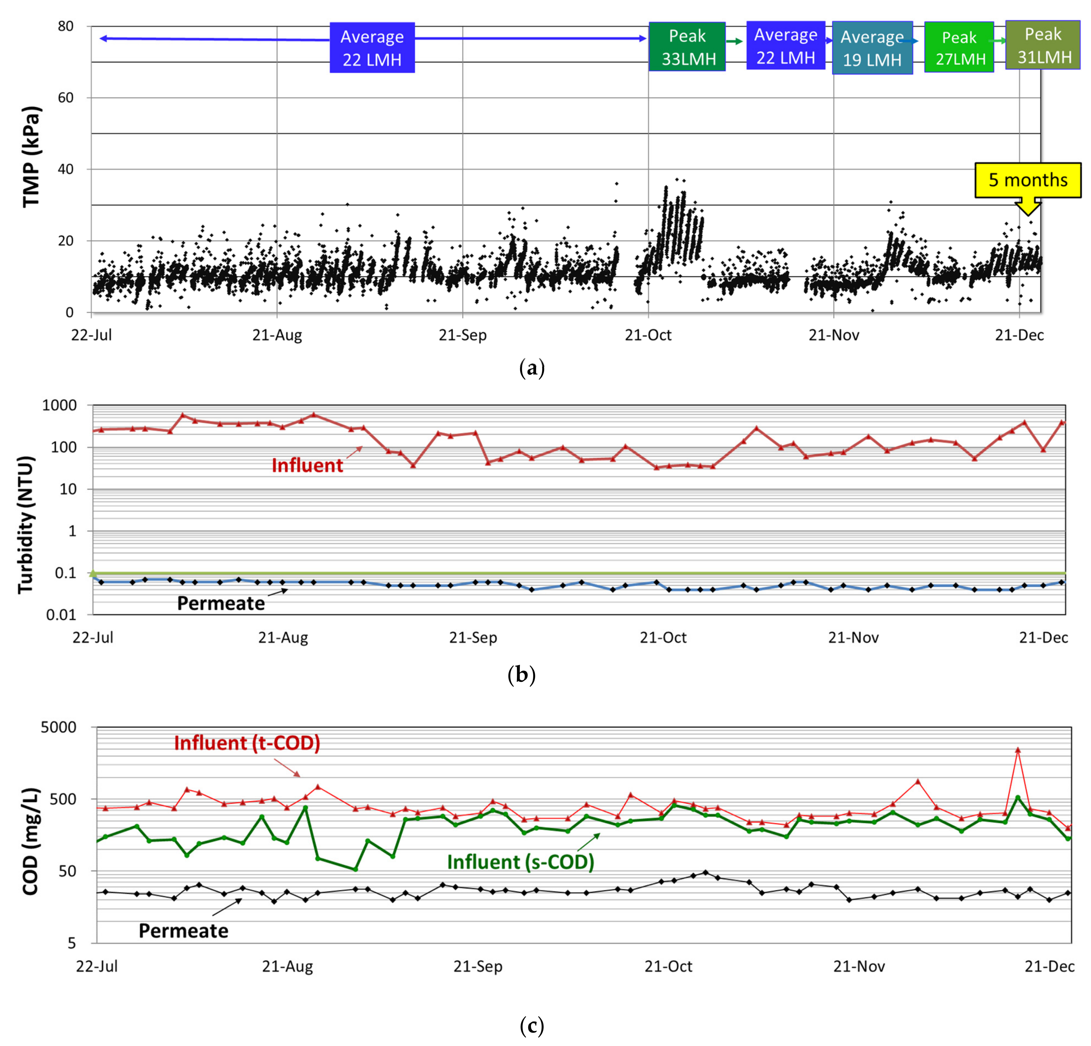
3.3. Long-Term Operation

Figure 5a presents the TMP trend graph of the intermittent aerator operation with various flux settings over a period of five months without recovery cleaning (RC). The results indicate that stable operation can be achieved with the intermittent aerator to reduce air consumption while achieving sustainable flux.
SADp was reduced to 5.3 m3-air/m3-permeate by using the newly developed intermittent aerator, and longer-term stability was shown in the large-scale MBR plant in JWRP. SADp in full-scale plant ranges from 10 to 50 m3-air/m3-permeate [19]. Some researchers reported achievements of lower SADp ranging from 6 to 9 m3-air/m3-permeate with polymeric hollow fiber membrane in lab or pilot scale tests for MBR systems [7,10]. Reduction of SADp to 5.3 m3-air/m3-permeate for the flat-sheet membrane system was similar to the range achieved for the hollow fiber membrane system, suggesting that similar energy for membrane scouring for the flat-sheet ceramic membranes can be almost the same level as that for hollow fiber polymeric membrane. Achievement of lower SADp at 5.3 m3-air/m3-permeate is a significant development for MBR systems, especially for flat-sheet membranes whose footprint is larger than those for hollow fiber membranes. Flat-sheet ceramic membrane can withstand higher shear force by larger air bubbles, which enables lower SADp in MBR system.
Turbidity is an indicator of performance in water and wastewater applications. Thus, it is monitored regularly to ensure treatment systems are operating effectively. Figure 5b shows that the turbidity of the MBR permeate remained constant at ≤0.1 NTU throughout the testing period, regardless of the wide variations in turbidity for raw wastewater that ranged between 30 NTU and 600 NTU. As shown in Figure 5c, due to the industrial nature of influent, the COD of feed water to the MBR fluctuated with values ranging between 150 and 2500 mg/L. Despite the variable characteristics of the influent, the MBR was able to consistently produce a permeate with COD ≤ 50 mg/L. The results showed the robustness of the aerobic biological process. The consistent permeate quality also indicated stable operation of the ceramic membrane system.

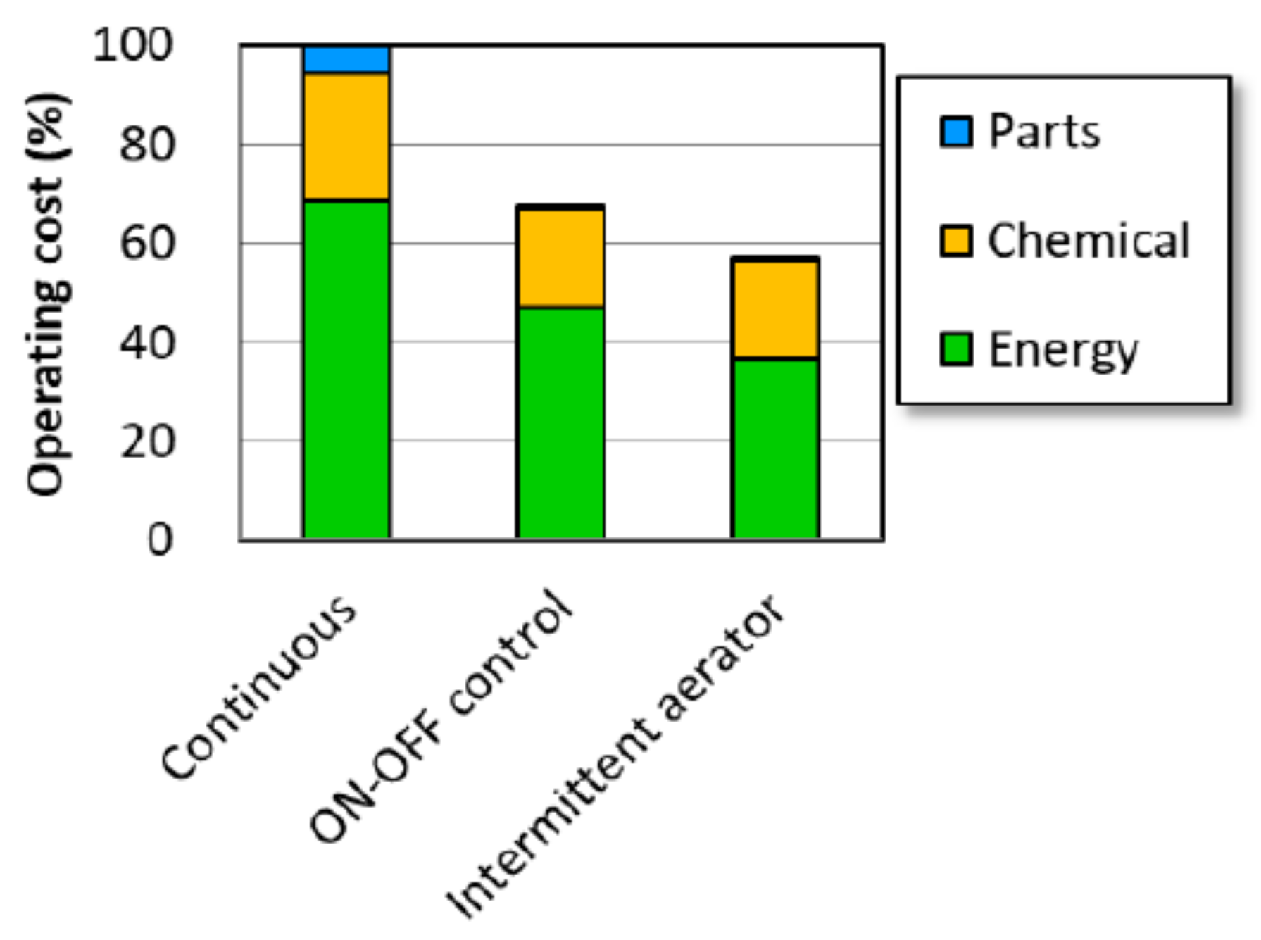
3.4. Analysis of Operating Costs

Analysis of operation costs was carried out to show the impact of the improved membrane aeration method, and cost analysis was done for large scale MBR with a capacity of 20 MGD as a case study. Energy costs were estimated for the intermittent aerator and compared with the conventional continuous aerator and ON–OFF control of the continuous aerator. The 7 min-ON and 3 min-OFF conditions were used for the analysis of ON–OFF control. Chemical costs included MC with NaClO and recovery cleaning (RC) with NaClO and citric acid. Improved MC regime has been applied in the estimation for developing this improved system with new aeration method. Costs for spare parts were also estimated based on this improved system, which has the improvement in membrane cassette design to eliminate spare parts of tubes and connectors for permeate collection from each membrane sheet. Total life cycle costs were estimated with a forecast of 20 years operation of the MBR system.
Conventional continuous aeration required 66 m3/h/train, which corresponds to 0.258 kWh/m3. This results in 5.68 ¢/m3 in Singapore Dollars converted with an electrical cost of 0.22 ¢/kWh. The energy cost was reduced to 3.98 ¢/m3 by using 7 min-ON and 3 min-OFF condition, 30% reduction of energy; the energy cost was further reduced to 3.01 ¢/m3 with intermittent aerator, which required 35 m3/h/train. The chemical cost was 2.14 ¢/m3, which was obtained from 44 g/m3 usage of NaClO (29.5 ¢/kg) and 14 g/m3 of citric acid (60 ¢/kg) for MC and RC. This was reduced to 1.67 ¢/m3 with improved regime of MC. The cost for spare parts was 0.47 ¢/m3 and was reduced to 0.05 ¢/m3 with the improved membrane cassette. The total cost was 8.29 ¢/m3 and was reduced to 5.55 ¢/m3 with ON–OFF control, 4.73 ¢/m3 with intermittent aerator together with improvement of MC regime and membrane cassette.
Figure 6 shows analysis of the projected operating costs that cover energy, chemical and parts replacement. Energy costs here relate to membrane air scouring. The current operation with continuous air scouring serves as the reference condition at 100%. It can be noted that about 70% of the overall cost is due to energy for membrane air scouring. Through implementation of the newly developed intermittent aeration technology, higher efficiency could be achieved with reduction of the overall cost by approximately 43% as shown in Figure 6. Chemical costs and costs related to parts replacement could also be reduced, as the improved MBR performance would also reduce the frequency of membrane cleanings. This could result in lower life cycle cost (LCC) for MBR system using flat-sheet ceramic membrane.

4. Conclusions

An intermittent aerator for flat-sheet ceramic membrane was developed to release larger bubbles at the bottom of the membrane cassette. CFD analysis was carried out to observe air distribution in the membrane cassette. Membrane filtration stability with the intermittent aerator was investigated in 1-MGD DEMO plant, in which wastewater from an industrial estate was treated by the combined process of UASB and MBR. TMP increase was suppressed with the intermittent aerator compare with that for the conventional continuous aerator. Five months of operation with the intermittent aerator showed long-term stability of the membrane filtration system with the developed aerator. Reduction in operating costs was estimated to be 43% together with an improved chemical cleaning regime and membrane cassette. A performance test with the developed intermittent aerator in the MBR system for domestic sewage treatment will be carried out to investigate energy reduction for the domestic MBR system.

Author Contributions

Conceptualization, H.N. and T.N.; methodology, H.N. and S.T.O.; validation, H.N., Q.Y., T.X. and S.T.O.; formal analysis, H.N.; investigation, H.N., S.C.L., W.L., S.C.C., L.Y., S.C.L., M.J.N. and G.T.; resources, T.N., Y.J.T., A.D. and G.T.; data curation, H.N.; writing—original draft preparation, H.N.; writing—review and editing, C.G. and A.D.; visualization, C.G. and G.T.; supervision, H.N. and T.N.; project administration, H.N. All authors have read and agreed to the published version of the manuscript.

Funding

This research received no external funding.

Institutional Review Board Statement

Not applicable.

Informed Consent Statement

Not applicable.

Data Availability Statement

Not applicable.

Conflicts of Interest

The authors declare no conflict of interest.

References

  1. Bonetta, S.; Pignata, C.; Gsaparro, E.; Richiardi, L.; Bonetta, S.; Carraro, E. Impact of wastewater treatment plants on microbiological contamination for evaluating the risks of wastewater reuse. Environ. Sci. Eur. 2022, 34, 1–13. [Google Scholar] [CrossRef]
  2. Ahmed, M.; Mavukkandy, M.O.; Giwa, A.; Elektorowica, M.; Katsou, E.; Khelifi, O.; Naddeo, V.; Hasan, S. Recent developments in hazardous pollutants removal from wastewater and water reuse within a circular economy. npj Clean Water 2022, 5, 1–25. [Google Scholar] [CrossRef]
  3. Bera, S.P.; Godhaniya, M.; Kothari, C. Emerging and advanced membrane technology for wastewater treatment: A review. J. Basic Microbiol. 2022, 62, 245–259. [Google Scholar] [CrossRef] [PubMed]
  4. Asante-Sackey, D.; Rathilal, S.; Tetteh, E.K.; Armah, E.K. Membrane Bioreactors for Produced Water Treatment: A Mini-Review. Membranes 2022, 12, 275. [Google Scholar] [CrossRef] [PubMed]
  5. Judd, S. The MBR Book: Principles and Applications of Membrane Bioreactors in Water and Wastewater Treatment; Elsevier: Oxford, UK, 2006. [Google Scholar]
  6. Niwa, T.; Hatamoto, M.; Yamashita, T.; Noguchi, H.; Takase, O.; Kekre, K.A.; Ang, W.S.; Seah, H.; Yamaguchi, T. Demonstration of a full-scale plant using an UASB followed by a ceramic MBR for the reclamation of industrial wastewater. Bioresour. Technol. 2016, 218, 1–8. [Google Scholar] [CrossRef] [PubMed]
  7. Noguchi, H.; Niwa, T.; Nakamura, Y.; Agrawal, J.K.; And, W.S.; Kekre, K.; Tao, G. Treatment of industrial used water by UASB + CMBR process to produce industrial grade water for reuse. Water Pract. Technol. 2018, 13, 424–430. [Google Scholar] [CrossRef]
  8. Kitanou, S.; Ayyoub, H.; El-Ghzizel, S.; Belhamidi, S.; Taky, M.; Elmidaoui, A. Membrane bioreactor for domestic wastewater treatment: Energetic assessment. Desalin. Water Treat. 2021, 240, 55–62. [Google Scholar] [CrossRef]
  9. Lay, W.; Lim, C.; Lee, Y.; Kwok, B.H.; Tao, G.; Lee, K.S.; Chua, S.C.; Wah, W.L.; Ghani, A.; Seah, H. From R&D to application: Membrane bioreactor technology for water reclamation. Water Pract. Technol. 2017, 12, 12–24. [Google Scholar]
  10. Yamashita, K.; Itokawa, H.; Hashimoto, T. Demonstration of energy-saving membrane bioreactor (MBR) systems. Water Sci. Technol. 2019, 79, 448–457. [Google Scholar] [CrossRef] [PubMed]
  11. Mannina, G.; Cosenza, A.; Reboucas, T.F. Aeration control in membrane bioreactor for sustainable environmental footprint. Bioresour. Technol. 2020, 301, 122734. [Google Scholar] [CrossRef] [PubMed]
  12. Wang, S.; Zou, L.; Li, H.; Zheng, K.; Wang, Y.; Zheng, G.; Li, J. Full-scale membrane bioreactor process WWTPs in East Taihu basin: Wastewater characteristics, energy consumption and sustainability. Sci. Total Environ. 2020, 723, 137982. [Google Scholar] [CrossRef] [PubMed]
  13. Iorhemen, O.T.; Hamza, R.A.; Tay, J.H. Membrane fouling control in membrane bioreactors (MBRs) using granular materials. Bioresour. Technol. 2017, 240, 9–24. [Google Scholar] [CrossRef] [PubMed]
  14. Kekre, K.; Ang, W.S.; Niwa, T.; Yamashita, T.; Shiota, H.; Noguchi, H. Production of Industrial Grade Water for Reuse from Industrial Used Water using UASB CMBR Process. Proc. Water Environ. Fed. 2015, 2015, 150–158. [Google Scholar] [CrossRef]
  15. Asif, M.B.; Zhang, Z. Ceramic membrane technology for water and wastewater treatment: A critical review of performance, full-scale applications, membrane fouling and prospects. Chem. Eng. J. 2021, 418, 129481. [Google Scholar] [CrossRef]
  16. Wang, C.; Ng, T.C.A.; Ng, H.Y. Comparison between novel vibrating ceramic MBR and conventional air-sparging MBR for domestic wastewater treatment: Performance, fouling control and energy consumption. Water Res. 2021, 203, 117521. [Google Scholar] [CrossRef]
  17. Asif, M.B.; Li, C.; Ren, B.; Maqbool, T.; Zhang, X.; Zhang, Z. Elucidating the impacts of intermittent in-situ ozonation in a ceramic membrane bioreactor: Micropollutant removal, microbial community evolution and fouling mechanisms. J. Hazard. Mater. 2021, 402, 123730. [Google Scholar] [CrossRef] [PubMed]
  18. Miyoshi, T.; Yamamura, H.; Morita, T.; Watanabe, Y. Effect of intensive membrane aeration and membrane flux on membrane fouling in submerged membrane bioreactors: Reducing specific air demand per permeate (SADp). Sep. Purif. Technol. 2015, 148, 1–9. [Google Scholar] [CrossRef]
  19. Freeman, B.R.; Peck, S.; Droxsos, N.; Kawashimo, T.; Oda, Y. Advancing the use of integrated membrane bioreactor-reverse osmosis technology to reclaim wastewater through pilot testing. Ultrapure Water 2011, 28, 16–21. [Google Scholar]
Figure 1. Membrane cassette with the intermittent aerator.
Water 14 02286 g001
Figure 2. CFD analysis result for air flow with the intermittent aerator cassette.
Water 14 02286 g002
Figure 3. Comparison of aeration methods at 22 LMH flux: (a) TMP trend; (b) Permeability trend.
Water 14 02286 g003
Figure 4. Comparison of aeration methods at a flux of 33 LMH: (a) TMP trend; (b) Permeability trend.
Water 14 02286 g004
Figure 5. TMP trend, turbidity, and COD of MBR: (a) TMP trend with intermittent aerator; (b) Turbidity; (c) COD.
Water 14 02286 g005
Figure 6. Operating cost comparison between continuous and intermittent aerators.
Water 14 02286 g006
Table 1. Material properties employed in the CFD simulation.
MaterialDensity (kg/m3)Viscosity (kg/m/s)
Water (primary phase)998.200.001003
Air (secondary phase)1.2251.7894 e-05
Table 2. The operating conditions for the MBR system.
ParameterUnitAverage FlowPeak Flow
MembraneMEIDEN flat-sheet ceramic membrane (pore size: 0.1 μm)
Membrane airTrain 1: Intermittent aerator (35 m3/h/train)
Train 2: Continuous aerator (66 m3/h/train)
Net fluxL.m−2.h−1 (LMH)19–2227–33
Backwash cyclemin9.59.5
Backwash durationmin0.50.5
Backwash flowRatio to filtrate1.5 Q1.5 Q
MC Frequency-Every 2 daysDaily
NaClO concentrationmg/L250250
Publisher’s Note: MDPI stays neutral with regard to jurisdictional claims in published maps and institutional affiliations.

