
Research on Influence of Rotation Center Eccentricity on Radial Force of Single-Blade Centrifugal Pump


School of Mechanical Engineering, Nantong University, Nantong 226019, China
*
Authors to whom correspondence should be addressed.
Water 2022, 14(14), 2252; https://doi.org/10.3390/w14142252
Submission received: 3 May 2022
/
Revised: 14 July 2022
/
Accepted: 14 July 2022
/
Published: 18 July 2022
(This article belongs to the Special Issue CFD in Fluid Machinery Design and Optimization)
Abstract
:To estimate the influence of the rotation center eccentricity of the single-blade centrifugal pump impeller on the radial force on it, and to explore the effective radial force balance method, a single blade pump with a power of 2.2 kW is analyzed. The accuracy of Numerical Simulation Methods are verified by tests of external characteristics (under three rotation-speeds of 1470 r/min, 2000 r/min, and 2940 r/min) and pressure distributions. There are five models with different rotation center coordinates (model a with (0,1), model b with (−1,0), model c with (0,−1), model d with (1,0), and model e with (0,0.5)) which are analyzed. The results show that the radial force of model c and model d reduced by 8.1% and 9.8%, respectively, which means the offset of the center of the impeller to the positive direction of the x-axis and the negative direction of the y-axis can effectively reduce the radial force. At the eccentricity of the impeller (2,−2), the radial force under all operating conditions is reduced, most obviously at 1.0 Qd, which is about 17%. The study may prove helpful to designers and pump manufacturers to find a path forward for an optimal eccentricity to minimize the radial force.
1. Introduction
The smaller the number of impeller blades, the larger the cross-sectional area of the impeller channel, the better the non-blocking and anti-winding performance of the pump [1]. A single blade centrifugal pump has good non-destructive, non-blocking, and wear resistance, which is widely used in papermaking, coal, agriculture, environmental protection, mining, aviation, and other fields. As the impeller has only one blade, its asymmetric structure causes unstable radial force when the impeller rotates, affecting the pump’s stability [2].
Scholars have done extensive research on the radial force of centrifugal pumps. Aoki [3] measured the transient pressure distribution on the impeller blade of an open single-blade centrifugal and obtained the impeller’s dynamic and static radial force. Nishi [4] studied the radial force of a single blade centrifugal pump by a numerical simulation and experiment, analyzed the influence of the blade outlet angle and blade outlet width on the radial force, and found that increasing the blade outlet width can reduce the mean value of radial force under small flow conditions. Meng [5] and Al [6] studied the radial force of a centrifugal pump with guide vanes and found that the asymmetry of pressure in each flow channel of the impeller was the main reason for the radial force of the impeller. Cui [7,8] studied the radial force of the impeller induced by fluid in a centrifugal pump at different flow rates. It was found that the changing trend of radial displacement of the impeller was consistent with that of radial force, and the change of radial displacement lagged behind the change of radial force. Jiang [9] found that the relative position between the diffuser vane and the volute tongue (clocking effect) has a great effect on the radial force imposed on the impeller. Cao [10] studied the influence of impeller eccentricity on the centrifugal pump and found that with the increase of impeller eccentricity, the radial force on the impeller and volute gradually increased. Near the rated flow rate, the radial force on the impeller and volute decreases with the increase of flow rate. Tan [11], Chen [12], and Al [13] studied the influences of the blade wrap angle and blade inlet angle on the hydrodynamic radial force of different pumps. Tan [14] and Zhou [15] studied the effect of volute geometry on radial force characteristics of centrifugal pumps. Yuan [16] found the radial-forces distribute more uniformly in the double-volute pump, which can alleviate some vibrations. Hao [17] found that asymmetric tip clearance affects the size and direction of radial force, while symmetric tip clearance only affects the size of radial force. Jia [18] carried out an unsteady numerical calculation on a certain type of centrifugal pump to obtain the radial force of unsteady fluid on the impeller and volute, indicating that the radial force on the blade occupies the main position in the component of the radial force on the impeller. Al [19] studied the influence of various numbers of blades on flow and pressure pulsation in the pump.
In recent years, some scholars have studied radial force on the impeller of different types of centrifugal pumps by changing the geometric parameters of the impeller (such as outlet angle of blades, outlet width of blades, blade wrap angle, blade inlet angle, etc.). At the same time, some have researched the pressure characteristics of centrifugal pumps by changing the clearance between the impeller and the volute. However, these studies are mainly for multi-blade centrifugal pumps, and there is a lack of research on single-blade centrifugal pumps.
In this paper, a single-blade centrifugal pump with a power of 2.2 kW is used as the model. The influence of impeller eccentricity on radial force is analyzed by a numerical simulation and experiment, and the radial force is balanced by the impeller eccentricity. The study investigates the effect of the induced eccentricity of a single blade impeller of the centrifugal pump on the radial force variation and potential design point locations to minimize the forces. Due to the inherent imbalance nature of the pump design, the study may prove helpful to the designers and pump manufacturers to find a path forward for an optimal eccentricity to minimize the radial force.
2. Numerical Calculations
2.1. Calculate Model
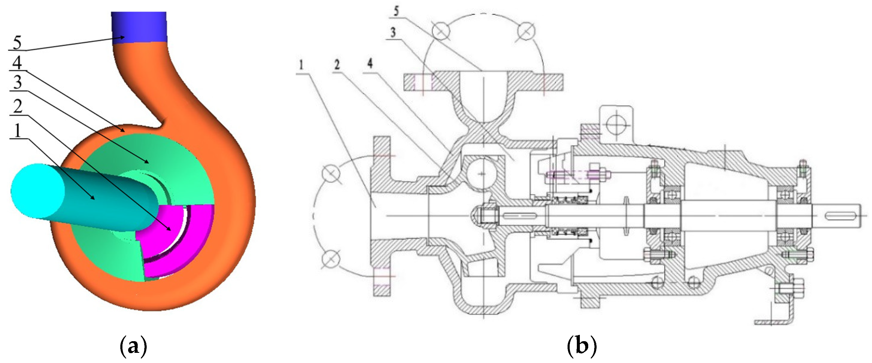
The calculation model in this paper is a 2.2 kW single-blade centrifugal pump. The main design parameters are as follows: flow rate Qd = 20 m3/h, head H = 11 m, rotation speed n = 2940 r/min, and specific speed ns = 132. The main geometric parameters are as follows: impeller inlet diameter Dj = 45 mm, outlet diameter D2 = 125 mm, outlet width b2 = 30 mm, blade angle φ = 360°, and volute base circle diameter D3 = 135 mm. Bladegen and Pro/E were used for the 3D modeling of the model. The model pump is shown in Figure 1, including the chamber, impeller, volute, inlet, and outlet sections. To ensure the stability of the numerical calculations, the extended inlet and outlet sections are five times the inlet and outlet diameters.
2.2. Meshing
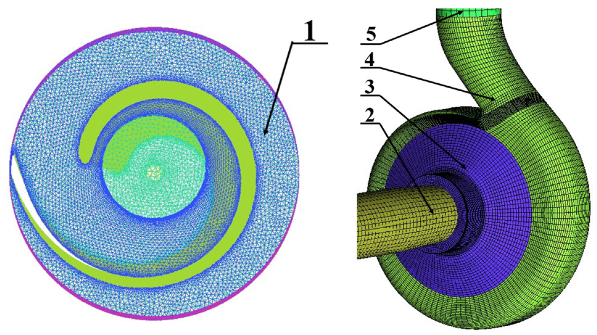
Meshing is the foundation of numerical calculation. The quality of meshing has the most direct impact on the accuracy and computational efficiency of numerical simulation. A 3D model is imported into ICEM for mesh generation. Since the structured grid sorting is simple and clear, has good controllability, and has good consistency with the flow direction of the fluid in the computational domain, the structured grid is mainly used. The pump chamber is a rotating geometry. In order to reduce the difficulty of mesh generation, the two-dimensional structural mesh generation is carried out first, and then the three-dimensional mesh is obtained by rotation. Then the distribution of nodes at the ends of the edge is adjusted to obtain the boundary layer. The structured grid cannot guarantee its orthogonality because the blade angle of a single-blade centrifugal pump is large and the distortion at the inlet is serious. The impeller adopts a tetrahedral unstructured grid and the mesh of the near-wall boundary layer has been refined to improve mesh quality. As shown in Table 1, mesh independence was analyzed based on the head at the design flow rate. It can be seen that with the increase of the grid number, the head tends to be stable, and after the grid number reaches 1,457,264, the head hardly changes, and the change is less than 0.02. The final grid number is 2,727,422 with Y+ below 100 in all the computational domains. The calculation domains are shown in Figure 2.
2.3. Turbulence Model and Boundary Conditions
The basic governing equation is the Reynolds average Naiver Stokes (RANS) equation, the k-ε turbulence model is selected, and the SIMPLEC algorithm is used to calculate the coupling of velocity and pressure [20,21]. The scalable wall function is used to process the area near the wall [22]. The internal flow channel of a single-blade centrifugal pump is taken as the calculation domain, in which part of the impeller is set as the rotational domain and the other parts are set as the stationary domains, and the dynamic–static interface is set as the transient rotor–stator. Water at a temperature of 25 °C was used as the calculation medium, and the solid wall was set as the non-slip boundary conditions. Since the impeller and volute were the castings, their surface roughness was set to 50 μm. The inlet boundary condition was set as the mass flow rate with the turbulence strength at 5%. The pump outlet was set as a static pressure condition. The performance curve of the pump was obtained by changing the mass flow. The results of the steady simulation were used as the initial values of transient calculation. The time step of the transient calculation was set as 1.701 × 10⁻⁴ s (3° per time step) for the simulation. Ten revolutions were calculated and the total time was 2.011 × 10⁻¹ s. The convergence accuracy was set as 10−5.
3. Experimental Verification
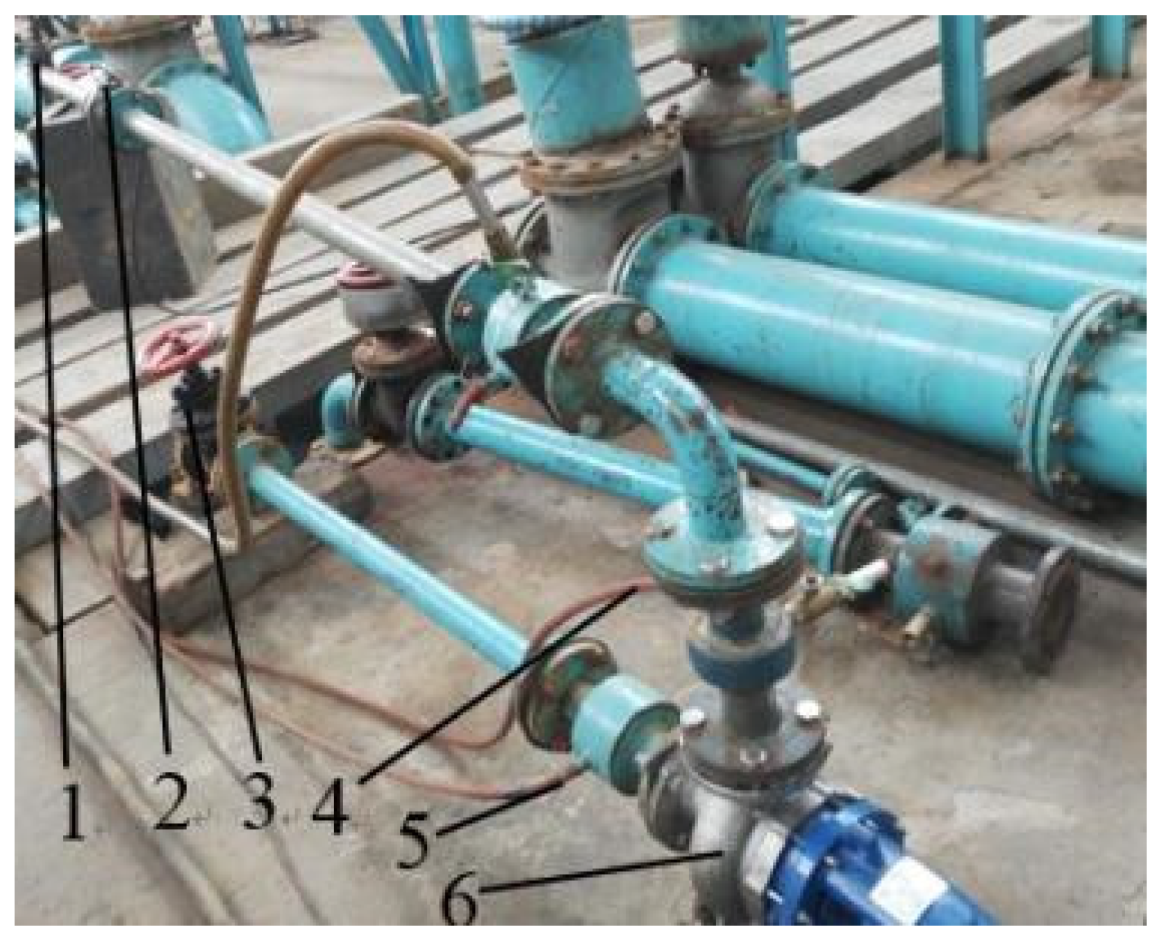
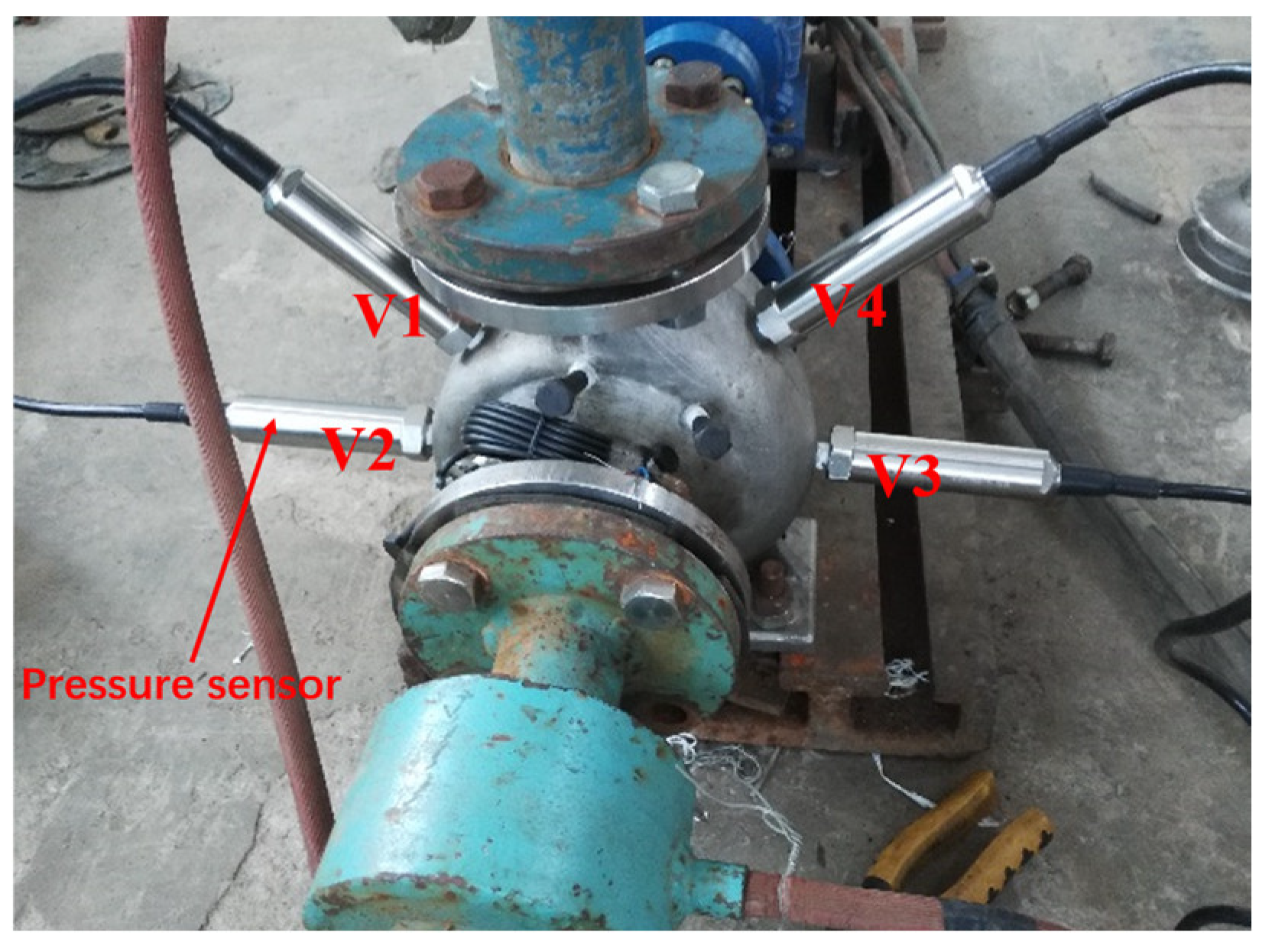
The pump performance experimental setup and distribution of pressure sensors are shown in Figure 3 and Figure 4. The experiment device consists of the test pump, connecting pip, electromagnetic flowmeter, and others. The distribution positions of four pressure sensors are shown in the Figure 4, which provided the absolute pressure values with an uncertainty of less than 0.1%. Due to the residual uncertainty of the experimental instruments, methods, and uncontrolled test conditions in the measurement system, the uncertainty of the head, pressure, and flow rate was ±0.524%, ±0.571%, and ±0.352%, respectively, and the total uncertainty was ±0.747%. The measurement accuracy of the test system reached Chinese national accuracy level II.
3.1. External Characteristic Verification
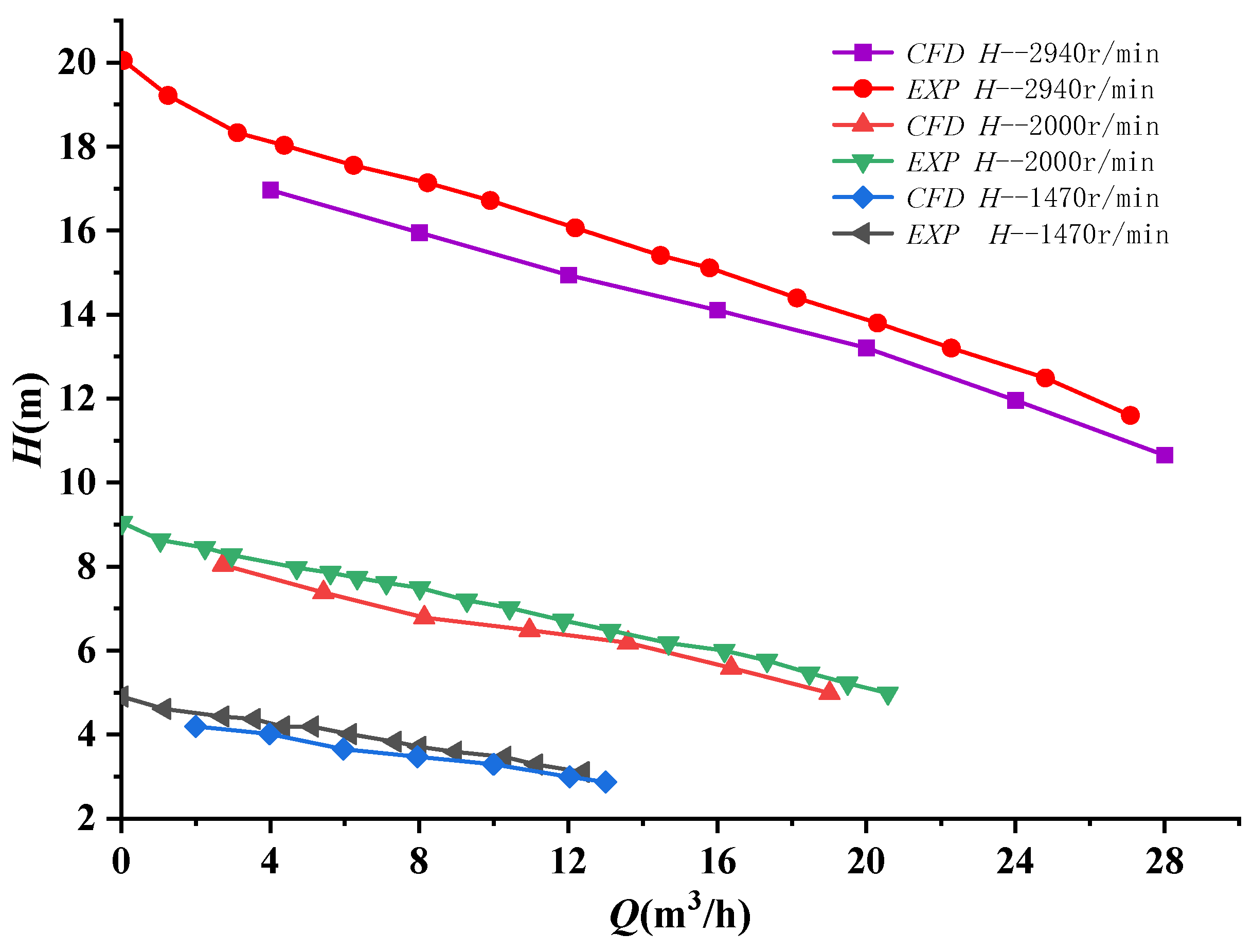
During the test, the inlet valve was kept fully open and the flow was changed by adjusting the outlet valve. There were no less than 13 operating points being tested from the shut-off point to the large flow condition, and the three rotation-speeds of 1470 r/min, 2000 r/min, and 2940 r/min were tested, respectively. The Q-H curves obtained by the numerical simulation and experiment of the single-blade centrifugal pump with the non-eccentric impeller at different speeds are shown in Figure 5. It can be seen from the figure that the numerical simulation results at each rotation speed are basically consistent with the experimental results. However, because the flow field three-dimensional modeling will inevitably have a certain deviation from the actual operation of the pump, and there was a strong flow separation in the single-blade centrifugal pump, there was a certain deviation between the numerical simulation results and the test results. However, the error is basically maintained within 1m, indicating that the numerical simulation has a high calculation accuracy.
3.2. Pressure Distribution
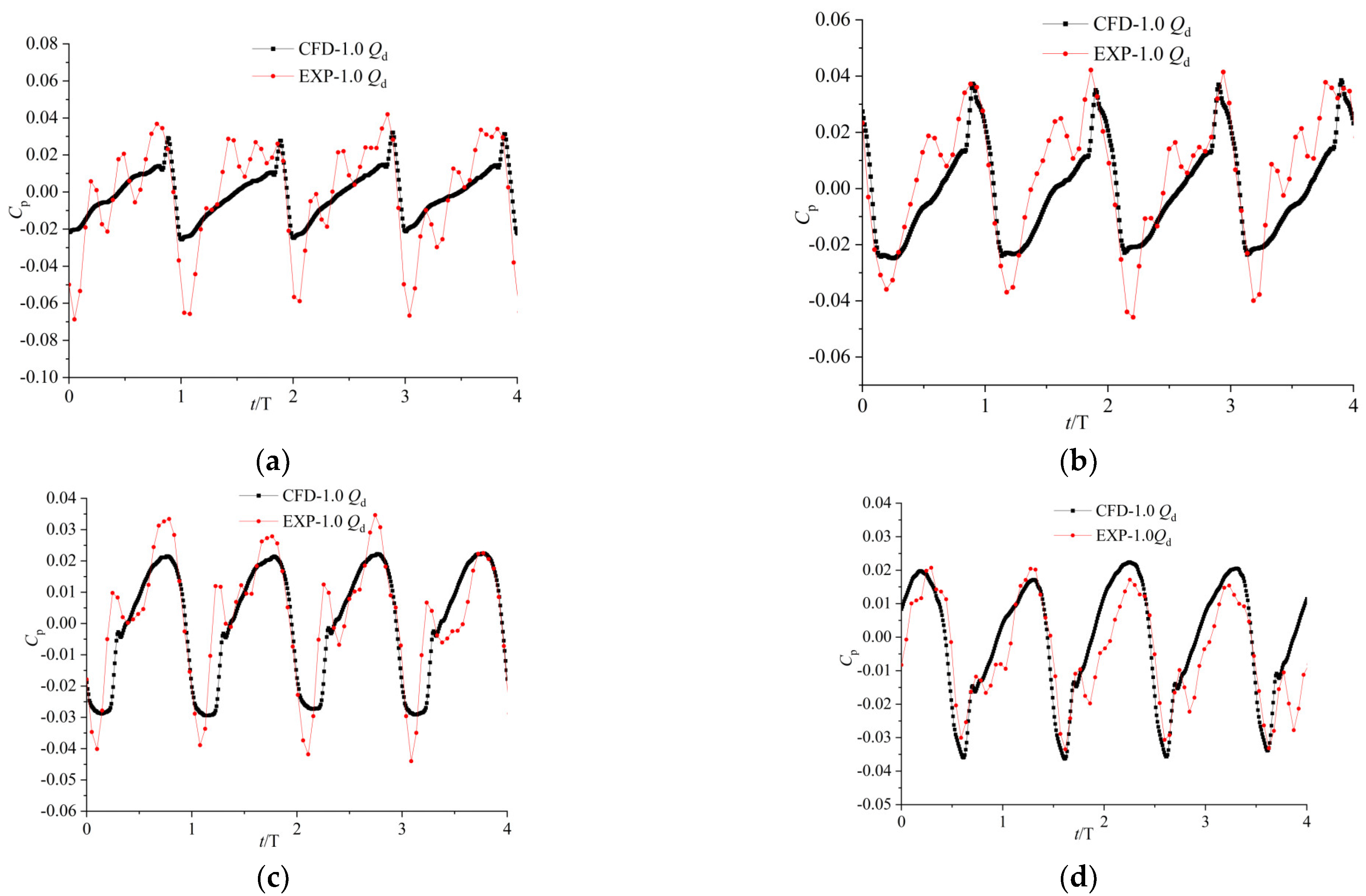
The comparison between the results of CFD and the experiment is presented in Figure 6 [11]. From the figure, we can find that the trend of the results is consistent. However, the pressure fluctuation of the experiment is more complex near the septum, and the amplitude of the pressure fluctuation of the numerical simulation is smaller. It may be that the flow in the pump at the tongue becomes more complex, and the turbulence model and wall function used cannot accurately capture these complex flow characteristics, resulting in some differences between the results of CFD and the experiment. However, in general, the numerical simulation can well predict the pressure pulsation in the pump, and the results have a certain accuracy and reliability.
From the above two groups of tests, it can be seen that there is some error between the test results and the numerical simulation results. Considering the uncertainty of the measurement system, this is inevitable. However, the change trend is basically the same, indicating that the numerical simulation has high accuracy.
4. Results and Analysis of Numerical Calculation
4.1. Influence of Impeller Eccentricity on Radial Force
The single-blade centrifugal pump has only one blade with a large wrap angle, and the impeller is an asymmetric structure, which will produce a large radial force during operation. The pressure and velocity distribution of the whole flow field in the pump can be obtained by a numerical calculation, and the radial force on the impeller can be obtained by integrating all the flow surfaces of the impeller. The integral result of a viscous force acting on the impeller surface is three orders of magnitude smaller than that of the pressure integral, so viscous force can be ignored in the calculation (1) [23]. The calculation formula of radial force in this paper is as follows:
where Fr is radial force and p is the pressure acting on the impeller surface A.
In this paper, the calculation model is simplified and ignores the dynamic characteristics of the eccentric motion of the impeller. The eccentricity and position of the impeller are fixed, and the influence of impeller eccentricity on the internal flow field and induced radial force of a single-blade centrifugal pump is analyzed by comparing the different eccentric positions and eccentricity size.
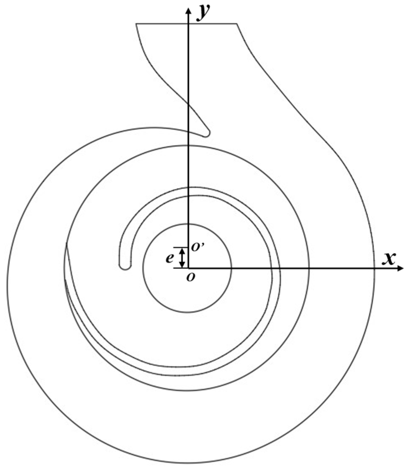
Figure 7 is the schematic diagram of the impeller eccentricity diagram, where the volute center O is located in the origin of coordinates and the impeller center O’ deviates from the coordinate center; e is the eccentricity. In the numerical calculation, four impeller eccentricity models, a, b, c, and d, with different circumferential positions are set, and the impeller center coordinates are (0,1), (−1,0), (0,−1), and (1,0), respectively, which represent the coordinates after the rotation center offset and values are in millimeters. At the same time, the calculation model e, with the impeller center position of (0,0.5), is set to compare the effects of different eccentricities.
The impeller pressure contour of the model with a non-eccentric impeller and model a at different times are shown in Figure 8. By comparison, it can be found that the flow field of a single-blade centrifugal pump is asymmetrically distributed around the circumference, and there is still a large radial force without eccentricity. The effect of small-scale impeller eccentricity on the circumferential distribution of the pressure field is not obvious. The pressure distribution in the pump at different moments with impeller eccentricity is similar to that without impeller eccentricity. Compared with ordinary centrifugal pumps, impeller eccentricity has less influence on the radial force of a single-blade centrifugal pump impeller.
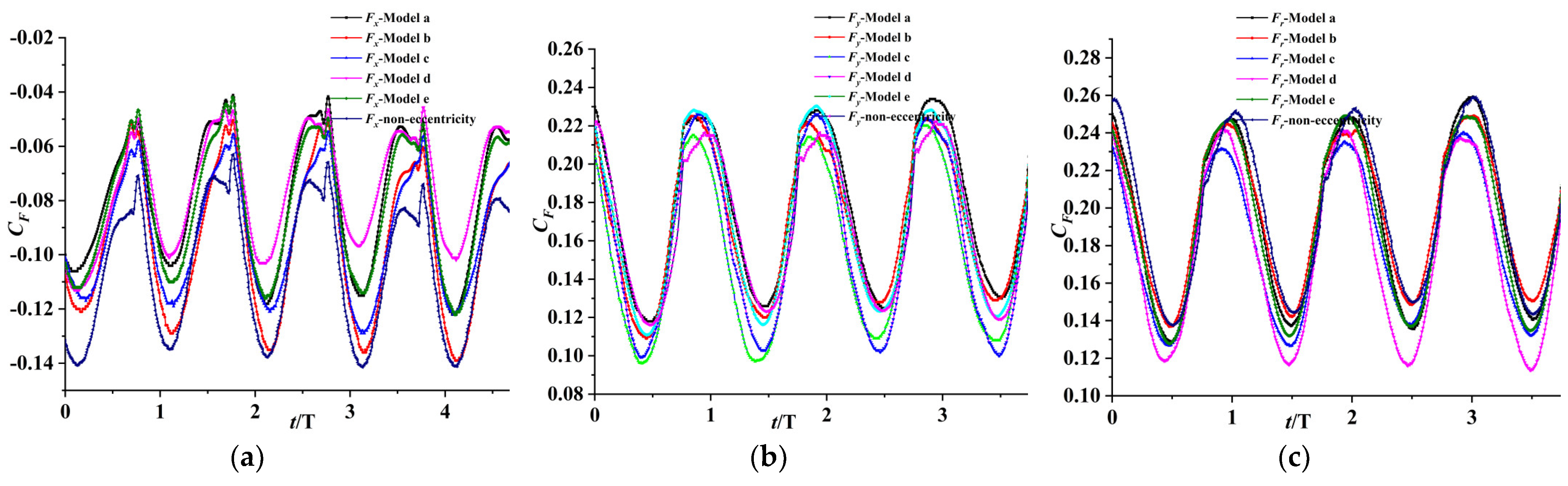
Figure 9 and Table 2 show the time domain diagram and time mean of radial force on the impeller of a single blade centrifugal pump under different impeller eccentricities. From Figure 9a, it can be seen that when the impeller eccentricity is different, from the rotation of the impeller, the variation trend of the radial force x component Fx is consistent. F is negative, and the time of the radial force peak and trough of each impeller is the same, without an obvious phase difference. The radial force x component is larger when the impeller is non-eccentric and the eccentricity is (−1,0), and the peak value of radial force is the largest and the pulsation is the strongest when the impeller eccentricity is (−1,0). When the shaft center of the impeller offsets 1 mm to the positive direction of the x-axis, that is, the eccentricity is (1,0), the x component radial force and pulsation are reduced to a certain extent, and the time average is reduced by 24% compared with the maximum value. When the impeller eccentricity is (0,1) and (0,0.5), the difference between the x component of the radial force is small. It can be seen from Figure 9b that eccentricity has little effect on the period and phase of the radial force y component Fy, but the radial force y component increases when the impeller shaft center is eccentric to the volute tongue. It can be seen from the graph that the Fy value is larger when the eccentricity is (0,1) than when the eccentricity is (0,0.5), the value is the largest, while the Fy value is the smallest, when the eccentricity is (0,−1), and the minimum value is 11% smaller than the mean value when at the maximum value. Viewing the fluctuation of Fy, the peak value is maximum when eccentricity is (0,1) and (−1,0). Figure 9c is the curve of a radial force varying with time. The diagram shows that impeller eccentricity has little effect on the period and peak phase of radial force. When the impeller eccentricity is (1,0), the radial force is the smallest, and the mean value is reduced by 8.8% compared with the maximum value, but the peak value is increased compared with the non-eccentric impeller, which means that the impeller eccentricity leads to the increase of radial force pulsation.
In general, when the impeller eccentricity is located at different circumferential positions and different eccentricities, the radial force on the impeller of a single blade centrifugal pump is different. The impeller close to the tongue will lead to the increase of radial force, the offset of the impeller center to the positive direction of the x-axis, and the negative direction of the y-axis helps to reduce the radial force. This means that the increase of the gap between the impeller and volute tongue is beneficial to reduce the radial force [24].
4.2. Balance Radial Force through Impeller Eccentricity
From the above analysis, it can be seen that the radial force of the impeller can be reduced by shifting the impeller to the x positive direction or y negative direction. In this paper, the radial force of the impeller is balanced by an appropriate offset to the fourth quadrant. The differential value between impeller diameter and volute diameter is 10 mm, that is, the unilateral clearance is only 5 mm. The setting coordinates (2,−2), as the impeller eccentric position, try to find a better impeller center position. Due to the small gap between the wear ring and the impeller, the large impeller eccentricity will lead to interference between the impeller and the wear ring. Therefore, the corresponding eccentricity of the pump inlet should be made after getting a better impeller position.
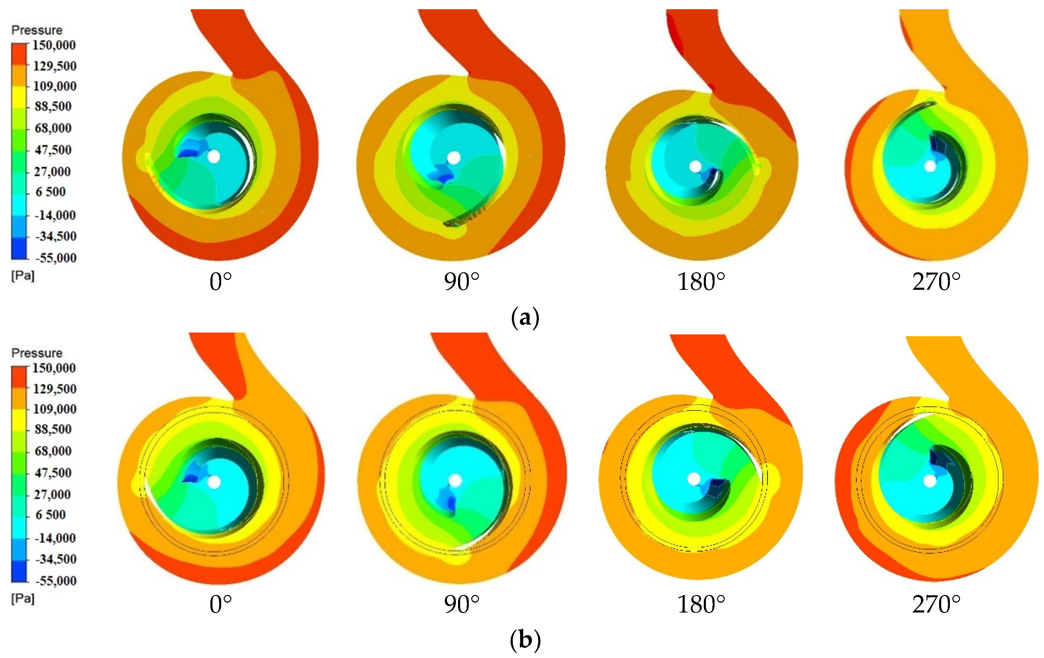
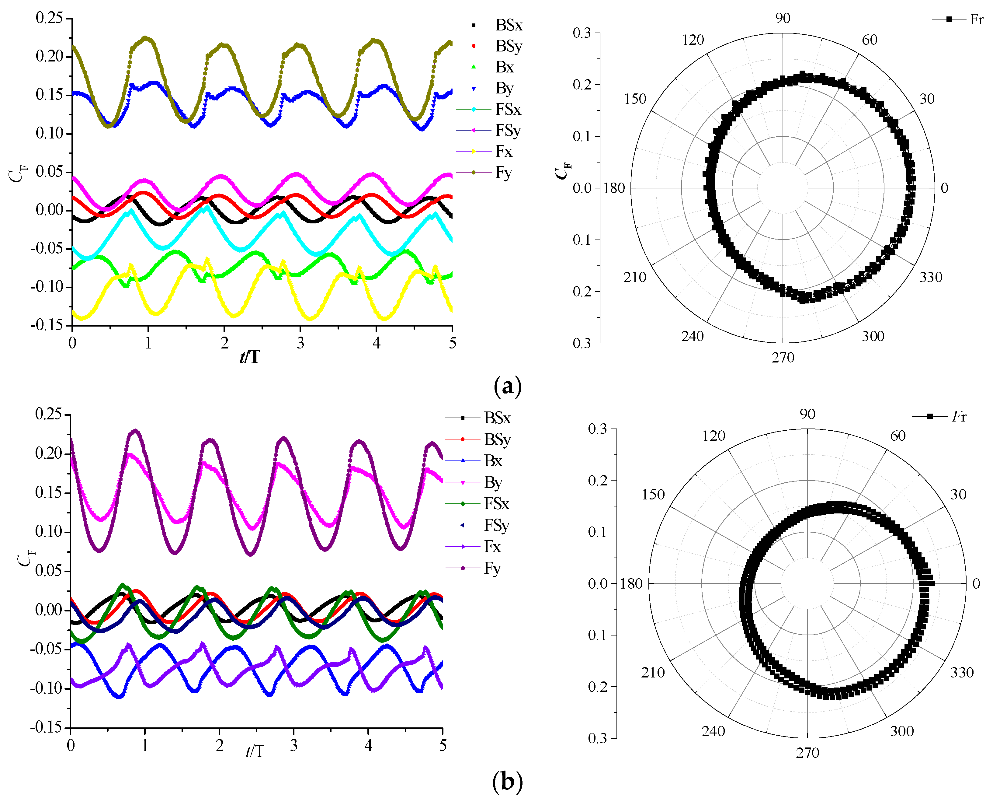
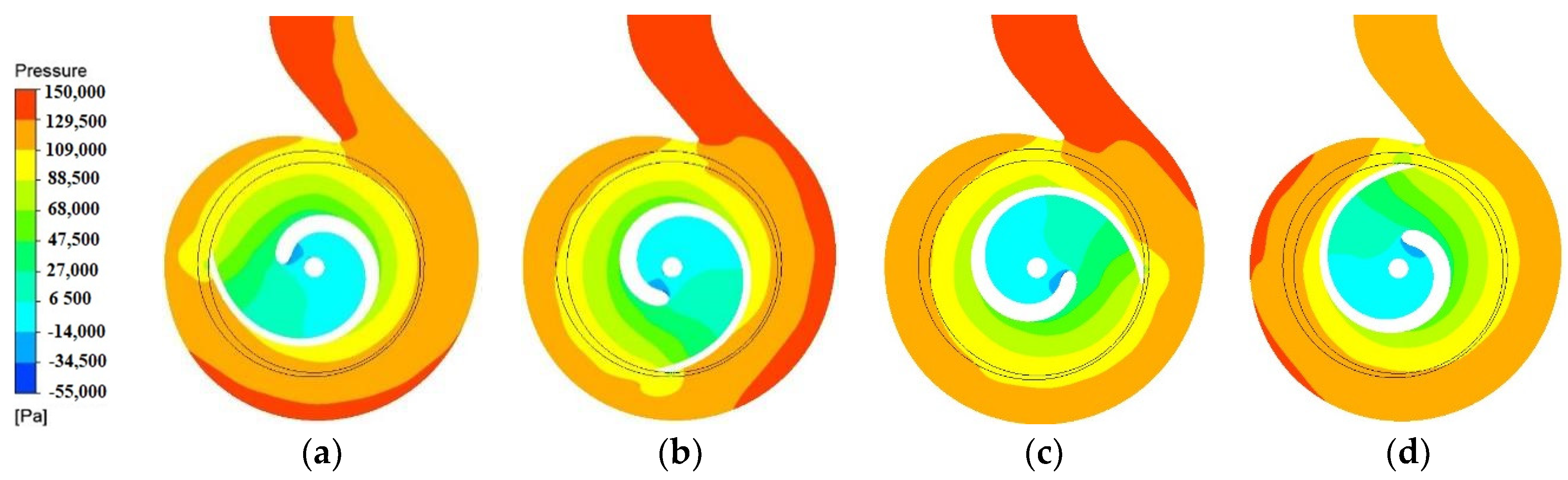
The radial force acting on the impeller at the rated flow rate is shown in Figure 10 (in the figure, BS represents the back cover, FS represents the front cover, and B represents the blade). It can be seen from the figure that the time–domain diagram of the radial force on the impeller after eccentricity is similar to that without eccentricity. However, the radial force on the front cover of the impeller is reduced, and the radial force on the impeller is also reduced. Figure 11 shows the pressure contours of a single-blade centrifugal pump at different times of underrated flow conditions under eccentric conditions. By comparing with Figure 6a, it can be found that the pressure distribution in the pump is similar at different moments, which is circumferentially asymmetric. However, when the impeller rotates at 0° and 90°, the impeller eccentricity (2,−2) decreases the high-pressure area in the positive x-direction of the volute, and the symmetry of the pressure distribution in the pump is improved. Therefore, the x component of the radial force decreases obviously when eccentricity is (2,−2).
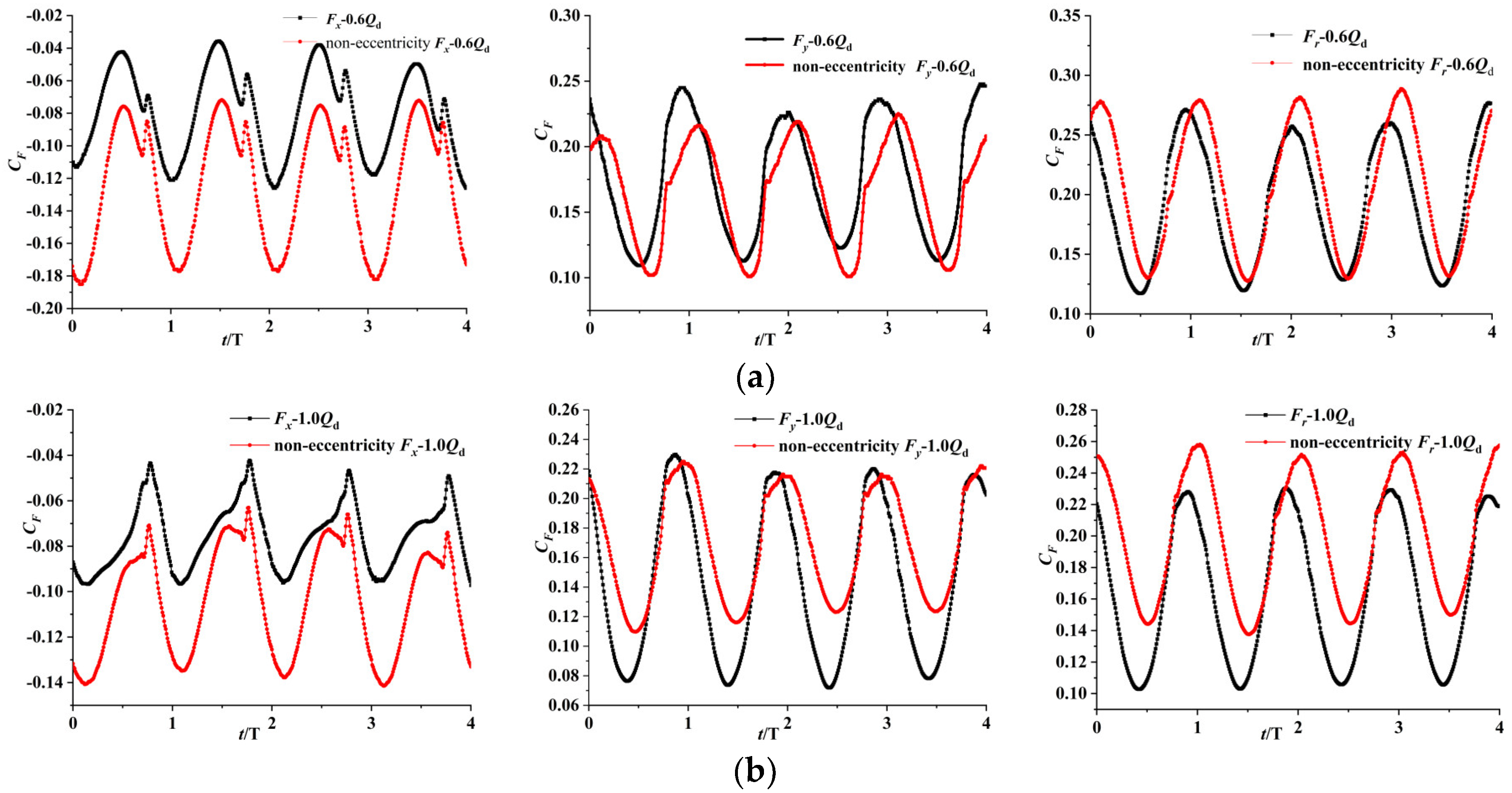
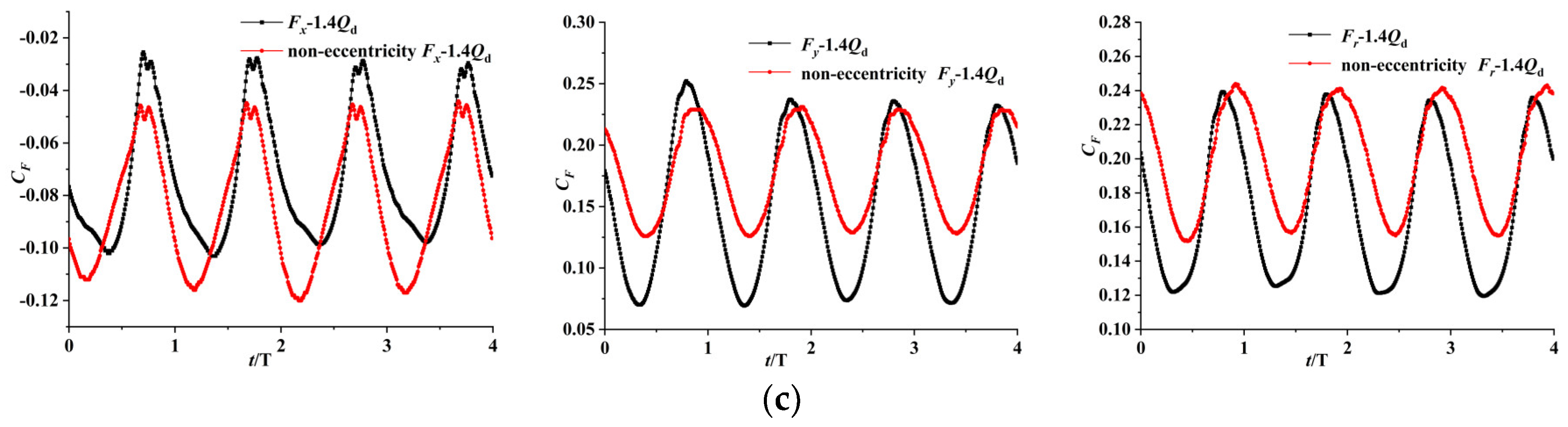
Figure 12 and Table 3 show the comparison of radial force on impeller eccentricity (2,−2) and non-eccentricity under different flow conditions. The radial force x component Fx of an eccentric impeller is significantly reduced, the time-averaged value is 35% lower than that of a non-eccentric impeller, but the radial force y component Fy changes little, the radial force Fr decreases, and the time-averaged value decreases by 6% at a low flow rate, which is 0.6 Qd. When the flow rate is 1.0 Qd, the reduction effect of the radial force of the eccentric impeller is more obvious, in which the time-averaged value of the x component Fx is 27.5% lower than that of the non-eccentric impeller. The peak value of the radial force y component Fy wave is similar, but the trough value is significantly reduced, with the time-averaged value reduced by 14.7% and the time-averaged value of the radial force Fr reduced by 17%. When the flow rate is 1.4 Qd, the x component Fx decreases significantly, and the mean value is 11.4% lower than that of the non-eccentric impeller. The peak value of the radial force y component Fy increases significantly, the mean value of Fy decreases by 15.8%, and the mean value of the radial force Fr decreases by 12.5%.
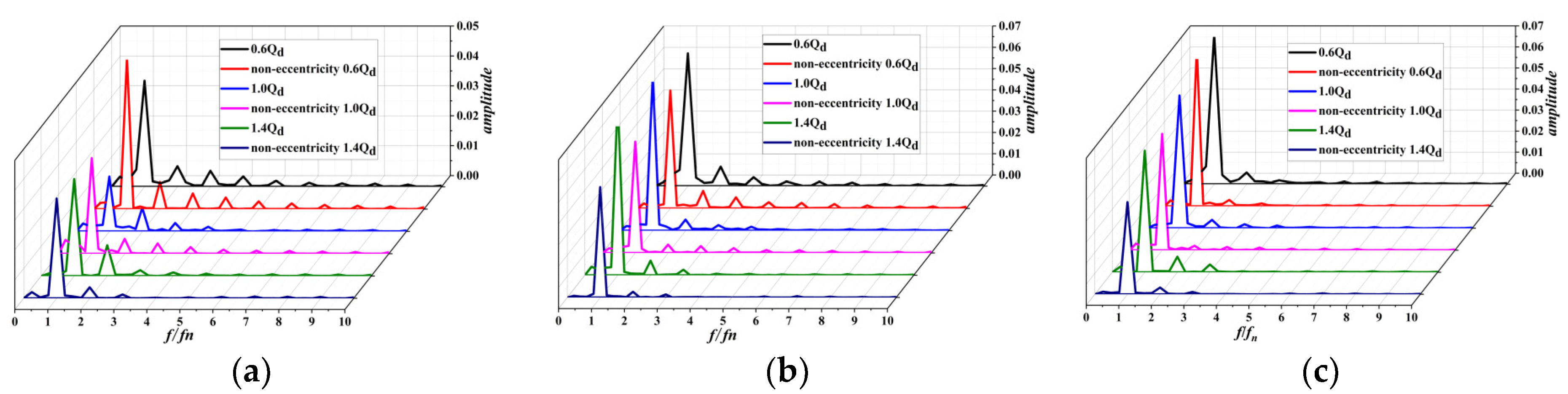
Figure 13 is the frequency domain diagram of radial force on the impeller with eccentricity and non-eccentricity under different flow conditions at a rated speed. It can be seen from the figure that the radial force on the impeller only has a large amplitude at the rotational frequency and harmonic frequency of the impeller, and the maximum amplitude occurs at the impeller rotational frequency. Therefore, the dominant frequency of the radial force on the impeller is its rotational frequency. It can be seen from Figure 13c that due to the intensification of flow separation under small flow conditions, the amplitude of the radial force fluctuation on the impeller is the largest. On the other hand, comparing the frequency domain diagrams with eccentricity and non-eccentricity, it can be found that the eccentricity of the impeller rotation center increases the amplitude of the radial force fluctuations.
The above comparative analysis shows that impeller eccentricity (2,−2) can effectively reduce the radial force of a single-blade centrifugal pump impeller under various flow conditions, as well as that the balance effect is more obvious in the radial force x-direction, the radial force y-direction can also be reduced, but the fluctuation is enhanced, and the balance effect is the best under the rated flow condition.
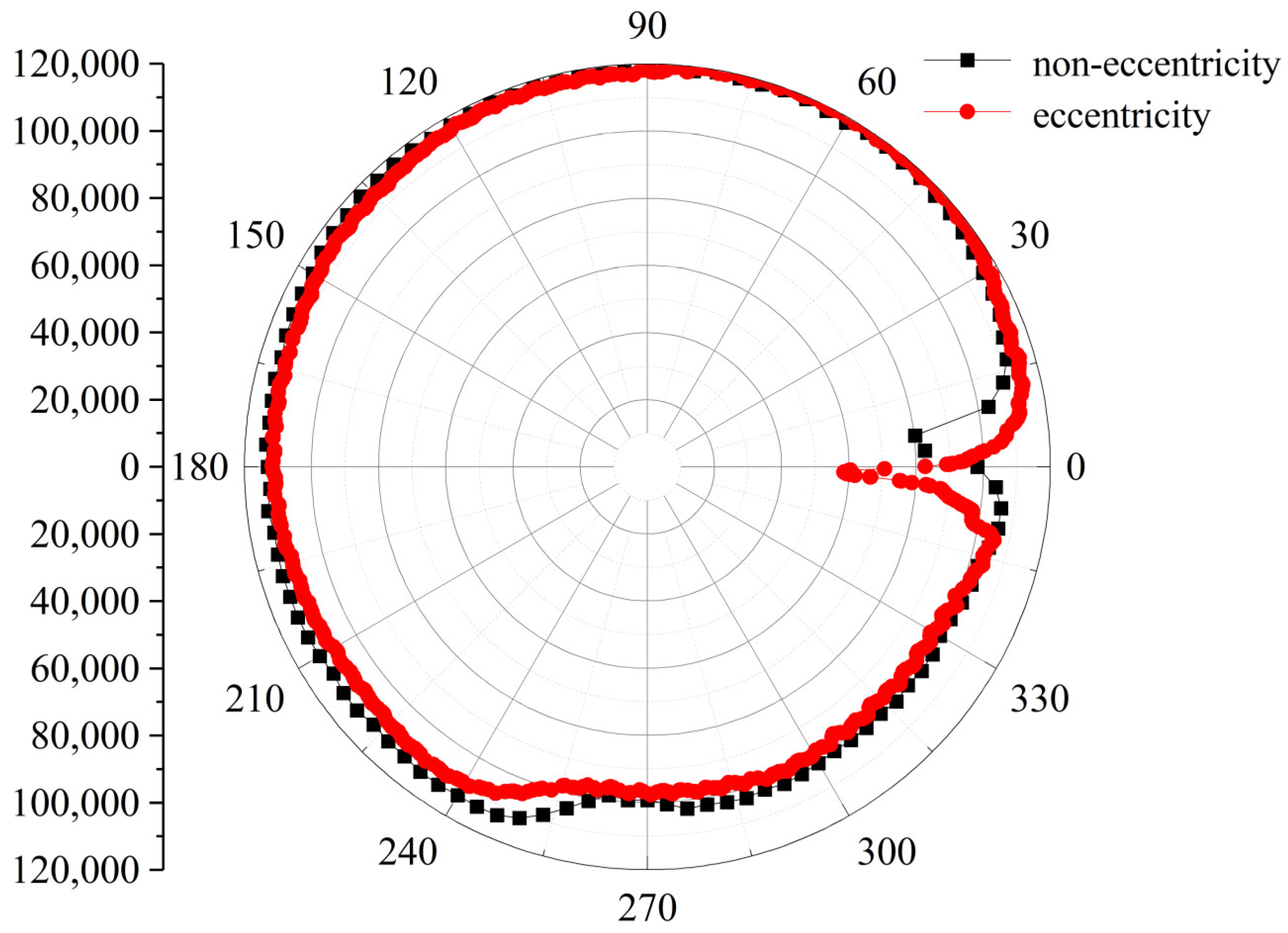
A comparison of the circumferential pressure distribution at the impeller outlet between impeller eccentricity (2,−2) and non-eccentricity is shown in Figure 14. It can be seen from the figure that the pressure decreases from the circumferential position 180° to the blade outlet after the impeller is eccentric. In this range, the clearance between impeller and volute increases after impeller eccentricity, which means that the increase in the clearance between the impeller and volute reduces the outlet pressure of the impeller, thus changing the circumferential distribution of pressure. This conclusion provides a reference for how to select the impeller eccentric position.
5. Conclusions
In this paper, the relationship between the radial force of the impeller and impeller center eccentricity is investigated on the basis of CFD simulation. The following conclusions were drawn on the basis of the aforementioned analyses:
- (1)
- Compared with the case without eccentricity, when the eccentricity coordinates of the impeller are (1,0) and (0,−1), the radial force on the impeller is reduced by 10.8% and 8.1%, respectively, which means the offset of the impeller center to the x-positive direction and y-negative direction can effectively reduce the radial force.
- (2)
- The hydraulically induced radial force of the impeller fluctuates periodically with the impeller rotation. The radial force varies with the impeller rotation, the curve being a distorted circle deviating from the center, and the radial force increases when the center of the impeller is close to the volute tongue.
- (3)
- The mean time of radial force on the impeller decreases after eccentricity (2,−2) under different conditions. It decreases by 17% under designed conditions 1.0 Qd, 12.5% under large flow conditions 1.4 Qd, and 6% under small flow conditions 0.6 Qd, which means the way is feasible.
In this paper, the eccentricity and fixed position of an impeller are studied and the dynamic characteristics of the eccentric motion of the impeller are ignored. In the future, we plan to use dynamic grid technology to deal with the flow field of eccentric clearance, and further study the influence of impeller eccentricity on the flow field and induced radial force in a single vane centrifugal pump.
Author Contributions
Data curation, C.C. and E.M.F.; Writing—original draft, C.W.; Writing—review and editing, L.T. and W.S. All authors have read and agreed to the published version of the manuscript.
Funding
This work was supported by the National Key R&D Program of China (Gran Nos. 2019YFB2005300), National High-tech Ship Scientific Research Project of China (Gran No. MC-202031-Z07), National Natural Science Foundation of China (Gran Nos. 52009013, 51979138, 52109106), China Postdoctoral Science Foundation (Grant No. 273746).
Conflicts of Interest
The authors declare no conflict of interest.
References
- Hirschberger, M.; Kuhlmann, J.; Benra, F.K. Designing high-power sewage water pumps. World Pumps 2009, 2009, 20–25. [Google Scholar] [CrossRef]
- Nishi, Y.; Fujiwara, R.; Fukutomi, J. Design method for single-blade centrifugal pump impeller. J. Fluid Sci. Technol. 2009, 4, 786–800. [Google Scholar] [CrossRef] [Green Version]
- Aoki, M. Instantaneous interblade pressure distributions and fluctuating radial thrust in a single-blade centrifugal pump. Bull. JSME 1984, 27, 2413–2420. [Google Scholar] [CrossRef]
- Nishi, Y.; Fukutomi, J. Effect of Blade Outlet Angle on Unsteady Hydrodynamic Force of Closed-Type Centrifugal Pump with Single Blade. Int. J. Rotating Mach. 2014, 2014, 1–16. [Google Scholar] [CrossRef] [Green Version]
- Meng, D.; Jiang, T.; Deng, H.; Hou, G. Numerical Simulation Research on Radial Force of Centrifugal Pump with Guide Vanes. Shock. Vib. 2021, 2021, 6638123. [Google Scholar] [CrossRef]
- Al-Obaidi, A.R. Influence of guide vanes on the flow fields and performance of axial pump under unsteady flow conditions: Numerical study. J. Mech. Eng. Sci. 2020, 14, 6570–6593. [Google Scholar] [CrossRef]
- Cui, B.; Li, J.; Zhang, C.; Zhang, Y. Analysis of Radial Force and Vibration Energy in a Centrifugal Pump. Math. Probl. Eng. 2020, 2020, 6080942. [Google Scholar] [CrossRef]
- Cui, B.; Li, X.; Rao, K.; Jia, X.; Nie, X. Analysis of unsteady radial forces of multistage centrifugal pump with double volute. Eng. Comput. 2018, 35, 1500–1511. [Google Scholar] [CrossRef]
- Jiang, W.; Li, G.; Liu, P.F.; Fu, L. Numerical investigation of influence of the clocking effect on the unsteady pressure fluctuations and radial forces in the centrifugal pump with vaned diffuser. Int. Commun. Heat Mass Transfer. 2016, 71, 164–171. [Google Scholar] [CrossRef]
- Cao, W.D.; Yao, L.J.; Liu, B.; Zhang, Y.N. The influence of impeller eccentricity on centrifugal pump. Adv. Mech. Eng. 2017, 9, 1687814017722496. [Google Scholar]
- Tan, L.W.; Yang, Y.F.; Shi, W.D.; Chen, C.; Xie, Z.S. Influence of Blade Wrap Angle on the Hydrodynamic Radial Force of Single Blade Centrifugal Pump. Appl. Sci. 2021, 11, 9052. [Google Scholar] [CrossRef]
- Chen, J.F.; Shi, W.D.; Zhang, D.S. Influence of blade inlet angle on the performance of a single blade centrifugal pump. Eng. Appl. Comput. Fluid Mech. 2021, 15, 462–475. [Google Scholar] [CrossRef]
- Al-Obaidi, A.R. Analysis of the Effect of Various Impeller Blade Angles on Characteristic of the Axial Pump with Pressure Fluctuations Based on Time- and Frequency-Domain Investigations. Iran. J. Sci. Technol. Trans. Mech. Eng. 2021, 45, 441–459. [Google Scholar] [CrossRef]
- Tan, L.; Shi, W.; Zhang, D.; Wang, C.; Zhou, L.; Mahmoud, E. Numerical and experimental investigations on the hydrodynamic radial force of single-channel pumps. J. Mech. Sci. Technol. 2018, 32, 4571–4581. [Google Scholar] [CrossRef]
- Zhou, R.; Yang, J.; Liu, H.L.; Dong, L. Effect of Volute Geometry on Radial Force Characteristics of Centrifugal Pump during Startup. J. Appl. Fluid Mech. 2022, 15, 25–36. [Google Scholar]
- Yuan, Y.; Yuan, S.Q.; Tang, L.D. Numerical Investigation on the Mechanism of Double-Volute Balancing Radial Hydraulic Force on the Centrifugal Pump. Processes 2019, 7, 689. [Google Scholar] [CrossRef] [Green Version]
- Hao, Y.; Tan, L. Symmetrical and unsymmetrical tip clearances on cavitation performance and radial force of a mixed flow pump as turbine at pump mode. Renew. Energy 2018, 127, 368–376. [Google Scholar] [CrossRef]
- Jia, X.; Yuan, S.; Zhu, Z.; Cui, B. Numerical study on instantaneous radial force of a centrifugal pump for different working conditions. Eng. Comput. 2020, 37, 458–480. [Google Scholar] [CrossRef]
- Al-Obaidi, A.R. Investigation of the influence of various numbers of impeller blades on internal flow field analysis and the pressure pulsation of an axial pump based on transient flow behaviour. Heat Transfer. 2020, 49, 2000–2024. [Google Scholar] [CrossRef]
- Xiaoqing, C.; Ri, Z.; Yongtao, H.; Dan-Qing, Y. Optimization Design of Deep—Well Centrifugal Pump based on CFX Orthogonal Test. Fluid Mach. 2015, 43, 22–25, (In Chinese with English abstract). [Google Scholar]
- Lang, T.; Shi, W.D.; Chen, K.Q.; Li, W.; Cheng, C. Research on the Flow Field and Abrasion Characteristics in Sewage Pump with Pre-mixing Device. Fluid Machinery 2015, 43, 29–33, (In Chinese with English abstract). [Google Scholar]
- ANSYS CFX Tutorials 14.5; ANSYS, Inc.: Canonsburg, PA, USA, 2012.
- Benenra, F.K.; Dohmen, H.J.; Schneider, O. Calculation of hydrodynamic forces and flow-induced vibrations of centrifugal sewage water pumps. Fluids Eng. Div. Summer Meet. 2003, 36975, 603–608. [Google Scholar]
- González, J.; Parrondo, J.; Santolaria, C.; Blanco, E. Steady and unsteady radial forces for a centrifugal pump with impeller to tongue gap variation. J. Fluids Eng. 2006, 128, 454–462. [Google Scholar] [CrossRef]
Figure 1.
Model pump. (a) Calculation domains. (b) Cross-section of the pump model. 1. Inlet, 2. Impeller, 3. Chamber, 4. Volute, 5. Outlet.
Figure 1.
Model pump. (a) Calculation domains. (b) Cross-section of the pump model. 1. Inlet, 2. Impeller, 3. Chamber, 4. Volute, 5. Outlet.

Figure 2.
Mesh of the pump. 1. Impeller, 2. Inlet, 3. Chamber, 4. Volute, 5. Outlet.

Figure 3.
Experiment setup. 1. Outlet valve, 2. Electromagnetic flowmeter, 3. Inlet valve, 4. Outlet pressure transducer, 5. Inlet pressure transducer, 6. Test pump.
Figure 3.
Experiment setup. 1. Outlet valve, 2. Electromagnetic flowmeter, 3. Inlet valve, 4. Outlet pressure transducer, 5. Inlet pressure transducer, 6. Test pump.

Figure 4.
Pressure sensors distribution.

Figure 5.
H-Q Curve Comparison.

Figure 6.
Comparison of pressure distribution at design flowrate. (a) Monitoring point V1. (b) Monitoring point V2. (c) Monitoring point V3. (d) Monitoring point V4.
Figure 6.
Comparison of pressure distribution at design flowrate. (a) Monitoring point V1. (b) Monitoring point V2. (c) Monitoring point V3. (d) Monitoring point V4.

Figure 7.
Diagram of the Eccentricity of the Impeller.

Figure 8.
Pressure contours at different moments. (a) When the impeller has no eccentricity. (b) Model a.
Figure 8.
Pressure contours at different moments. (a) When the impeller has no eccentricity. (b) Model a.

Figure 9.
Time–Domain Diagram of the Radial Force on the Impeller. (a) Radial force component in the x-direction; (b) Radial force component in the y-direction; (c) Radial force.
Figure 9.
Time–Domain Diagram of the Radial Force on the Impeller. (a) Radial force component in the x-direction; (b) Radial force component in the y-direction; (c) Radial force.

Figure 10.
The Radial Force on the Impeller at 1.0 Qd. (a) non-eccentricity; (b) impeller eccentricity (2,−2).
Figure 10.
The Radial Force on the Impeller at 1.0 Qd. (a) non-eccentricity; (b) impeller eccentricity (2,−2).

Figure 11.
Pressure contours at different moments when impeller eccentricity is (2,−2) and flow rate is 1.0 Qd. (a) 0°. (b) 90°. (c) 180°. (d) 270°.
Figure 11.
Pressure contours at different moments when impeller eccentricity is (2,−2) and flow rate is 1.0 Qd. (a) 0°. (b) 90°. (c) 180°. (d) 270°.

Figure 12.
Comparison of Radial Forces Under Different Operating Conditions. (a) 0.6 Qd. (b) 1.0 Qd. (c) 1.4 Qd.
Figure 12.
Comparison of Radial Forces Under Different Operating Conditions. (a) 0.6 Qd. (b) 1.0 Qd. (c) 1.4 Qd.


Figure 13.
Frequency domain diagram of radial force on impeller under different flow conditions at rated speed. (a). Fx. (b). Fy. (c) Fr.
Figure 13.
Frequency domain diagram of radial force on impeller under different flow conditions at rated speed. (a). Fx. (b). Fy. (c) Fr.

Figure 14.
Impeller Outlet Pressure Comparison.


Table 1.
Head of the pump at different grid number.
| Grid number | 618,866 | 1,162,332 | 1,457,264 | 2,727,422 | 2,899,675 |
| Head (m) | 12.38 | 12.35 | 12.18 | 12.20 | 12.19 |
Table 2.
The mean time of radial force on the impeller.
| Model a | Model b | Model c | Model d | Model e | Non-Eccentricity | |
|---|---|---|---|---|---|---|
| Fx | −0.0799 | −0.0953 | −0.0920 | −0.0755 | −0.0823 | −0.1047 |
| Fy | 0.1779 | 0.1720 | 0.1573 | 0.1631 | 0.1728 | 0.1702 |
| Fr | 0.1963 | 0.1988 | 0.1846 | 0.1812 | 0.1929 | 0.2008 |
Table 3.
Comparison of Radial Forces.
| 0.6 Qd | Non-Eccentricity 0.6 Qd | 1.0 Qd | Non-Eccentricity 1.0 Qd | 1.4 Qd | Non-Eccentricity 1.4 Qd | |
|---|---|---|---|---|---|---|
| Fx | −0.0801 | −0.1241 | −0.0759 | −0.1047 | −0.0738 | −0.0833 |
| Fy | 0.1784 | 0.1662 | 0.1452 | 0.1702 | 0.1505 | 0.1788 |
| Fr | 0.1961 | 0.2078 | 0.1664 | 0.2008 | 0.1747 | 0.1997 |
Publisher’s Note: MDPI stays neutral with regard to jurisdictional claims in published maps and institutional affiliations. |
© 2022 by the authors. Licensee MDPI, Basel, Switzerland. This article is an open access article distributed under the terms and conditions of the Creative Commons Attribution (CC BY) license (https://creativecommons.org/licenses/by/4.0/).
Share and Cite
MDPI and ACS Style
Wang, C.; Tan, L.; Shi, W.; Chen, C.; Francis, E.M. Research on Influence of Rotation Center Eccentricity on Radial Force of Single-Blade Centrifugal Pump. Water 2022, 14, 2252. https://doi.org/10.3390/w14142252
AMA Style
Wang C, Tan L, Shi W, Chen C, Francis EM. Research on Influence of Rotation Center Eccentricity on Radial Force of Single-Blade Centrifugal Pump. Water. 2022; 14(14):2252. https://doi.org/10.3390/w14142252
Chicago/Turabian StyleWang, Chuanlong, Linwei Tan, Weidong Shi, Cheng Chen, and Egbo Munachi Francis. 2022. "Research on Influence of Rotation Center Eccentricity on Radial Force of Single-Blade Centrifugal Pump" Water 14, no. 14: 2252. https://doi.org/10.3390/w14142252
Note that from the first issue of 2016, this journal uses article numbers instead of page numbers. See further details here.