
Research on the Relationship between Stall Propagation and Flange Leakage of Mixed-Flow Pumps


1
National Research Center of Pumps, Jiangsu University, Zhenjiang 212013, China
2
Institute of Fluid Engineering Equipment Technology, Jiangsu University, Zhenjiang 212009, China
*
Author to whom correspondence should be addressed.
Water 2022, 14(11), 1730; https://doi.org/10.3390/w14111730
Submission received: 28 April 2022
/
Revised: 24 May 2022
/
Accepted: 26 May 2022
/
Published: 28 May 2022
(This article belongs to the Special Issue CFD in Fluid Machinery Design and Optimization)
Abstract
:In order to explore the internal relationship between stall core propagation and flange leakage flow in the rotating stall of a mixed-flow pump, based on the k-ε turbulence model, a SIMPLEC algorithm and hexahedral structured grid are used to simulate the internal flow field of the mixed-flow pump. By setting the flange clearance as 0.2 mm, 0.5 mm and 0.8 mm, the propagation characteristics of the rotating stall and the unsteady characteristics of flange leakage flow of the mixed-flow pump under the condition of near stall are studied, and the influence of the flange clearance on the pressure fluctuation characteristics of the mixed-flow pump under the condition of near stall is analyzed. The results show that the stall core is located at the outlet of the impeller and propagates from the leading edge of the adjacent blade along the opposite direction of blade rotation to the next flow channel. The pressure gradient in the stall channel and the energy loss are large. When the flange clearance is 0.5 mm and 0.8 mm, the stall core changes from one to two, and the propagation mechanism of the stall core tends to be complex in the two adjacent flow channels. When the flange clearance is 0.8 mm, the propagation period decreases. The variation law of leakage flow is consistent with the propagation law of stall core. When the flow passage changes from stall state to non-stall state, the leakage flow also changes from one state to another, so the leakage flow can be used as a form of apparent stall. Under the condition of near stall, the pressure fluctuation curve of the adjacent monitoring points has a large phase difference consistent with the propagation period of the stall core, and has a strong pressure drop. When the flange clearance is 0.5 mm and 0.8 mm, the time domain curve of pressure fluctuation has two wave troughs in one cycle. In the near stall condition, the main frequency of the pressure fluctuation at the monitoring point is the stall frequency, and the amplitude of the main frequency at the middle of the outlet is the largest. The characteristics of flange leakage flow and pressure fluctuation can better reflect the flow situation in the pump when rotating stall occurs. The research results can provide a basis for judging whether stall occurs in the flow passage of the pump.
1. Introduction
As an excellent pump type, the mixed-flow pump has the advantages of both a centrifugal pump and an axial-flow pump, so it has been widely used in power engineering [1,2,3,4,5]. However, there is inevitably a gap between the blade flange and the runner chamber of the mixed-flow pump. Due to the relative motion between the blade flange and the end wall and the pressure difference between the pressure surface and the suction surface, the flange leakage flow occurs in the flange gap area. The mixing of the leakage flow and the mainstream of the suction surface will form the flange leakage vortex, which affects the stability of the pump [6,7,8,9]. The leakage flow interferes with the main flow, especially under the condition of small flow rate, at which the leakage vortex is more intense, which easily leads to flow instability such as rotating stall [10,11,12,13].
In the research of pumps, the phenomenon of unsteady flow induced by flange leakage has been concerned by some scholars. Inoue et al. [14] observed by PIV test that a characteristic circulation appeared in the region between the two blades at the top of the impeller near the head drop point and moved to the trailing edge of the blade. Sinha et al. [15] found that the flow velocity at the flange clearance is about 1.5 times of the impeller speed, and this high-speed leakage flow has an important impact on the occurrence of rotating stall. Goltz et al. [16] used high-speed photography to study the rotating stall phenomenon and observed the change of the shape and position of the clearance vortex. It is found that the state of vortex core in near stall condition is different from that in steady condition. Ma Yan et al. [17] conducted a full 3D viscous numerical simulation on the tip clearance of a small centrifugal impeller, and found that the increase in the tip clearance will expand the influence range of the leakage vortex, then lead to the deterioration of the impeller performance, and cause unsteady flow such as rotating stall.
In view of the influence of the flange clearance on the positive slope of the external characteristic curve of the mixed-flow pump, Li Xiaojun et al. [18] studied the occurrence and propagation mechanism of rotating stall in mixed-flow pump, analyzed the influence of inlet pre swirl, flange leakage vortex and guide vane inlet reflux on the positive slope curve, and found that when the positive slope occurs, there is a large-scale vortex at the outlet flange of the blade. Kim et al. [19] studied the influence of flange clearance on the head and efficiency of mixed-flow pumps, and found that the flange clearance has an important influence on the head curve, which is closely related to the appearance of saddle area. Li Yibin et al. [20] carried out numerical simulation on mixed-flow pump under different clearance, and found that when the clearance is 0.5 mm, the positive slope characteristic of head curve can be effectively suppressed. Li Wei et al. [21] studied the influence of tip clearance leakage flow on the rotating stall of mixed flow pump. The results showed that the stall was more likely to occur under small clearance, but the stall was more serious under large clearance. Goto [22] experimentally studied the influence of different flange clearances on the positive slope performance curve of mixed-flow pump with and without a cover plate, and considered that due to the influence of flange clearance, an open impeller is more likely to have positive slope characteristics than a closed impeller at small flow rates. Bart et al. [23] studied the relationship between the instability of the mixed-flow pump performance curve and hydrodynamic force under different clearances, and found that the increase in clearance has a great influence on the pump performance curve, as well as a certain relationship with the phenomenon of rotating stall. Masahiro et al. [24] studied the mixed-flow pump through the dynamic PIV test, and came to a similar conclusion. Zhang Rui [25] used the FBM-CC model to calculate the internal flow of the pump under different tip clearance, and found that under the same working condition, the larger the tip clearance is, the smaller the head is, and the pump performance curve has a positive slope. It is well known that the appearance of a positive slope curve is due to the occurrence of rotating stall.
In recent years, the pressure fluctuation of mixed-flow pumps under off design conditions has been paid attention by scholars at home and abroad. Jin shuanbao et al. [26] carried out numerical simulation on the internal flow field of mixed-flow pump, and found that with the decrease in flow rate, the pressure pulsation intensifies, and the pressure pulsation amplitude at the impeller inlet is the largest. At the same time, the pressure pulsation frequency at the impeller inlet and outlet is the impeller blade frequency, and the dominant frequency at the guide vane inlet and outlet changes with the change in flow rate. Yamade et al. [27] found through large eddy simulation that when the rotating stall occurs in the mixed-flow pump, the flow pattern inside the pump becomes very unstable, there is a local high-pressure area at the outlet flange of the impeller blade back, and the flow separation occurs. In the aspect of experimental research, Miyabe et al. [28,29] used a PIV test and numerical method to analyze the phenomenon of large-scale secondary reflux and vortex flow from the inlet of the guide vane to the outlet of the mixed-flow pump impeller under small flow conditions, and clarified that the rotating stall of the guide vane is the main reason for the unstable characteristics of the mixed-flow pump under small flow conditions. At the same time, the rotating stall at the inlet of the guide vane also makes the pressure pulsation fluctuate periodically. Zhang Desheng et al. [30] studied the internal pressure pulsation characteristics and laws of high specific speed mixed-flow pump under different working conditions by an experimental method. The results show that under different flow conditions, the amplitude of pressure pulsation from impeller inlet to guide vane outlet decreases in turn, and the periodic fluctuation of pressure pulsation also decreases in turn. Under the condition of small flow rate, the pressure fluctuation at the impeller outlet and guide vane outlet is relatively weak due to the influence of low-frequency large-scale vortex generated by flow separation and stall, tip leakage flow and backflow. Li Yibin et al. [31,32] studied the influence of dynamic and static interference on the internal pressure fluctuation characteristics of low specific-speed mixed-flow pumps by simulating the internal flow field. The results show that the amplitude of pressure fluctuation in the impeller and at the flange of the impeller outlet reaches the maximum, and the pressure fluctuation increases gradually from the impeller inlet to the guide vane outlet. When the rotating stall occurs in the mixed-flow pump, unstable vortices appear at the impeller inlet and cause the channel blockage. The vortices almost occupy the whole inlet channel, resulting in the deterioration of the inlet flow pattern. At present, there are many studies on the pressure pulsation in the pump at home and abroad, but the research on the pressure pulsation of the mixed-flow pump under stall condition is very rare.
The results show that the leakage flow is closely related to rotating stall and pressure fluctuation. However, in the existing literature, the research on the propagation characteristics of stall core and the unsteady characteristics of flange leakage flow of mixed-flow pumps is still insufficient. In this paper, the characteristics of rotating stall with different flange clearances under near stall condition are studied. The unsteady spatial structure and time characteristics of flange leakage flow and leakage vortex are analyzed. The internal relationship between rotating stall characteristics and flange leakage flow is explored. The influence of three kinds of near-stall conditions on the pressure pulsation of mixed-flow pump is studied by numerical simulation, the internal pressure fluctuation law of mixed-flow pump under stall conditions is revealed. This study can provide a new way for predicting early stall warning, restraining the instability of flow field, and has important reference value for the design and operation of mixed-flow pumps in large pumping stations.
2. Numerical Calculation Method
2.1. Design Parameters
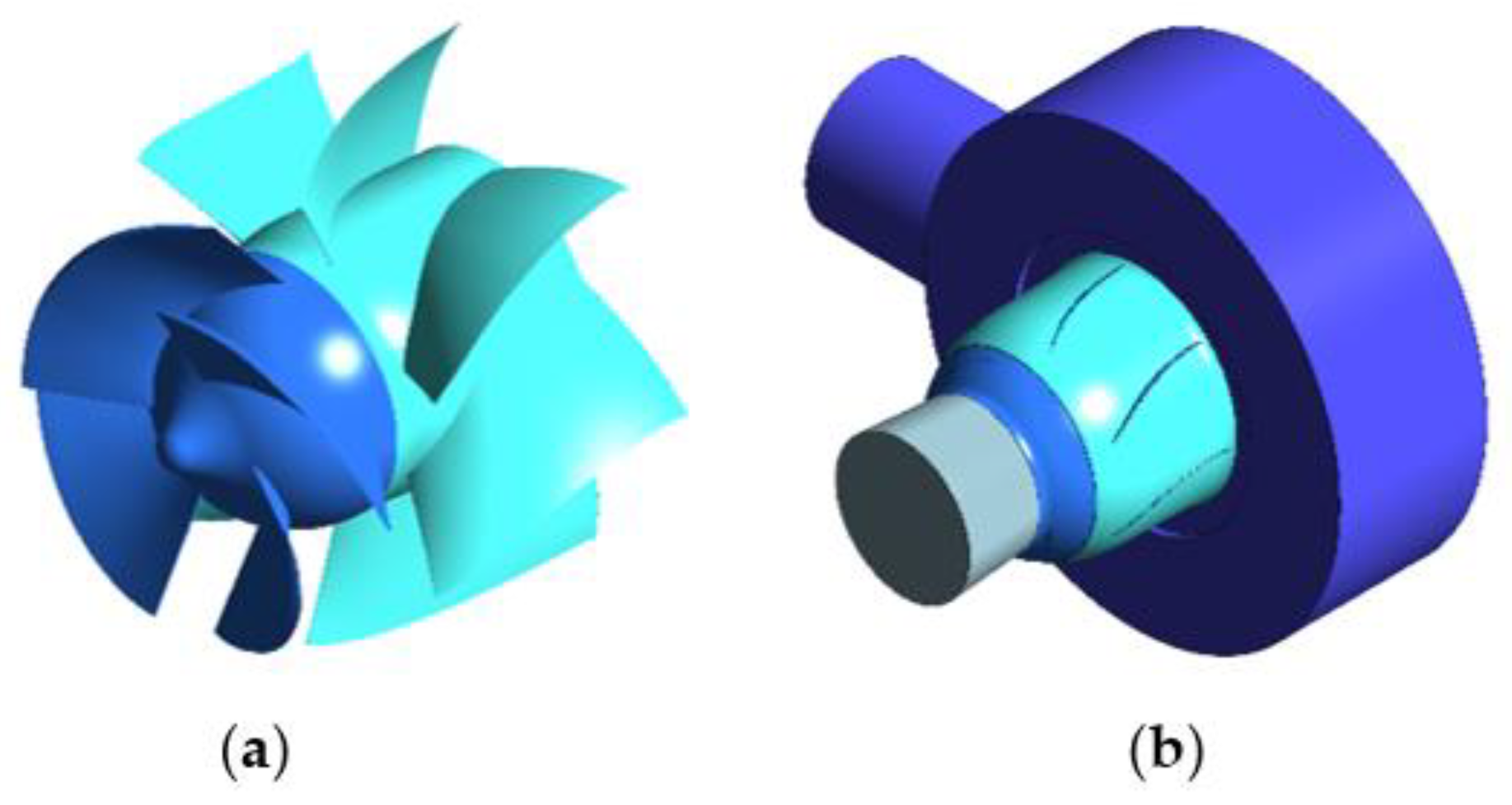
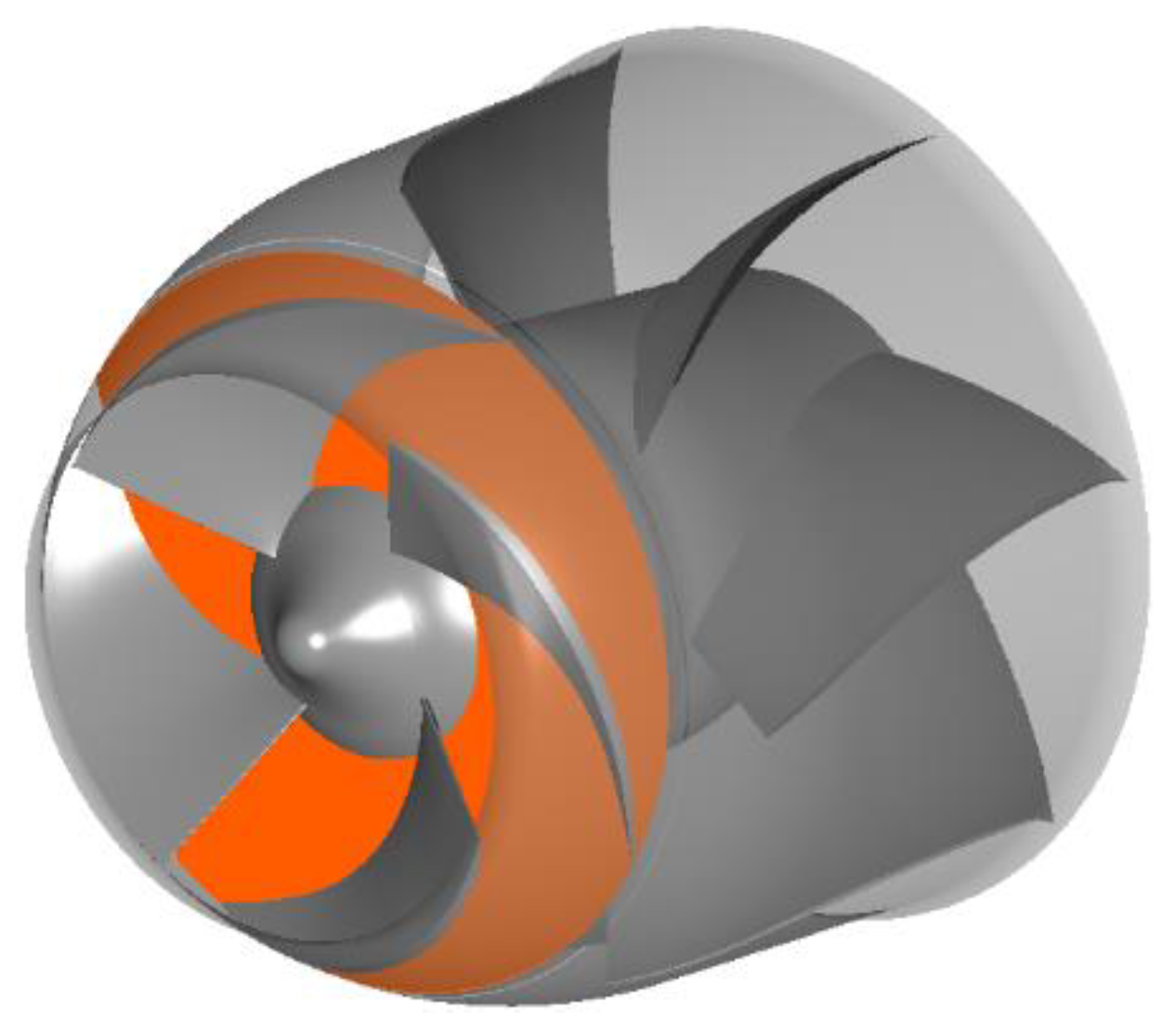
The main parameters of the guide vane mixed-flow pump studied in this paper are shown in Table 1, including the inlet section, impeller, guide vane, annular volute chamber and outlet section. The 3D modeling software Creo 5.0 is used to carry out the 3D modeling and divide the calculation domain, as shown in Figure 1. In the study, to keep the runner chamber size unchanged, the flange clearance was changed by changing the impeller diameter. The three groups of different flange clearances measured 0.2 mm, 0.5 mm and 0.8 mm, respectively.
2.2. Mesh Generation
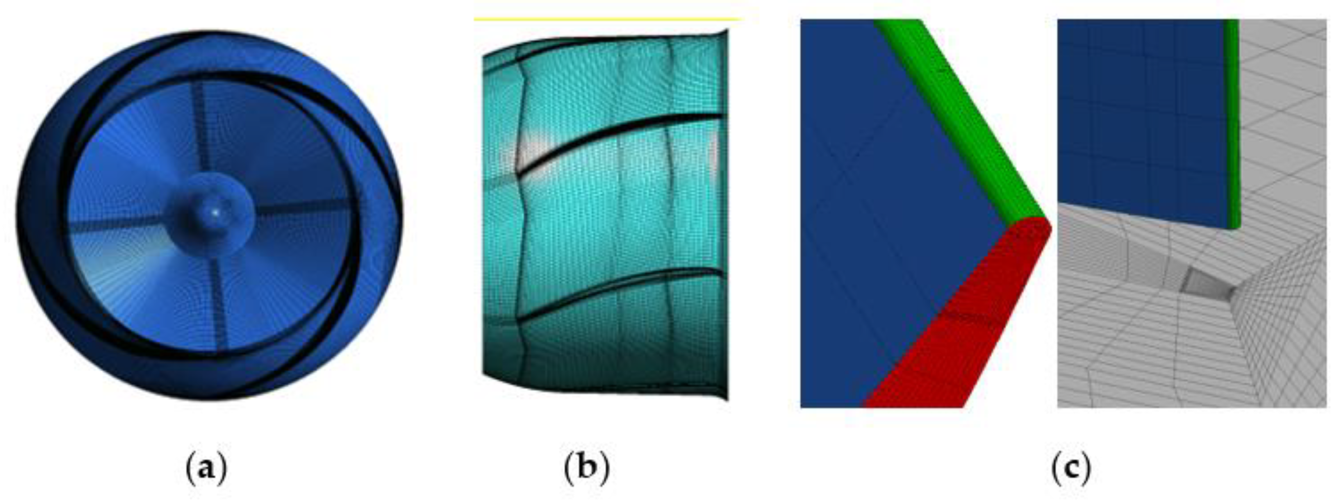
The quality of the mesh has a direct impact on the reliability of the calculation results, so ANSYS ICEM is used to divide each calculation domain into hexahedral structured meshes. Among them, the impeller adopts J/O topology and the guide vane adopts H/O topology. Because the flange clearance is very small compared with the impeller, to obtain high-quality mesh in the flange clearance area, the internal mesh in the flange clearance is encrypted by increasing the number of nodes, and the transition section from the clearance to the impeller is encrypted to ensure uniform transition. Finally, the quality of the structured grid of the impeller and guide vane water body after adjustment reaches more than 0.5, and the grid generation results are shown in Figure 2. The grid independence of the whole mixed-flow pump model is verified. It is found that when the number of global grids is close to 4.91 million, the head change of the mixed-flow pump calculated by increasing the number of grids by encrypting the grid is very small, and the relative error is within ±5%, as shown in Table 2, it meets the requirements of the grid independence test.
2.3. Turbulence Model and Boundary Conditions
The Reynolds average Naiver Stokes (RANS) equation is taken as the basic governing equation, the k-ε turbulence model is selected, and the equations are discretized by the finite volume method and SIMPLEC algorithm, and the second order upwind scheme is adopted. For the setting of boundary conditions, the inlet boundary adopts pressure inlet, the pressure value is 20 kPa, and the outlet boundary adopts mass flow outlet, which is set according to the change of flow. The front and rear interfaces of the impeller are dynamic and static interfaces, the interface mode in steady calculation is frozen rotor, the interface mode in unsteady calculation is transient rotor stator, and the other interfaces are static interfaces. The near wall is a non-slip wall, the wall function is automatic, the reference pressure is 1 atm, and the convergence accuracy is set to 10−5.
2.4. Experimental Verification of Simulation
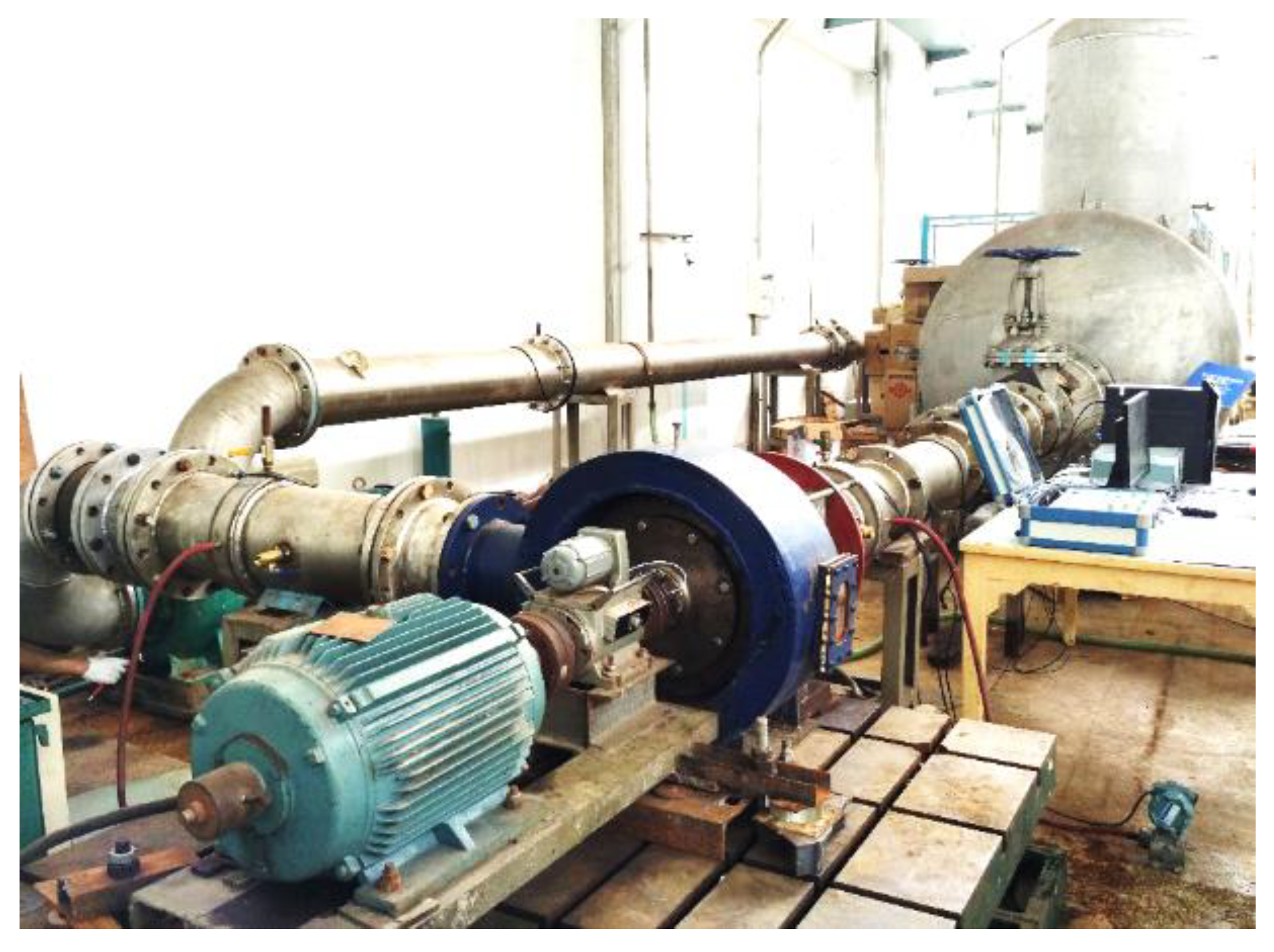
In order to verify the reliability of the numerical simulation method used in this paper, a mixed-flow pump test bench is built and the test system meets the accuracy requirements of level 1, as shown in Figure 3. Due to the limitations of the test conditions, the authors only measured the head and efficiency of the mixed-flow pump when the flange clearance was 0.5 mm and 0.8 mm, and compared them with the results of the numerical simulation.
Keeping the maximum opening of the inlet valve and slowly reducing the opening of the outlet valve, the parameters were measured under different flow conditions. The indications on the pump product parameter-measuring instrument and system analysis program were observed. When the indication was stable at a certain value or fluctuated back and forth within a small range of a certain value, it was considered to be the measured value, and the corresponding data were recorded. After the data measurement of the minimum flow condition was completed, the variable frequency regulator was still used to adjust the speed to slowly reduce it to zero. After the shutdown, we waited for the water flow in the pipeline to stand still, and then adjusted the opening of the outlet valve to the maximum again. In order to minimize accidental errors and improve the reliability of the test data, the energy characteristic data recorded in the three repeated tests were arithmetically averaged as the final test result.
The pump product parameter measuring instrument and the supporting pump product analysis and processing program can calculate the head of the test pump according to the inlet and outlet pressure of the test pipeline, calculate the shaft power according to the torque and speed data measured by the torque and speed measuring instrument, and calculate the efficiency according to the head and shaft power. The expressions of the three are as follows:
where P1 and P2 are pump inlet and outlet pressures respectively, Pa; Z1 and Z2 are the installation height of pump inlet and outlet respectively, m. v1 and v2 are the average flow velocity at the inlet and outlet of the pump, m/s; M is the measured torque of the pump, M0 is the no-load torque, N m; n is the speed, r/min; Q is flow, m3/h; H is the head, m; and P is the shaft power of the mixed-flow pump, kW.
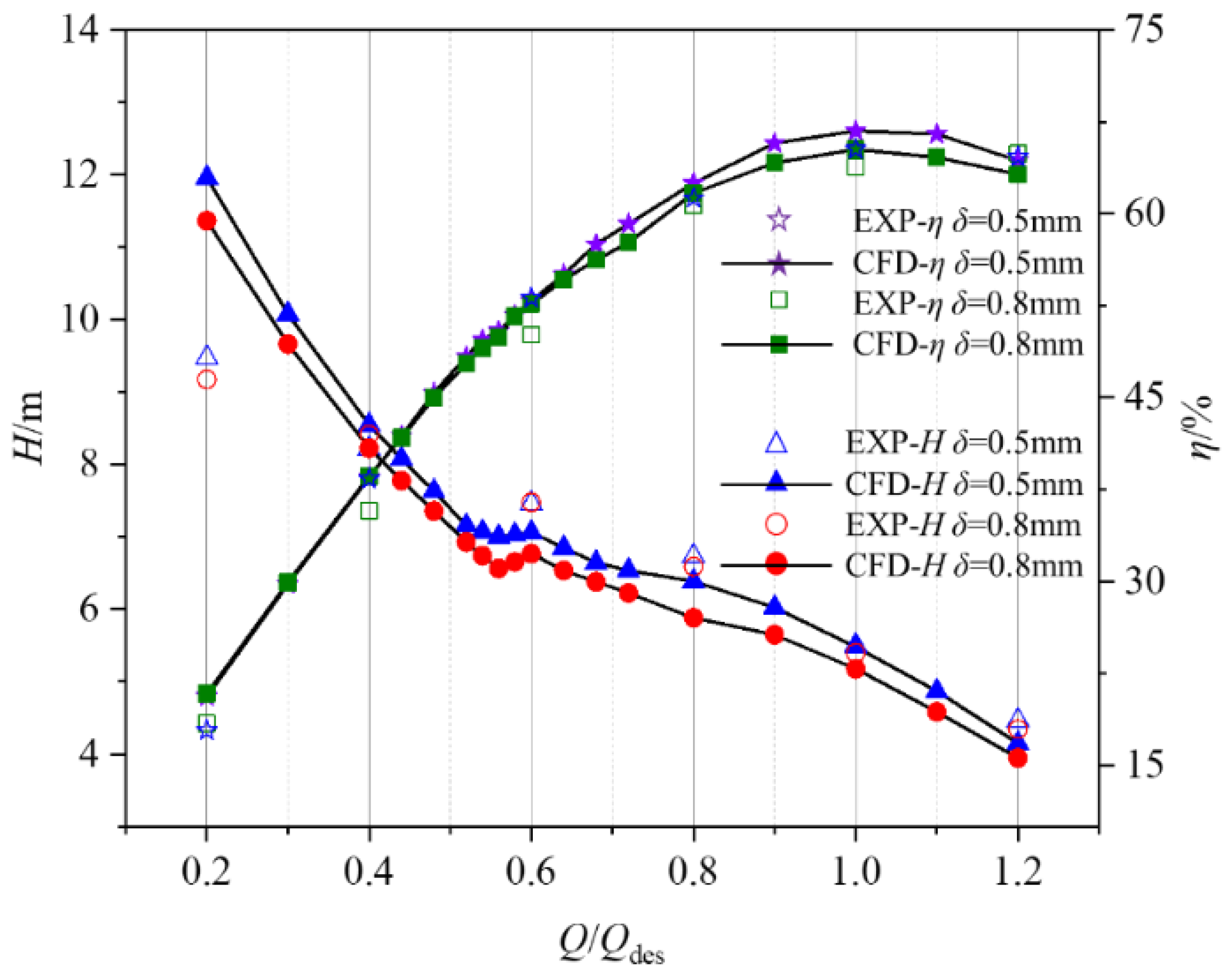
The comparison results of the external characteristics between the numerical calculation and the experimental measurement are shown in Figure 4. It can be seen from the figure that when the flange clearance is 0.8 mm, the H-Q (Head-Flow rate) curve of the mixed-flow pump presents an obvious positive slope near 0.6 Qdes (Qdes is the design flow rate). In the flow range from 0.4 Qdes to 1.2 Qdes, the numerical simulation results are basically consistent with the experimental results, only when the flow rate is low and the time difference is large. This is because when the flow rate is close to the critical point, the actual flow pattern is very complex, turbulent dissipation and impact loss are greater, and these factors cannot be fully covered in the numerical simulation. In addition, the simulation efficiency is slightly higher than the test efficiency because the friction loss is not fully considered. However, in general, the head and efficiency predicted by the numerical simulation are in good agreement with the experimental results, so the reliability of the simulation results is high.
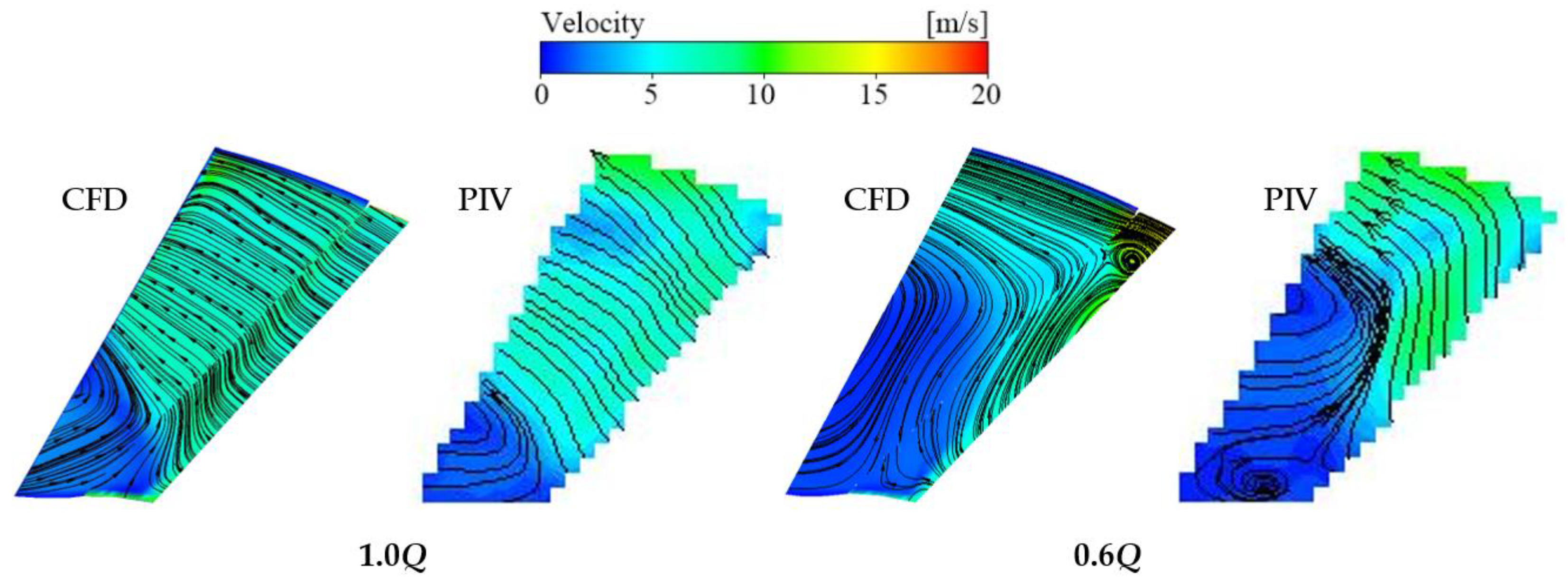
In order to more intuitively verify the accuracy of the numerical simulation method, the flow field structure in the dynamic and static interference area obtained by the numerical simulation in this paper is compared with the results of the PIV test carried out by our research group, as shown in Figure 5. It can be seen from the figure that although there are small differences under both design conditions and stall conditions, the CFD results of the flow field in the dynamic and static interference area are consistent with the PIV test results as a whole. This further illustrates the prediction accuracy of the numerical method.
3. Results and Discussion
3.1. Rotating Stall Characteristics under Near Stall Condition
With the decrease in the flow rate, the internal flow of the mixed-flow pump will become unstable and prone to rotating stall. Near stall is defined as the state when the mixed-flow pump just enters stall, that is, the working point when the head begins to decline. Firstly, the section of impeller outlet and guide vane inlet is analyzed, as shown in Figure 6.
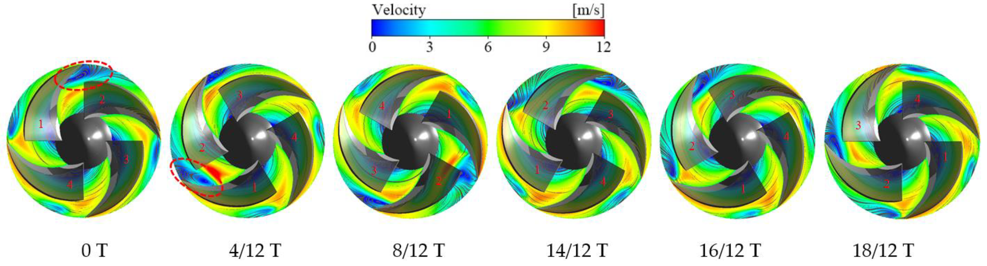
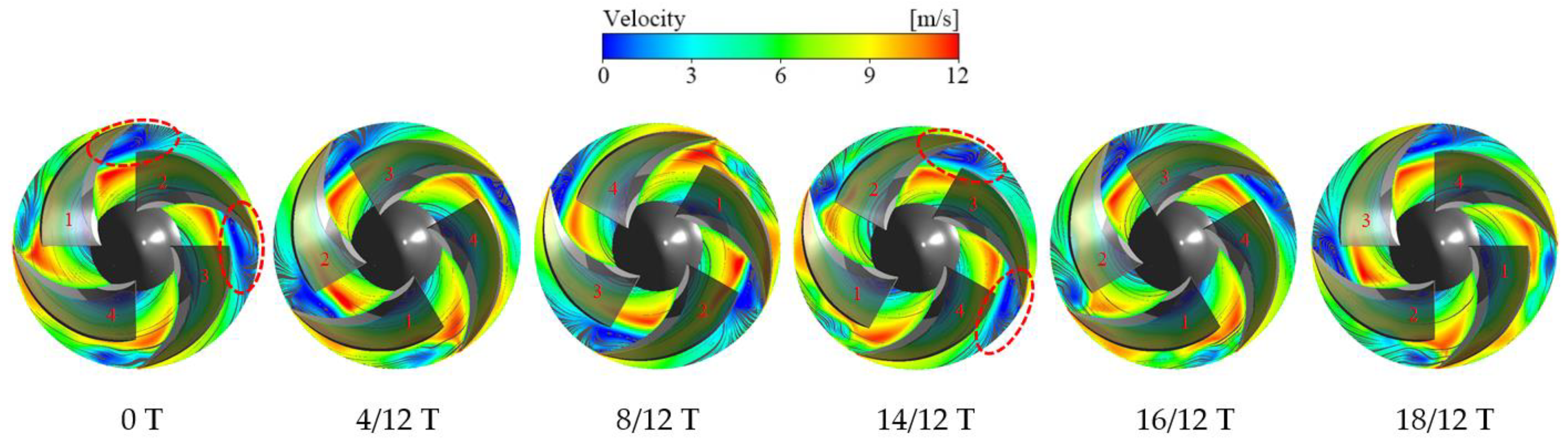
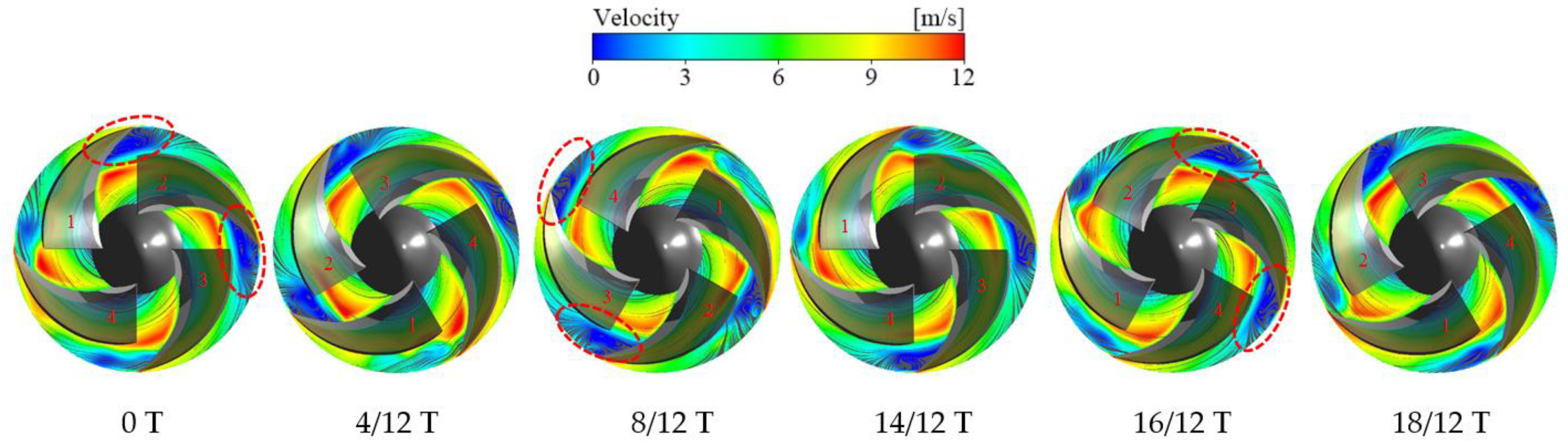
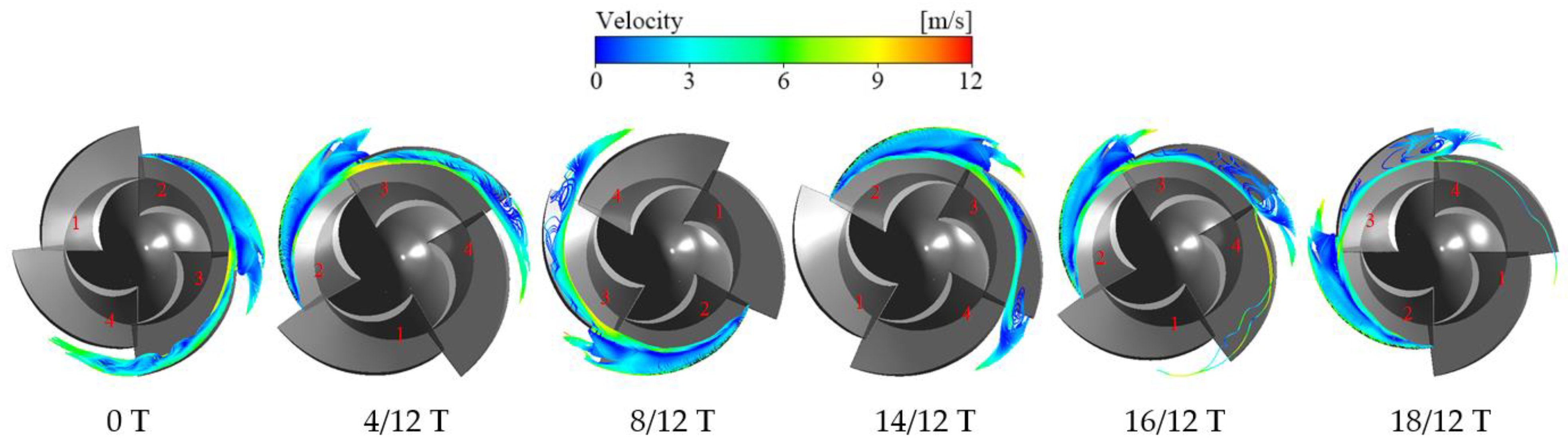
Figure 7 shows the velocity streamline of impeller outlet section at different times when δ = 0.2 mm under near stall condition. It can be seen from the figure that at 0 T, there is an obvious vortex at the outlet of the flow passage of blade 1, while the streamline at the outlet of the flow passage of blade 2 and blade 4 adjacent to blade 1 shows slight distortion, and the streamline at the outlet of the flow passage of blade 3 opposite blade 1 is the most stable. When the impeller rotates to 4/12 T, because the vortex at the outlet of blade 1 blocks the flow passage, the fluid can only shift to the pressure surface of blade 2, thus forming a high-speed region between the vortex and the pressure surface of blade 2. At the same time, the attack angle of blade 2 increases, the flow separation occurs in the flow passage, and the vortex begins to appear at the outlet. From 4/12 T to 14/12 T, the vortices at the outlet of the passage of blade 1 decrease gradually, while the vortices at the outlet of the passage of blade 2 increase gradually. When the impeller rotates to 14/12 T, the vortices at the outlet of the passage of blade 1 basically disappear, and there is only a certain distortion, while the vortices at the outlet of the passage of blade 2 gradually become obvious. From 14/12 T to 18/12 T, the distortion at the outlet of blade 1 is gradually reduced, and the vortex at the outlet of blade 2 is slightly enhanced. When the impeller rotates to 18/12 T, the vortex propagates from blade 1 to blade 2, completing a propagation cycle. From 0 T to 18/12 T, with the rotation of the impeller, the vortices develop and disappear in the flow passage of the impeller in turn, and propagate from the flow passage of blade 1 to the flow passage of blade 2. The propagation direction is clockwise, which is the opposite of the rotation direction of the impeller. According to the existing research results, it is judged that the rotating stall occurs in the pump, the vortex region is the stall core, and the propagation period of the stall core is about 18/12 T.
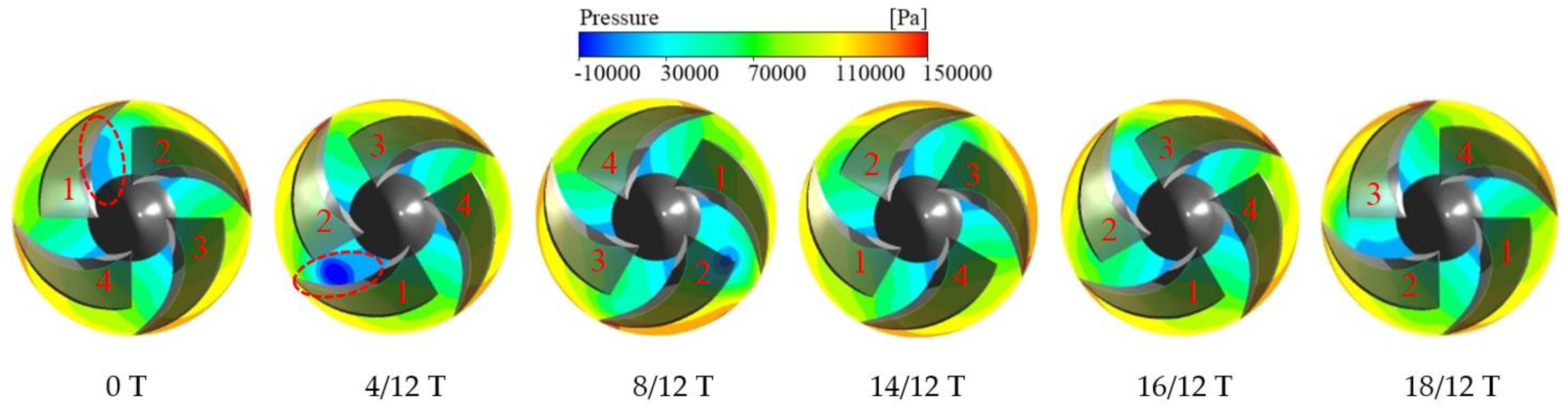
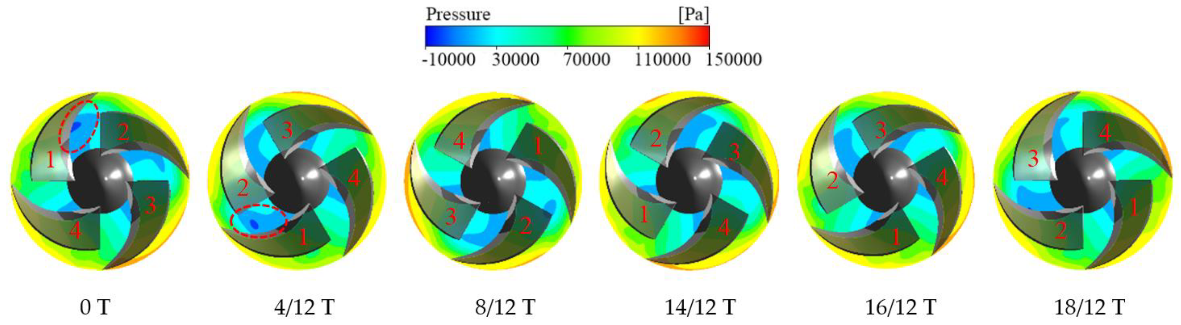
Figure 8 shows the pressure distribution of impeller outlet section at different times when δ = 0.2 mm under the same working conditions. It can be seen from the figure that at 0 T, there is an obvious low-pressure area near the inlet of blade suction surface, and the low-pressure area in blade 1 channel is much larger than the other 3 channels. The pressure gradient from inlet to outlet is obvious, which indicates that the channel with stall has a large pressure gradient. With the rotation of the impeller, the stall core begins to spread from the passage of blade 1 to the passage of blade 2. Correspondingly, the low-pressure region of the passage of blade 1 also changes. The low-pressure region of blade 1 begins to differentiate into an elliptical low-pressure region with lower pressure, and gradually moves away from the suction surface of blade 1 towards the pressure surface of blade 2 near the leading edge. Finally, stall occurs gradually in the passage of blade 2, and the pressure gradient in the passage increases, while the pressure distribution in the passage of blade 1 gradually becomes the same as that in the passage without stall. The propagation process of stall core in one cycle can be clearly seen from the change in pressure distribution in the channel, and there is a large pressure gradient in the channel where the stall core is located.
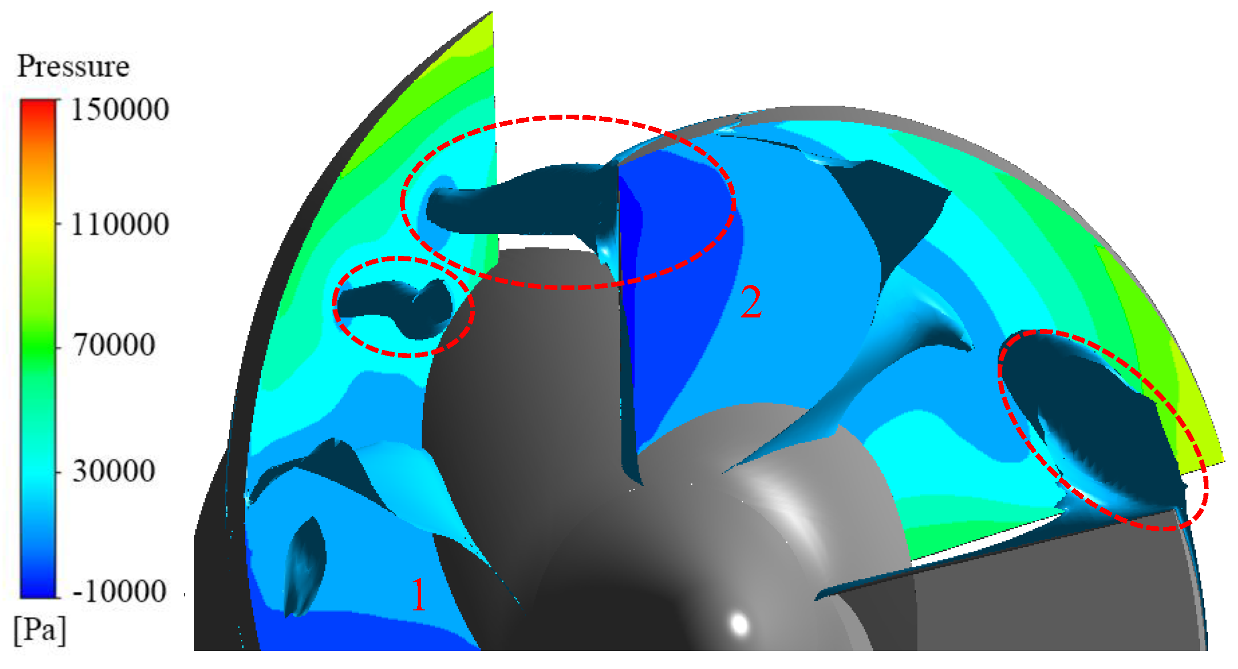
According to the velocity streamline diagram and pressure nephogram of the impeller outlet section, with the rotation of the impeller, the stall core and low-pressure area of blade 1 flow channel move towards blade 2 flow channel, then the stall core and low-pressure area of blade 1 flow channel disappear gradually, and the stall core and low-pressure area of blade 2 flow channel develop gradually. The sixth stage 8/12 T is an important turning point, and the flow field in the passage of blade 1 at this time is selected for in-depth study. Figure 9 shows the pressure iso-surface in the impeller passage at 8/12 T. It can be seen from the figure that the stall core at the outlet of the passage of blade 1 propagates from the leading edge of blade 2 to the passage of blade 2, which has a certain impact on the flow field in the passage of blade 2. The passage of blade 2 gradually enters the stall state, while the passage of blade 1 gradually exits the stall state.
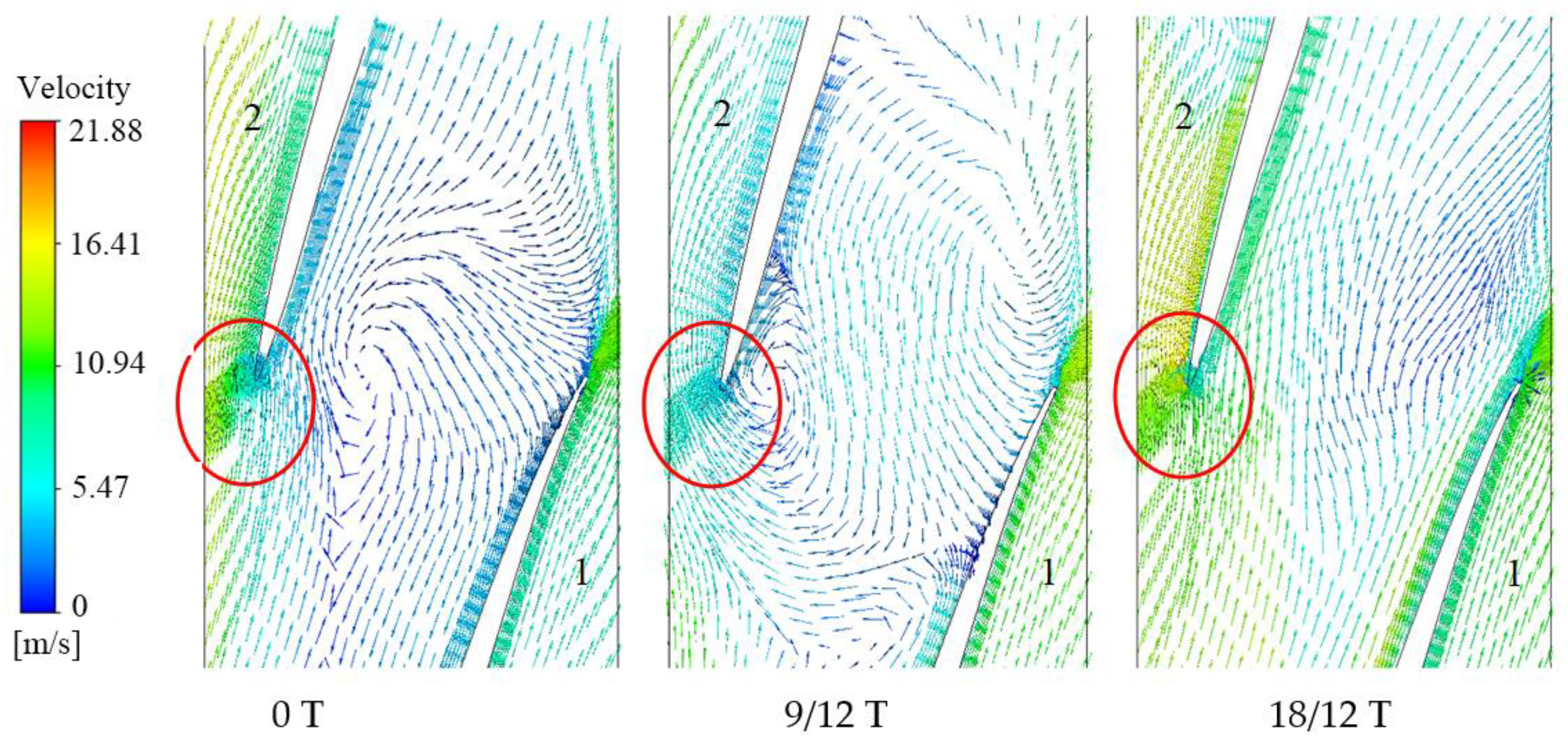
Because the stall core propagates from the leading edge of the blade to the next channel, it has a certain impact on the inlet flow of the next channel. To further analyze the influence of stall core on blade inlet flow field in the process of propagation, the velocity vector of impeller at the 95% blade height spanwise plane under near stall conditions is obtained, as shown in Figure 10. It can be seen from the figure that at 0 T, the inlet stream-line at the leading edge of blade 2 is less affected by the stall core in the passage of blade 1, and the direction of the velocity vector at the leading edge is basically the same as that of the inlet flow of blade 2. As the impeller rotates and the stall core of blade 1 comes closer and closer to the leading edge of blade 2, it can be found that the inlet streamline at the leading edge of blade 2 is more and more affected. Affected by the stall core propagation, the angle between the velocity vector and the suction surface at the leading edge of blade 2 becomes larger and larger, and the squeezing effect on the inlet flow field of blade 2 becomes larger and larger. As the stall core in the flow passage of blade 1 propagates to the flow passage of blade 2, the influence on the inlet flow line at the leading edge of blade 2 begins to weaken because the flow passage of blade 1 gradually exits the stall state. At 18/12 T, the inlet flow line at the leading edge of blade 2 is basically not affected.
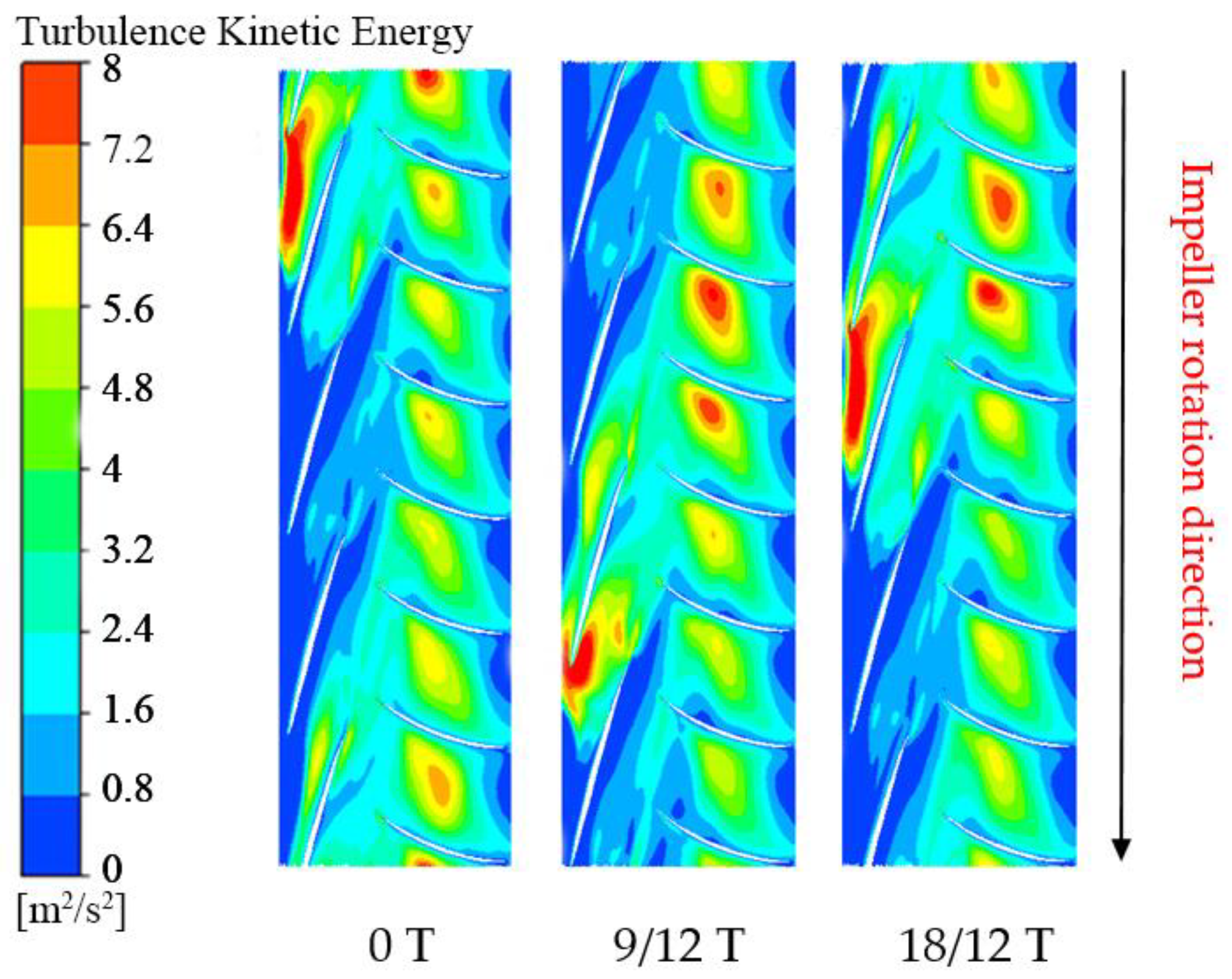
Figure 11 shows the turbulent kinetic energy cloud of impeller and guide vane on the wingspan plane of 95% blade height. It can be seen from the figure that when blade 1 channel stalls, the turbulent kinetic energy of blade 1 channel is much larger than the other three channels, indicating that the energy loss of blade 1 channel is large. At the same time, due to the stall in the passage of blade 1, the turbulent kinetic energy in the guide vane passage is also affected when the fluid flowing from the passage of blade 1 enters the guide vane. It can be found that about three guide vane passages are affected to different degrees, the turbulent kinetic energy in these three guide vane passages is larger than that in other guide vane passages, and the energy loss of the fluid in the guide vane is also larger. With the rotation of the impeller, the stall core gradually propagates from the passage of blade 1 to the passage of blade 2, so the turbulent kinetic energy of the passage of blade 2 increases gradually, while the turbulent kinetic energy of the passage of blade 1 decreases gradually. In this process, about three guide vane channels were affected, but the affected guide vane channels changed due to the rotation of the impeller.
In order to further study the influence of flange clearance on stall propagation, the velocity streamline of the impeller outlet section at different times under near stall condition with δ = 0.5 mm is obtained, as shown in Figure 12. Because of the difference in the flange clearance, the stall channel may be different at the same time, so the stall in the channel of blade 1 is still taken as the starting time. It can be seen from the figure that when δ = 0.5 mm, the stall core changes from one to two, and the two stall cores are in the adjacent channel. In addition, the flow line distortion at the outlet of non-stall flow passage is larger than that at δ = 0.2 mm. With the rotation of the impeller, the stall nuclei in the flow passage of blade 1 and blade 2 start to propagate along the clockwise direction at the same time. Finally, when the stall core is formed in the passage of blade 3, the stall core in the passage of blade 1 disappears, while the stall core still exists in the passage of blade 2. Thus, a stall core propagation is completed, and the propagation period is still about 18/12 T.
Figure 13 shows the pressure distribution of impeller outlet section at different times when δ = 0.5 mm under the same working conditions. It can be seen from the figure that the low-pressure area in the two passages is larger than that in the other two passages due to stall in both passages. However, the pressure distribution in the passage of blade 1 and blade 2 is not the same. The low-pressure area in the passage of blade 1 is slightly larger, which indicates that the stall state of the two passages is still different. With the rotation of the impeller, the low-pressure areas in the two channels move towards the leading edge of the adjacent blades, but the variation of the low-pressure areas in the two channels with time is different. This is because the passage of blade 2 propagates to the passage of blade 3, and the passage of blade 1 also propagates to the passage of blade 2, so the change of the low-pressure region in the passage of blade 2 is not obvious. After the stall core completes a propagation cycle, the low-pressure region in the passage of blade 2 increases.
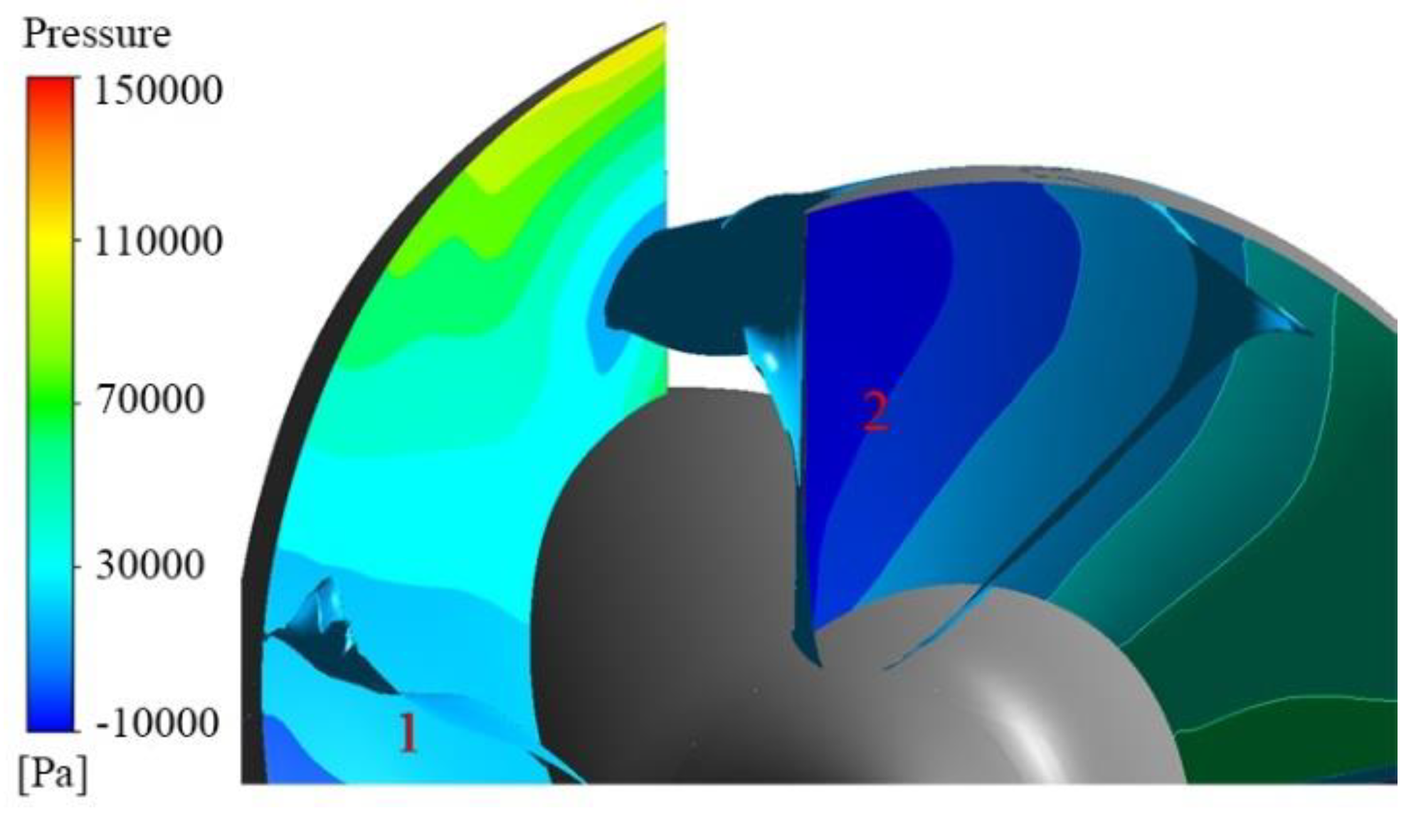
Because of the change from one to two stall nuclei, the propagation process of stall nuclei also changed. Figure 14 shows the pressure contour in the impeller passage at 8/12 T. It can be seen from the figure that although the stall core in the flow passage of blade 1 and blade 2 still propagates from the leading edge of the adjacent blade to the next flow passage, their states are different. When the passage of blade 1 propagates to the passage of blade 2, the stall occurs in the passage of blade 2, so the propagation process is affected to some extent. In the process of the blade 2 passage propagating to the blade 3 passage, although there is no stall in the blade 3 passage, the blade 1 passage is also propagating to the blade 2 passage, so the propagation process of the blade 2 passage will be different. Therefore, when stall occurs in adjacent channels, they will interfere with each other in the propagation process of stall nuclei.
Figure 15 shows the velocity streamline of impeller outlet section at different times when δ = 0.8 mm under near stall conditions. It can be seen from the figure that stall still occurs in the two adjacent channels, and they start to propagate along the clockwise direction at the same time, but the distortion of the streamline at the outlet of the non-stall channel is larger than that at δ = 0.5 mm. In addition, when δ = 0.8 mm, the propagation period of the stall core is about 16/12 T and the propagation period decreases, but the overall trend of the stall core propagation is similar to that when δ = 0.5 mm. It can be found that when the flange clearance increases from 0.2 mm to 0.5 mm, the influence on the internal flow field of the mixed-flow pump is greater than that from 0.5 mm to 0.8 mm. Therefore, compared with the rotating stall characteristics at δ = 0.5 mm, the number of stall nuclei does not change at δ = 0.8 mm, but the propagation period decreases slightly. Because the pressure distribution of the impeller outlet section at different times has a good corresponding relationship with the velocity streamline, the overall trend of the pressure distribution of the impeller outlet section at different times when δ = 0.8 mm is similar to that when δ = 0.5 mm.
3.2. Evolution of Leakage Flow in Near Stall Condition
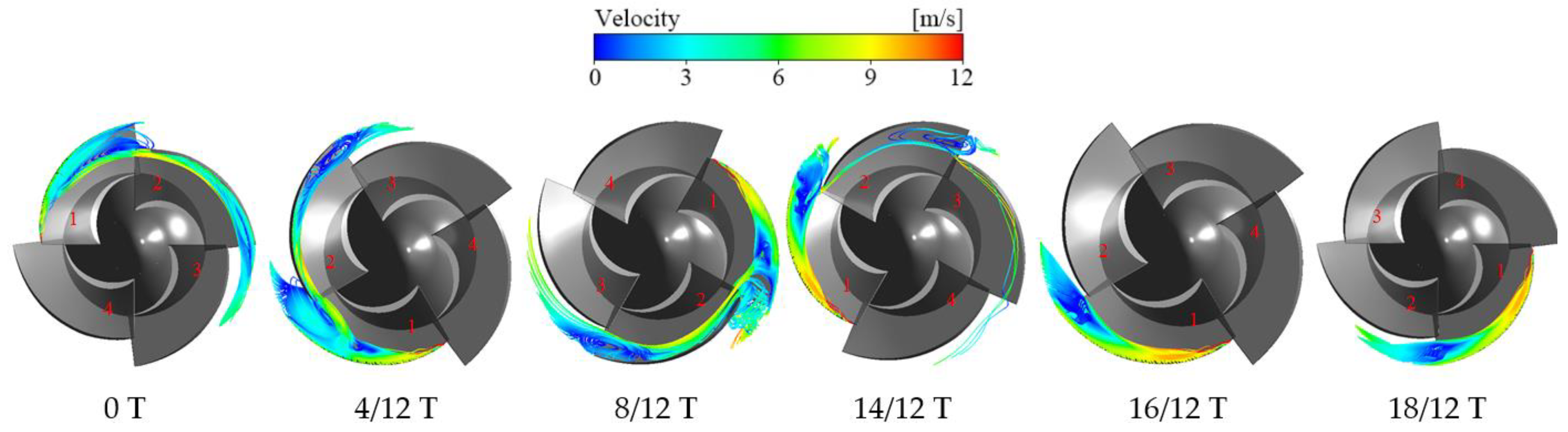
In order to further explore the relationship between flange leakage flow and rotating stall, the evolution law of leakage flow under near stall condition was studied. Figure 16 shows the streamline diagram of leakage flow velocity at different times when δ = 0.2 mm. It can be seen from the figure that from 0 T to 4/12 T, the leakage flow and the mainstream entrainment in the passage of blade 1 gradually form an increasing leakage vortex band, and the leakage flow enters the next passage from the leading edge of blade 2 and gradually forms a vortex at the outlet of blade 2. From 4/12 T to 8/12 T, it can be found that the leakage vortex at the exit of blade 1 is smaller and smaller, while the vortex at the exit of blade 2 is larger and larger. From 8/12 T to 14/12 T, when the leakage vortex at the outlet of blade 1 decreases to a certain extent, the leakage flow from the leading edge of blade 2 into the passage of blade 2 begins to decrease gradually, and the vortex formed at the outlet of blade 2 also begins to decrease gradually. It can be seen that at 14/12 T, the leakage flow at the leading edge of blade 2 is very small. From 14/12 T to 18/12 T, the influence of leakage flow in blade 1 passage on blade 2 passage is smaller and smaller. Finally, the leakage flow in blade 1 passage no longer enters into blade 2 passage from the leading edge of blade 2, reaching a relatively stable state.
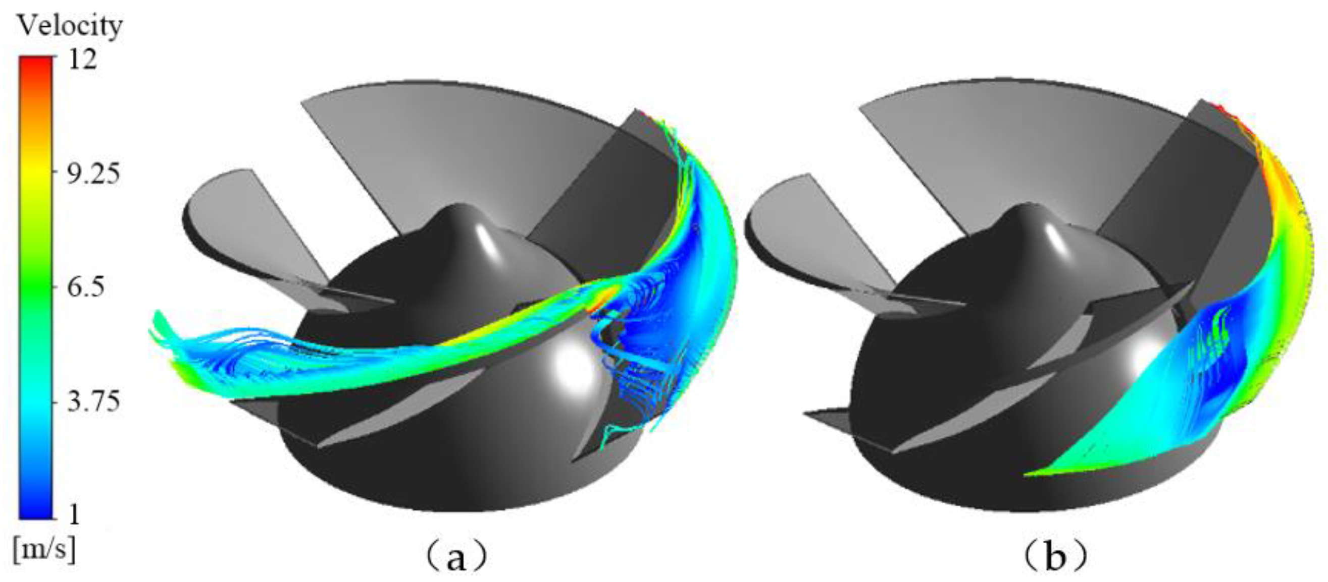
In one propagation cycle of the stall core, the leakage flow in the passage of blade 1 changes from one state to another, corresponding to the passage of blade 1 from stall state to non-stall state. Figure 16 shows the change of leakage flow in the passage of blade 1, and Figure 17a shows the leakage flow in the stall passage. It can be found that the leakage vortex formed by the mixing of leakage flow and main flow is the main factor causing the channel blockage. Due to the blockage effect of the vortex, the leakage flow in the passage of blade 1 diffuses from the leading edge of blade 2 to the passage of blade 2, which has a certain impact on the passage of blade 2, and the current channel blockage has been reduced to a certain extent. When the passage of blade 1 finally exits the stall state, it can be found that the size of the leakage vortex is very small in the non-stall state, and the leakage flow will not affect the next passage, as shown in Figure 17b. In addition, the trajectory of the leakage vortex is directed along the edge of the blade and the overall structure is close to the impeller wall, which greatly reduces the blockage in the flow channel. According to the formation mechanism and circumferential propagation characteristics of the stall core, as well as the variation law of leakage flow and leakage vortex in a stall cycle, leakage flow can be regarded as a form of stall. According to the shape and trajectory of leakage flow in a channel, whether stall occurs in the channel can be judged.
When δ = 0.5 mm and δ = 0.8 mm, it can be seen from the above analysis that stall occurs in the two adjacent channels and the overall propagation trend of stall core is similar; only the propagation period decreases when δ = 0.8 mm. Therefore, this paper only takes δ = 0.5 mm as an example to analyze the variation law of leakage flow. The flow passage of blade 1 still changes from stall state to non-stall state; although the process is different, the overall variation law of leakage flow is like that of δ = 0.2 mm, so it will not be repeated here. However, the passage of blade 2 is always in the stall state, so the leakage flow state in the passage of blade 2 at different times is studied, as shown in Figure 18. It can be seen from the figure that with the rotation of the impeller, the leakage vortex at the outlet of blade 2 does not change much, but the vortex at the outlet of blade 3 increases gradually. Finally, when the passage of blade 1 exits the stall state, the state of leakage flow in the passage of blade 2 does not change much compared with that at 0 T, but the leakage vortex is enhanced, so the influence on the passage of blade 3 is also increased, which is consistent with the change law of stall core in the passage of blade 2.
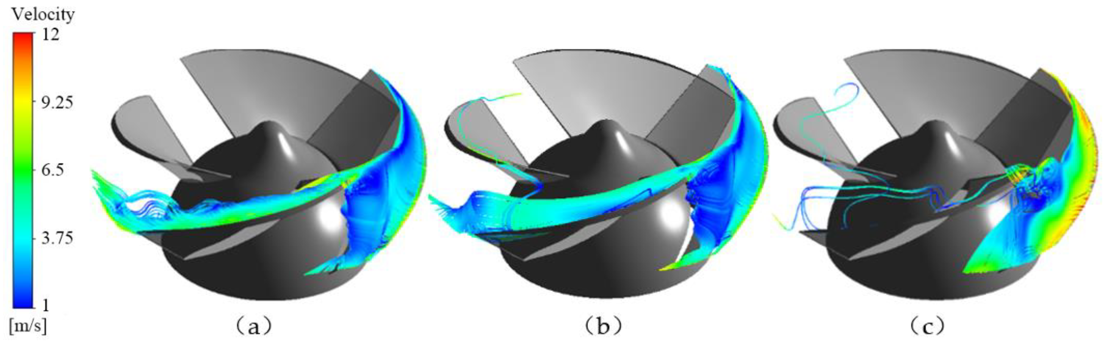
After a stall cycle, the passage of blade 2 also exits the stall state. Figure 19 shows the change of leakage flow form of blade 2 passage from stall state to non-stall state. Figure 19a,b shows the stall state in the passage of blade 2. After a stall cycle, the shape and trajectory of leakage flow in the passage of blade 2 do not change greatly, and the blockage state in the passage is not relieved. After another stall propagation cycle, it can be found that the structure of the leakage vortex in the flow passage has changed to a certain extent, and the blockage state in the flow passage has been greatly reduced, and the flow passage of the corresponding blade 2 has exited the stall state, as shown in Figure 19c. However, differently from δ = 0.2 mm, there is still leakage flow from the leading edge of the adjacent blade into the next channel, which has a certain impact on the next channel, but the impact is small.
3.3. Pressure Fluctuation Characteristics under Near Stall Condition
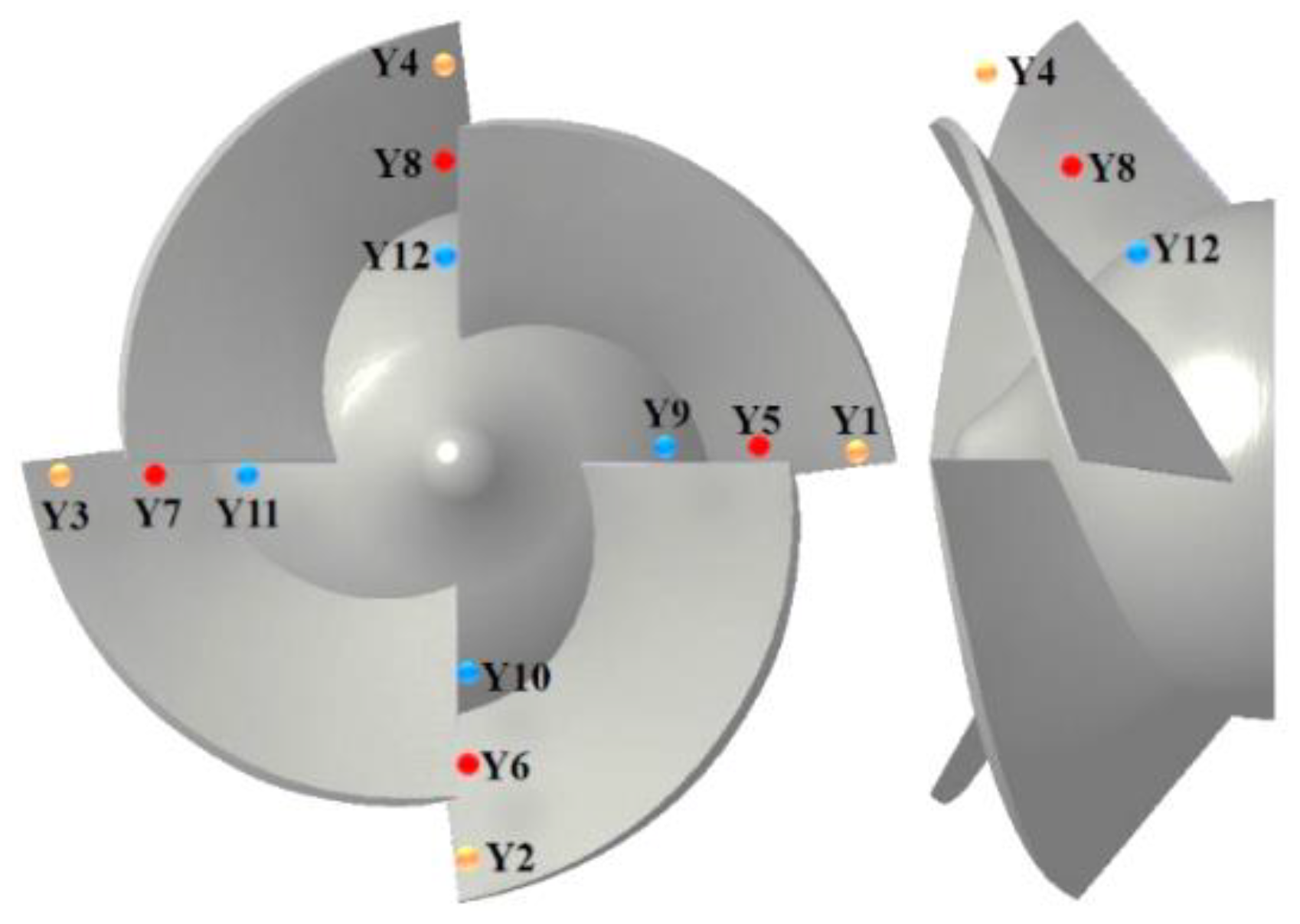
In the near stall condition, the vortex will gradually form at the outlet of the impeller passage, and its blocking effect is obvious. With the rotation of the impeller, the vortex will develop and propagate in the opposite direction of the rotation direction of the impeller. In order to study the propagation characteristics of the stall core, monitoring points are set at the outlet of four flow channels of the impeller, and the monitoring points in each flow channel are arranged from the hub to the rim, as shown in Figure 20. In order to better analyze the pressure fluctuation at each monitoring point, the pressure coefficient Cp is used to deal with the transient pressure dimensionless, which is used to express the intensity of pressure fluctuation.
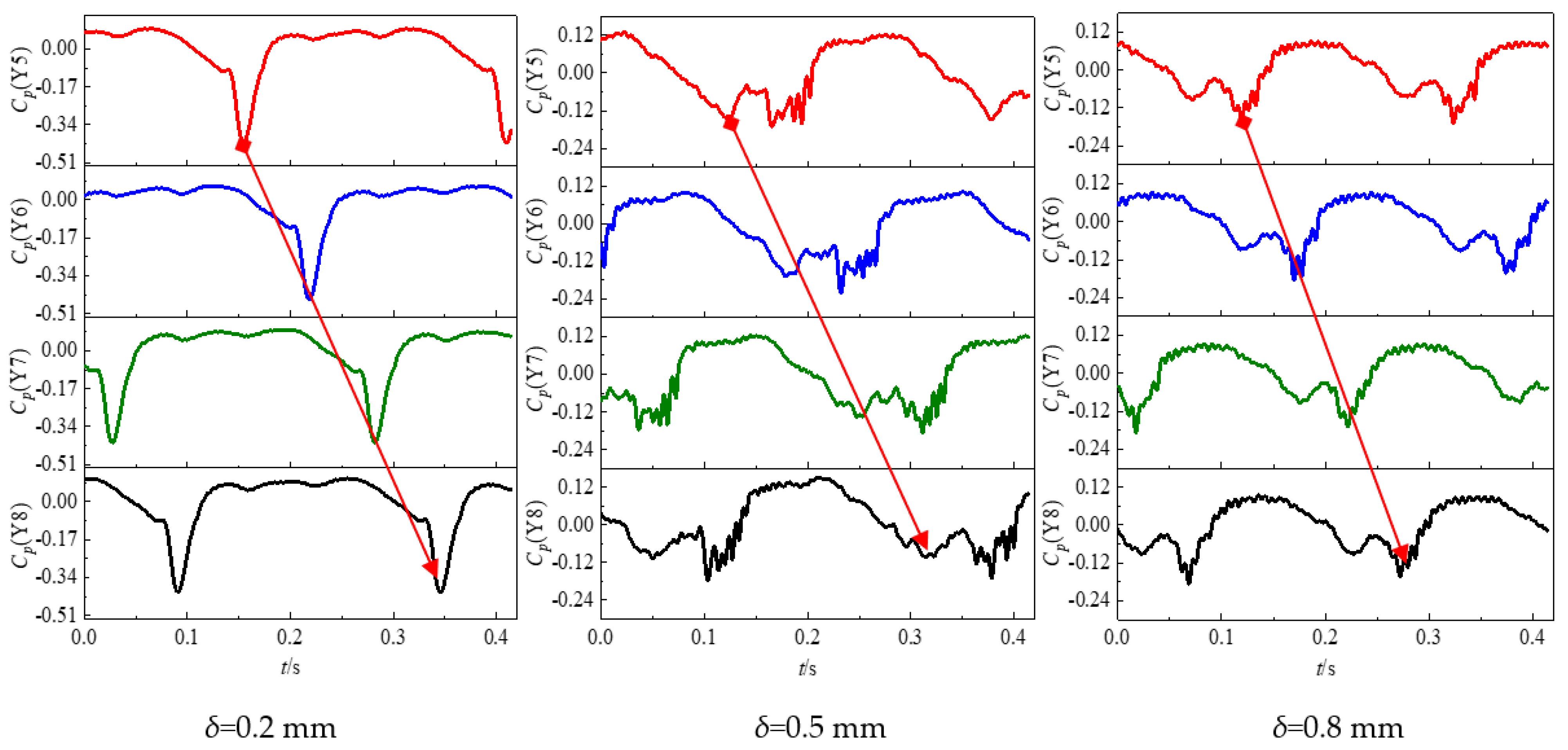
Figure 21 shows the time domain diagram of the pressure fluctuation at the monitoring points Y5, Y6, Y7 and Y8 at the outlet of four flow channels of the impeller under near stall condition. According to the rated speed of the impeller, one rotation cycle of the impeller is T = 0.041397 s, and the total time of abscissa in the figure is t = 0.41397 s, which means that the impeller rotates for 10 cycles. It can be seen from the figure that the pressure fluctuation curves of four monitoring points along the circumferential direction under three different flange clearances show periodic changes under near stall conditions, but the peaks and troughs representing the impeller rotation are not obvious. Under the same flange clearance, the pressure fluctuation curve is similar in different channels, but there is a large phase difference between the adjacent monitoring points, which is caused by the continuous propagation of stall core in the channel. With the rotation of the impeller, there will be a strong pressure drop at the monitoring points in the impeller, which is the main periodic characteristic of the pressure fluctuation curve near stall. It can also be found from the above study that the stall channel has a large pressure gradient, and the propagation of the stall core is accompanied by the propagation of the low-pressure region. When δ = 0.2 mm, the phase difference between adjacent monitoring points is about 18/12 T, which is consistent with one propagation period of stall core. The period of the pressure fluctuation curve at the same monitoring point is about 6 T, which means that the stall core returns to the current channel after four propagation cycles, and there is only one trough in one cycle of the pressure fluctuation curve. When δ = 0.5 mm or δ = 0.8 mm, it can be found that there are two troughs in one cycle of the pressure fluctuation curve. The reason is that the number of stall nuclei changes from one to two, and the propagation of stall nuclei in two adjacent channels is slightly more complicated than that of a single stall nucleus, so the pressure fluctuation curve is slightly more complicated than that of δ = 0.2 mm. In the adjacent channel, the second pressure drop in the current channel corresponds to the first pressure drop in the next channel. After the exit pressure drop of the current channel, the second pressure drop occurs in the next channel, and the first pressure drop occurs in the channel after the next. According to the above research, this process corresponds to the stall vortex propagation process that the current channel exits the stall state, and the next channel continues to be in the stall state, while the channel after next enters the stall state. Because the two stall nuclei will interfere with each other in the process of propagation, the pressure fluctuation curve will fluctuate slightly when it forms two troughs. At the same time, when δ = 0.5 mm, the phase difference between adjacent monitoring points is still about 18/12 T, while when δ = 0.8 mm, the phase difference between adjacent monitoring points is about 16/12 T, which is consistent with the above analysis.
Figure 22 shows the time domain diagram of pressure fluctuation from the hub to the monitoring point of the rim in a single channel with different rim clearances under near stall condition. It can be seen from the figure that the pressure fluctuation amplitude of the monitoring point Y8 located in the middle of the impeller outlet is larger, while the pressure fluctuation amplitude of the monitoring point Y4 located in the hub and flange of the impeller outlet is smaller and the difference is not big, but the pressure fluctuation frequency of the monitoring point Y4 located in the flange is higher. The reason is that near stall condition, the vortex located at the impeller outlet moves along the suction surface of the blade and near the hub, and the main part of the vortex is in the middle of the impeller outlet, which has the greatest impact on the flow. At the same time, when δ > 0.2 mm, the lowest value of pressure fluctuation curve increases. This is because when δ > 0.2 mm, the two stall nuclei in the adjacent channel interfere with each other in the process of propagation.
To analyze the frequency-domain characteristics of pressure fluctuation, the fast Fourier transform (FFT) algorithm is used to transform the time domain information into the frequency domain. Figure 23 shows the frequency domain diagram of pressure fluctuation at three monitoring points from hub to flange in a single flow passage of the impeller under near stall condition with different flange clearance, in which abscissa f * is the multiple of impeller rotation frequency. It can be seen from the figure that the main frequency of the frequency domain curve of pressure fluctuation at the three monitoring points is not the impeller rotation frequency or blade frequency, but 0.2 times of the rotation frequency, and the amplitude of the main frequency is high, which is the stall frequency. At the same time, the main frequency amplitude of the monitoring point Y8 located in the middle of the impeller outlet is the largest, while the main frequency amplitude of the monitoring points Y12 and Y4 located in the hub and flange is smaller and the difference is not significant. This is because the main part of the stall core is located in the middle of the impeller outlet, so it has the greatest impact on the pressure fluctuation of the fluid there and has less impact on the pressure fluctuation of the fluid at the hub and flange.
In the near stall condition, the stall state in the impeller is different due to the different flange clearance, which will have a certain impact on the frequency-domain curve of the pressure fluctuation at the three monitoring points. Because the main part of the stall core is located in the middle of the impeller outlet, the impact on the frequency-domain curve of the pressure fluctuation at the monitoring point is the most obvious. When δ = 0.2 mm, the main frequency amplitude of Y8 frequency domain curve at impeller outlet monitoring point is larger, and the main frequency attenuation is slower. When δ = 0.5 mm, due to the existence of two stall cores, compared with the single channel propagation mode, the pressure drop amplitude is weaker, so the main frequency amplitude is reduced, and the main frequency attenuation is faster. In addition, the frequency components on the frequency-domain curve are increased when δ = 0.2 mm, which is due to the interference between the two stall nuclei. When δ = 0.8 mm, there are still two stall cores, so the overall trend of frequency-domain curve is similar to that when δ = 0.5 mm, but the amplitude of the main frequency increases.
4. Conclusions
- (1)
- In the near stall condition, the vortices at the impeller outlet develop and disappear in turn in the impeller passage, and propagate along the opposite direction of blade rotation. According to the formation mechanism of rotating stall, the vortex is the stall core. When there is a stall core in the channel, the flow field has a large pressure gradient and the energy loss in the channel is large. In the process of propagation, the stall core propagates from the leading edge of the adjacent blade to the next channel, so the inlet flow field of the adjacent blade channel will be squeezed, resulting in a certain energy loss. At the same time, the flow capacity in the adjacent channel gradually weakens, which aggravates the channel blockage and gradually enters the stall state.
- (2)
- When δ = 0.2 mm, there is only one stall core in the impeller passage, and the propagation period is about 18/12 T. When δ = 0.5 mm, the stall core changes from one to two and is in two adjacent channels, but the propagation period is still about 18/12 T. When δ = 0.8 mm, there are still stall nuclei in the two adjacent channels, but the propagation period is reduced to about 16/12 T. When stall occurs in two adjacent channels, the pressure distribution in the two channels is not the same, which indicates that the stall state in the two channels is not the same. Because the stall nuclei propagate in two adjacent channels and in the opposite direction of blade rotation simultaneously, the propagation process of stall nuclei will interfere with each other, which is different from the propagation process in which there is only a single stall nucleus in the channel.
- (3)
- The variation law of leakage flow is consistent with the propagation law of the stall core. When the impeller passage changes from stall state to non-stall state, the leakage flow in the passage changes from one state to another, and stall has a great influence on the leakage flow. Therefore, the leakage flow can be regarded as a form of stall. The analysis of the shape and trajectory of the leakage flow in the channel can provide a basis for judging whether the stall occurs in the channel.
- (4)
- In the near stall condition, the time domain curves of pressure fluctuation at each monitoring point show periodic changes, but the characteristics of the peaks and troughs representing the impeller rotation are fuzzy. There is a large phase difference between adjacent monitoring points and a strong pressure drop on the time domain curve, which is the main periodic characteristic of the pressure fluctuation curve near stall. The phase difference between the adjacent monitoring points is consistent with the propagation period of the stall core under different wheel gaps. With the increase in the size of the gap, the propagation mechanism of the stall nuclei tends to become more complicated due to the increase in the number of stall nuclei, so that two wave troughs appear in one cycle of the time domain curve of the pressure fluctuation. In addition, since the main part of the vortex is in the middle of the impeller outlet, the pressure fluctuation of Y8 is the largest.
- (5)
- In the near stall condition, the amplitudes of pressure fluctuation frequency-domain curves at three monitoring points in the same channel are quite different, but the main frequency is 0.2 times of the impeller rotation frequency, i.e., stall frequency. In addition, the main frequency amplitude of the frequency-domain curve of the middle monitoring point Y8 is the largest. When the number of stall cores is the same, the larger the gap, the larger the main frequency amplitude.
Author Contributions
Conceptualization, W.L.; methodology, W.L.; software, D.L. and L.J.; validation, D.L., S.L. and L.J.; formal analysis, D.L., S.L. and L.J.; investigation, S.L. and L.J.; resources, W.L.; data curation, D.L., L.J. and Y.Y.; writing—original draft preparation, D.L.; writing—review and editing, W.L. and D.L.; visualization, Y.Y.; supervision, W.L.; project administration, W.L.; funding acquisition, W.L. All authors have read and agreed to the published version of the manuscript.
Funding
This research was funded by [the Key International Cooperative research of National Natural Science Foundation of China] grant number [No.52120105010], [the National Natural Science Foundation of China] grant number [No.52179085], [the National Key R&D Program Project] grant number [No.2020YFC1512405], [the Fifth 333 High Level Talented Person Cultivating Project of Jiangsu Province], [Funded projects of Blue Project in Jiangsu Colleges and Universities], [Belt and Road Innovation Cooperation Project of Jiangsu Province] grant number [No.BZ2020068], [Independent Innovation Fund Project of Agricultural Science and Technology in Jiangsu Province] grant number [No.CX(20)2037].
Institutional Review Board Statement
Not applicable.
Informed Consent Statement
Not applicable.
Data Availability Statement
Not applicable.
Conflicts of Interest
The authors declare no conflict of interest.
References
- Ji, L.; Li, W.; Shi, W.; Tian, F.; Agarwal, R. Diagnosis of internal energy characteristics of mixed-flow pump within stall region based on entropy production analysis model. Int. Commun. Heat Mass Transf. 2020, 117, 104784. [Google Scholar] [CrossRef]
- Ye, W.; Ikuta, A.; Chen, Y.; Miyagawa, K.; Luo, X. Numerical simulation on role of the rotating stall on the hump characteristic in a mixed flow pump using modified partially averaged Navier-Stokes model. Renew. Energy 2020, 166, 91–107. [Google Scholar] [CrossRef]
- Ji, L.; Li, W.; Shi, W.; Chang, H.; Yang, Z. Energy characteristics of mixed-flow pump under different tip clearances based on entropy production analysis. Energy 2020, 199, 117447. [Google Scholar] [CrossRef]
- Li, W.; Li, E.; Ji, L.; Zhou, L.; Shi, W.; Zhu, Y. Mechanism and propagation characteristics of rotating stall in a mixed-flow pump. Renew. Energy 2020, 153, 74–92. [Google Scholar] [CrossRef]
- Li, W.; Ji, L.; Li, E.; Shi, W.; Agarwal, R.; Zhou, L. Numerical investigation of energy loss mechanism of mixed-flow pump under stall condition. Renew. Energy 2020, 2021, 740–760. [Google Scholar] [CrossRef]
- Li, W.; Ping, Y.; Shi, W.; Ji, L.; Li, E.; Ma, L. Research progress in rotating stall in mixed-flow pumps with guide vane. J. Drain. Irrig. Mach. Eng. 2019, 37, 737–745. [Google Scholar]
- Ye, W.; Ikuta, A.; Chen, Y.; Miyagawa, K.; Luo, X. Investigation on the effect of forward skew angle blade on the hump characteristic in a mixed flow pump using modified partially averaged Navier-Stokes model. Renew. Energy 2021, 170, 118–132. [Google Scholar] [CrossRef]
- Hu, B.; Zhang, S.; Sun, Z. Influence of relative position of diffuser leading edge on pressure pulsation in mixed-flow pump. J. Drain. Irrig. Mach. Eng. 2021, 39, 16–22. [Google Scholar]
- Yue, H.; Lei, T. Symmetrical and unsymmetrical tip clearances on cavitation performance and radial force of a mixed-flow pump as turbine at pump mode. Renew. Energy 2018, 127, 368–376. [Google Scholar]
- Ji, L.; Li, W.; Shi, W. Influence of tip leakage flow and inlet distortion flow on a mixed-flow pump with different tip clearances within the stall condition. Proc. Inst. Mech. Eng. Part A J. Power Energy 2020, 234, 433–453. [Google Scholar] [CrossRef]
- Li, Y.; He, H.; Fan, Z.; Li, J. Effect of blade tip clearance on cavitating flow in mixed-flow pump. J. Drain. Irrig. Mach. Eng. 2020, 38, 224–229. [Google Scholar]
- Desheng, Z.; Xi, S.; Yaguang, D.; Chaochao, W.; An, L.; Weidong, S.H.I. Numerical simulation of different blade tip clearances on internal flow characteristics in mixed-flow pump. J. Drain. Irrig. Mach. Eng. 2020, 38, 757–763. [Google Scholar]
- Ping, Y.; Shi, W.; Li, W.; Ji, L.; Li, E.; Ma, L. Rotating stall characteristics of mixed-flow pump under different flange clearances. J. Cent. South Univ. (Sci. Technol.) 2019, 50, 2109–2117. [Google Scholar]
- Inoue, Y.; Nagahara, T.; Sato, T. Application of PIV for the flow field measurement in a mixed-flow pump. In Proceedings of the 26th IAHR Symposium on Hydraulic Machinery and Systems, Beijing, China, 19–23 August 2012; Volume 15, p. 022011. [Google Scholar]
- Sinha, M.; Pinarbashi, A.; Katz, J. The flow structure during onset and developed states of rotating stall within a vaned diffuser of a centrifugal pump. ASME J. Fluids Eng. 2001, 123, 490–499. [Google Scholar] [CrossRef] [Green Version]
- Goltz, I.; Kosyna, G.; Stark, U.; Saathoff, H.; Bross, S. Stall inception phenomena in a single-stage axial flow Pump. Proc. Inst. Mech. Eng. Part A J. Power Energy 2003, 217, 471–479. [Google Scholar] [CrossRef]
- Ma, Y.; Xi, G.; Wu, G. Numerical simulation of tip clearance flow characteristics of small centrifugal impeller. In Proceedings of the Chinese Society of Engineering Thermophysics, Wuhan, Beijing, 2011. [Google Scholar]
- Li, X.; Yuan, S.; Pan, Z.; Li, Y.; Liu, W. Dynamic characteristics of rotating stall in mixed-flow pump. J. Appl. Math. 2013, 2013, 104629. [Google Scholar] [CrossRef]
- Kim, D.J.; Min, Y.U.; Kim, J.Y.; Chung, K.N. A study of tip clearance effect for a mixed-flow pump on performance. In Proceedings of the ASME 2013 Fluids Engineering Division Summer Meeting, Incline Villag, NV, USA, 7–11 July 2013; Volume 55553, p. V01BT10A022. [Google Scholar]
- Li, Y.; Hu, P.; Li, R.; Li, P.; Bi, Z. Numericalanalysis for effects of different blade tip clearance on performance in mixed-flow pump. Trans. Chin. Soc. Agric. Eng. 2014, 30, 86–93. [Google Scholar]
- Li, W.; Agarwal, R.K.; Zhou, L.; Li, E.; Ji, L. Effect of Tip Clearance on Rotating Stall in a Mixed-Flow Pump. J. Turbomach. 2021, 143, 091013. [Google Scholar] [CrossRef]
- Goto, A. The effect of tip leakage flow on part-load performance of a mixed-flow pump impeller. J. Turbomach. 1992, 114, 383–391. [Google Scholar] [CrossRef]
- Li, B.V.E. Unstable Operation of a mixed-flow pump and the influence of tip clearance. In Proceedings of the ASME-JSME-KSME 2011 Joint Fluids Engineering Conference, Hamamatsu, Japan, 24–29 July 2011; Volume 1. [Google Scholar]
- Miyabe, M.; Furukawa, A.; Maeda, H.; Umeki, I. Rotating stall behavior in a diffuser of mixed-flow pump and its suppression. In Proceedings of the ASME Fluids Engineering Division Summer Meeting Collocated with the Heat Transfer, Jacksonville, FL, USA, 10–14 August 2008. [Google Scholar]
- Zhang, R. Research on the Stall and Cavitation Flow Characteristics and the Performance Improvement of Axial-Flow Pump. Ph.D. Thesis, Shanghai University, Shanghai, China, 2014. [Google Scholar]
- Jin, S.; Wang, Y.; Chang, S.; Su, Y. Pressure fluctuation of interior flow in mixed-flow pump. Trans. Chin. Soc. Agric. Mach. 2013, 44, 64–68. [Google Scholar]
- Yamade, Y.; Kato, C.; Shimizu, H.; Nagahara, T. Large eddy simulation of internal flow of a mixed-flow pump. In Proceedings of the Fluids Engineering Division Summer Meeting, Vail, CO, USA, 2–6 August 2009; pp. 407–416. [Google Scholar]
- Miyabe, M.; Maeda, H.; Umeki, I.; Jittani, Y. Unstable head-flow characteristic generation mechanism of a low specific speed mixed-flow pump. J. Therm. Sci. 2006, 15, 115–120. [Google Scholar] [CrossRef]
- Miyabe, M.; Furukawa, A.; Maeda, H.; Umeki, I.; Jittani, Y. A behavior of the diffuser rotating stall in a low specific speed mixed-flow pump. Int. J. Fluid Mach. Syst. 2009, 35, 113–121. [Google Scholar] [CrossRef] [Green Version]
- Zhang, D.S.; Wang, C.C.; Dong, Y.G.; Shi, L.; Jin, Y.X. Tests for Inner Pressure Fluctuation Features in an Oblique Flow Pump with High Ratio Rotating Speed. J. Vib. Shock. 2019, 38, 27–34. [Google Scholar]
- Yibin, L.; Rennian, L.; Xiuyong, W.; Wei, H.; Qiang, G. Numerical analysis of pressure fluctuation in low specific spreed mixed-flow pump. J. Drain. Irrig. Mach. Eng. 2013, 31, 205–209. [Google Scholar]
- Yibin, L.; Rennian, L.; Xiuyong, W.; Weiguo, Z.; Penghui, L. Numerical simulation of unstable characteristics in head curve of mixed-flow pump. J. Drain. Irrig. Mach. Eng. 2013, 31, 384–389. [Google Scholar]
Figure 1.
Mixed-flow pump model. (a) Impeller and guide vane, (b) Calculation domain water body.

Figure 2.
General and refined mesh of computational domains. (a) Impeller grid, (b) Guide vane grid, (c) Mesh refinement in rim region.
Figure 2.
General and refined mesh of computational domains. (a) Impeller grid, (b) Guide vane grid, (c) Mesh refinement in rim region.

Figure 3.
Experimental setup.

Figure 4.
Comparison of external characteristics between CFD and experiment.

Figure 5.
Comparison of CFD and PIV test results.

Figure 6.
Section position of impeller outlet.

Figure 7.
Velocity streamline diagram of impeller outlet section at different time (δ = 0.2 mm).

Figure 8.
Pressure nephogram of impeller outlet section at different time (δ = 0.2 mm).

Figure 9.
Pressure iso-surface of impeller passage at 8/12 T (δ = 0.2 mm).

Figure 10.
Velocity vector of impeller on the plane at 95% of span (δ = 0.2 mm).

Figure 11.
Turbulent kinetic energy of impeller and guide vane on the plane at 95% of span (δ = 0.2 mm).
Figure 11.
Turbulent kinetic energy of impeller and guide vane on the plane at 95% of span (δ = 0.2 mm).

Figure 12.
Velocity streamline diagram of impeller outlet section at different time (δ = 0.5 mm).

Figure 13.
Pressure nephogram of impeller outlet section at different times (δ = 0.5 mm).

Figure 14.
Pressure iso-surface of impeller passage at 8/12 T (δ = 0.5 mm).

Figure 15.
Velocity streamline diagram of impeller outlet section at different time (δ = 0.8 mm).

Figure 16.
Velocity streamline diagram of leakage flow at different time (δ = 0.2 mm).

Figure 17.
Form change of leakage flow (δ = 0.2 mm).

Figure 18.
Velocity streamline diagram of leakage flow at different time (δ = 0.5 mm).

Figure 19.
Form change of leakage flow (δ = 0.5 mm).

Figure 20.
Position of impeller outlet monitoring points.

Figure 21.
Time domain diagram of pressure fluctuation at impeller outlet monitoring point (Y5, Y6, Y7, Y8).
Figure 21.
Time domain diagram of pressure fluctuation at impeller outlet monitoring point (Y5, Y6, Y7, Y8).

Figure 22.
Time domain diagram of pressure fluctuation at impeller outlet monitoring point (Y4, Y8, Y12).
Figure 22.
Time domain diagram of pressure fluctuation at impeller outlet monitoring point (Y4, Y8, Y12).

Figure 23.
Frequency domain diagram of pressure fluctuation at impeller outlet monitoring point (Y4, Y8, Y12).
Figure 23.
Frequency domain diagram of pressure fluctuation at impeller outlet monitoring point (Y4, Y8, Y12).


Table 1.
Parameters of mixed-flow pump.
| Parameter | Value |
|---|---|
| Designed flow rate Qdes (m3/h) | 380 |
| Designed rated head H (m) | 6 |
| Rated speed n (r/min) | 1450 |
| Specific speed ns | 480 |
| Number of impeller blades Z | 4 |
| Number of guide vane blades Zd | 7 |
Table 2.
Calculation of head under different grid numbers.
| Grid Number (million) | Head (m) |
|---|---|
| 1.86 | 5.2935 |
| 3.59 | 5.5895 |
| 4.91 | 5.6106 |
| 5.62 | 5.6131 |
| 7.32 | 5.6066 |
Publisher’s Note: MDPI stays neutral with regard to jurisdictional claims in published maps and institutional affiliations. |
© 2022 by the authors. Licensee MDPI, Basel, Switzerland. This article is an open access article distributed under the terms and conditions of the Creative Commons Attribution (CC BY) license (https://creativecommons.org/licenses/by/4.0/).
Share and Cite
MDPI and ACS Style
Lu, D.; Li, W.; Li, S.; Ji, L.; Yang, Y. Research on the Relationship between Stall Propagation and Flange Leakage of Mixed-Flow Pumps. Water 2022, 14, 1730. https://doi.org/10.3390/w14111730
AMA Style
Lu D, Li W, Li S, Ji L, Yang Y. Research on the Relationship between Stall Propagation and Flange Leakage of Mixed-Flow Pumps. Water. 2022; 14(11):1730. https://doi.org/10.3390/w14111730
Chicago/Turabian StyleLu, Dele, Wei Li, Shuo Li, Leilei Ji, and Yi Yang. 2022. "Research on the Relationship between Stall Propagation and Flange Leakage of Mixed-Flow Pumps" Water 14, no. 11: 1730. https://doi.org/10.3390/w14111730
Note that from the first issue of 2016, this journal uses article numbers instead of page numbers. See further details here.