
Analysis of Flow Channel Structure Parameter and Optimization Study on Tooth Spacing of Drip Irrigation Tape

College of Water Conservancy Engineering, Tianjin Agricultural University, Tianjin 300384, China
*
Author to whom correspondence should be addressed.
Water 2022, 14(11), 1694; https://doi.org/10.3390/w14111694
Submission received: 29 March 2022
/
Revised: 15 May 2022
/
Accepted: 16 May 2022
/
Published: 25 May 2022
(This article belongs to the Special Issue Advances in Sprinkler Irrigation Systems and Water Saving)
Abstract
:The flow channel structure is the main factor affecting the hydraulic performance, anti-clogging and energy dissipation performance of drip irrigation tape. Proper exploring of the performance-related but hard-to-measure structure parameters in the flow channel emitter of drip irrigation tape is imperative. However, the traditional studying methods may lead to large systematic errors and human errors, resulting in inaccurate estimations of the parameters and an unreasonable design. This paper aims to find an effective way to optimize the most significant channel structural parameter through studying 18 kinds of drip irrigation belts commonly used in the agricultural irrigation field. Unigraphics NX and Spaceclaim were applied to measure the eight main structure parameters of the selected drip irrigation tapes. The one critical parameter that affects the emitter hydraulic performance—tooth spacing—was found by Principal Component Analysis (PCA). Therefore, we designed three plans where the tooth spacing decreased by 0.1, 0.2, and 0.29 mm to 1.36, 1.26, and 1.17 mm, respectively, and, finally, formed two types of flow channels. Flow channel 1 with a tooth base is represented by Plan 1 and Plan 2, and flow channel 2 without a tooth base is represented by Plan 3. Then, computational fluid dynamics (CFD) was used to simulate the flow characteristics of the emitters in the three plans. The results demonstrate that flow channel 2 without a tooth base, represented by Plan 3, has a greater kinetic energy and hydraulic performance than flow channel 1. Compared with the control group, the changes in Plan 3 were the most obvious, with the changes in the flow index, flow coefficient, and average flow rate by −14.50%, −5.08%, and 12.50%, respectively. The flow indexes in the three plans are all less than 0.5, while the smallest of Plan 3 is 0.395. Therefore, the hydraulic performance of flow channel 2 represented by Plan 3 is better. The narrowing of the tooth spacing makes the space for vortexing between the serrated teeth smaller. The flow velocity in Plan 3 is generally increased by 3 m/s from 2.3 to 4.1 m/s, becoming more uniform. Due to a high velocity of the water flow and less vortexing, the deposition of suspended solids in the flow channel is avoided to a certain extent, and for the flow channel in Plan 3, the improvement in the hydraulic performance is greater than the reduction in the energy dissipation performance. The ratio of the decrease in the flow index to the increase in the average outflow of the emitter in Plan 3 is 1.16:1. In conclusion, the overall performance of Plan 3 is optimal for all schemes. Flow channel 2 can improve the hydraulic performance and reduce the production costs. Therefore, this study could provide a theoretical induction for inner drip irrigation tape application and production.
1. Introduction
Drip irrigation tape is one of the most rapidly developed and widely used water-saving irrigation equipment materials in the country. As the core component of the drip irrigation system, the drip irrigation emitters’ working performance largely affects the irrigation quality. Moreover, optimizing the flow path structure of emitters and ensuring a good flow state within the flow path is the main way to enhance the emitters’ performance. Therefore, how to improve the channel structural performance of the drip irrigation emitter and improve the irrigation quality are essential issues that need to be solved in the development and promotion of drip irrigation technology. At present, to study and design new advanced drip irrigation emitters, scholars frequently combine the physical experiment method and a numerical simulation based on computational fluid dynamics (CFD) [1,2,3,4].
The emitters of drip irrigation tape are closely related to the hydraulic performance of the channel because of its variable structure [5,6,7,8]. Based on numerical simulation and physical entity experiments, Xing et al. proposed a new kind of channel structure of drip irrigation emitters based on the structures of scalariform perforation plates in plant xylem vessels [9]. Wu et al. optimized the labyrinth path structure by realizing the internal flow visualization inside the drip irrigation emitter [10]. Xu et al. designed four schemes to find a pit drip irrigation emitter (PDIE) in which the energy dissipation coefficient and anti-clogging ability were the optimal ones. The results indicated that, by reducing the flow area at the upper and lower ends of the PDIE and adding the resistance of the torus edge, the optimal designs of Scheme 3 with added two triangles and Scheme 4 with added arcs and triangles had good working performances [11]. However, conventional physical tests are difficult for revealing the internal flow state and water flow movement of the drip irrigation emitter, so there will often be large systematic errors and human errors when measuring some macroindicators such as the pressure flow.
Additionally, concentrating on the structural parameter affecting the working performance of drip irrigation emitters is the direct and valid approach to optimize the flow channel. A study conducted by Li et al. [12] revealed that tooth spacing has a significant influence on the flow index and clogging performance of emitters. Tian et al. [13] investigated the effects of the structural parameters on the hydraulic performances of the bidirectional flow channel of the drip irrigation emitter through choosing nine key factors from the structural parameters and arranging 12 experimental schemes. Wang et al. [14] carried out research on the structure parameters of the emitter, and the result showed that the channel width has a greater influence on the hydraulic performance and anticlogging performance of the emitter than the channel depth, and the order of these parameters affecting the flow index was tooth spacing > channel depth > tooth angle > tooth height. Zhang et al. [15] established and processed the computational domain of the emitters through Ansys icem CFD and fluent software, and the results indicated that the flow index of the channel is positively correlated with the tooth spacing but is negatively correlated with the tooth width and tooth height. Based on the numerical simulation experiment of the emitters by using CFD software, Ma et al. [16] designed a variable curvature labyrinth channel emitter, which revealed the internal flow characteristics and dissipation mechanism of the emitter and provided a theoretical basis for the development of a new emitter.
For research on the performance of the emitter, many of the above-mentioned scholars mostly focus on the optimization of the patch flow channel parameters to improve the overall flow channel performance. While the accuracy of the traditional microscale measuring instruments, such as a Vernier caliper and micrometer, can only be 0.01 mm, it is difficult to accurately measure the parameters, such as the width and depth of the very small flow channel, which makes it easy to cause a systematic error. In addition, there is no traditional measurement precision equipment to meet the measure demands for the sawtooth curvature of the emitter, or the cost of the precise measurement instrument is very high. Using the numerical calculation platform to divide the mesh of the emitter geometry is also a critical step for analyzing the internal structural parameters and flow pattern of the emitter. In the past, some software, such as Gambit, ICEM CFD, or Workbench, was produced by ANSYS (Ansys, Canonsburg, PA, USA) and applied to form meshing patterns of the emitters and then select a FLUENT numerical simulation to obtain the research results [17,18,19,20,21]. However, these kinds of software have poor accuracy when generating 3D images to measure the physical size of a flow channel. This complicated method, without comprehensive consideration in the boundary conditions, is time-consuming and has low credibility [22].
In order to solve the above problems, this paper firstly uses the Easson 3D scanner to obtain high-precision 3D images and then measure the flow channel structural parameters of the inner patch emitter with Unigraphics NX and Spaceclaim modeling software. Furthermore, the geometry of the emitter was modeled and repaired with Spaceclaim, and the outflow boundary conditions were supplemented and improved. The author added an outlet in the outlet section of the water storage tank to simulate drip irrigation, meshed the geometry with fluent meshing, and finally, brought it into the FLUENT solver for a numerical simulation. Therefore, this paper can improve the accuracy of the numerical simulation and the efficiency of research and production, because it greatly saves the time needed with the conventional meshing software to construct the computational domain. More importantly, it is beneficial to provide a theoretical reference for the design of a low-cost emitter with an excellent hydraulic performance and anticlogging and energy dissipation performance.
2. Materials and Methods
2.1. Materials
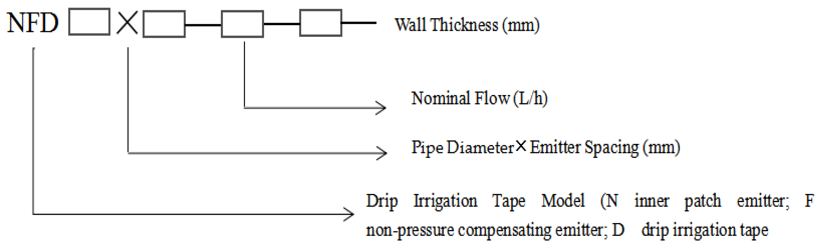
Through investigation, this paper finally selected 18 drip irrigation tapes commonly used in Northern China as the test samples. The drip irrigation tape provided by Tianjin DAYU Water-saving Group Co., Ltd. was made of black rubber material, with a wall thickness of 0.1 to 0.2 mm, an emitter spacing of 100–300 mm, and a pipe diameter of 12–20 mm. Table 1 shows the product parameters of the inner patch channel on the emitter of the drip irrigation tape, and Figure 1 is the instructions of the drip irrigation tape number.
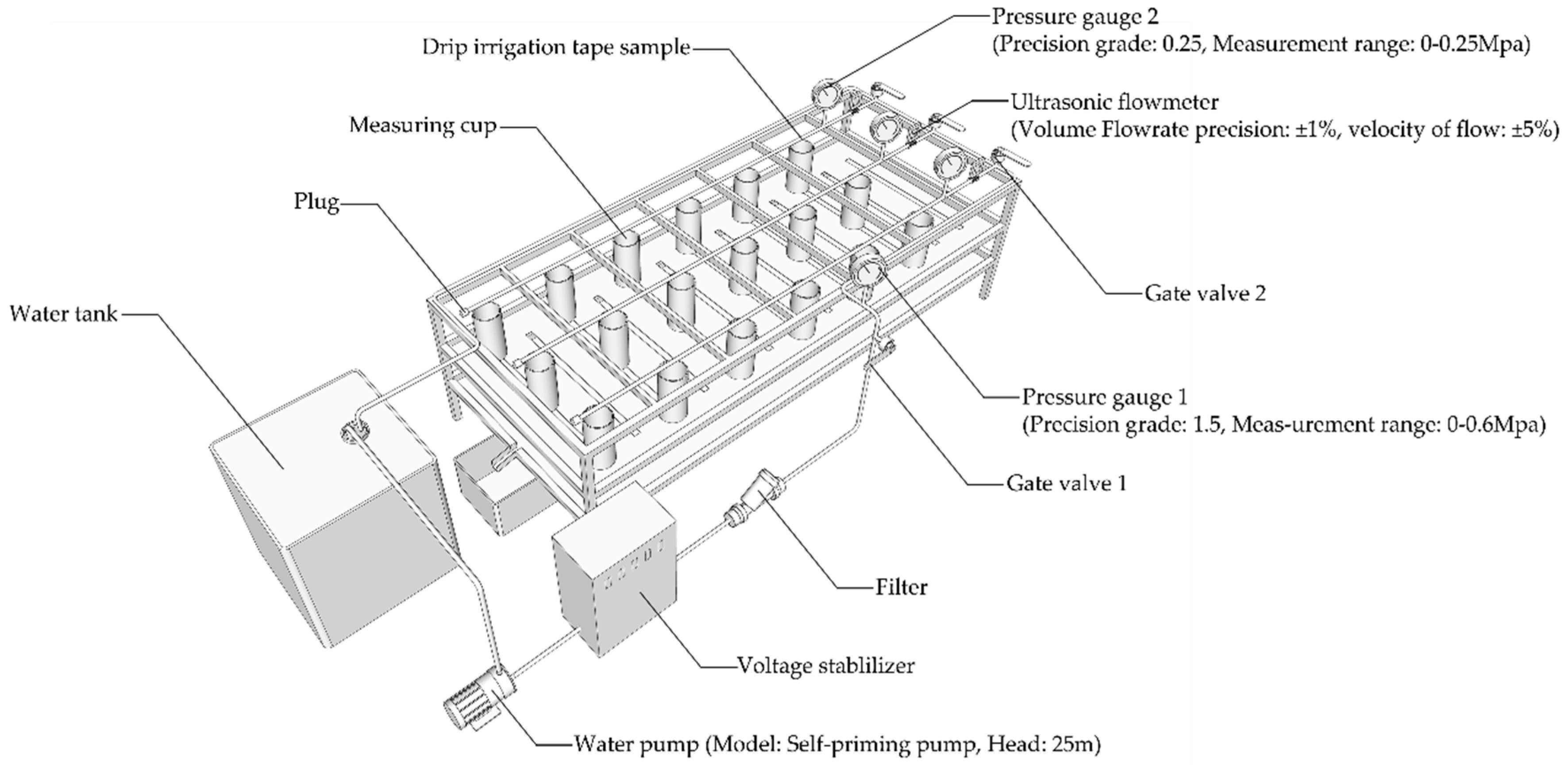
With the help of Easson 3D, an image scanner of Shanghai Huawei, a 3D geometric image was formed of the drip irrigation patch emitter based on the structured light 3D scanning principle. The related technical parameters of Easson 3D were as follows: resolution (0.025 mm), maximum scan rate (1,300,000 measurements/sec), and highest precision (0.02 mm). Unigraphics NX and Spaceclaim were the main 3D modeling software to accurately measure the structural parameters of the required patch flow channel in this paper. As shown in Figure 2, the hydraulic performance experiment was carried out using a test setup that consisted of a water pump, voltage stabilizer, filters, pressure gauges, electromagnetic flowmeters, and so on [23,24].
2.2. Methods
The experiment of measuring the flow channel structure parameters firstly applied Easson 3D to test and scan the drip irrigation patch. Then, it imported the scan results into Unigraphics NX and used that to obtain the actual size of each structural parameter. Finally, Spaceclaim was used to remeasure the required parameters to verify the previous measurement results. Therefore, the measurement accuracy could be improved.
For the hydraulic performance experiment, it was carried out at the Farmland Water Cycle Test Base of Tianjin Agricultural Water Conservancy Technology Engineering Center, China. The length of each drip irrigation tape in this test was 2 m, and the width of the test bench shown in Figure 2 is 0.7 m. About the connection details of the test setup, one end of each drip irrigation tape was connected to the water source through a pressure gauge, and the other end was sealed by a plug. The details of the pressure gauge were as follows: Pressure gauge 1 (precision grade: 1.5, measurement range: 0–0.6 Mpa) and Pressure gauge 2 (precision grade: 0.25, measurement range: 0–0.25 Mpa). The volume flow rate precision of the ultrasonic flowmeter was ±1%, and the velocity of flow precision was ± 5%. Both the two pressure gauges and the ultrasonic flowmeter are manufactured by Shengli Instrument Co., Ltd. in Shenyang, China. To test the outflow rate of the emitters under the working pressure of 0.02–0.15 MPa, this experiment chose 3 emitters in sequence from the water inlet end of the drip irrigation tape and placed a 1-L measuring cup under each emitter to collect the water volume. The water pump (DSU-80) was a self-priming pump with a head of 25 m which manufactured by HENGGEER Electromechanical Equipment Co., Ltd. in Chongqing, China; it was allowed to reach the working pressure, and the valve was opened. After the working pressure and outflow rate reached the stable state, the test was started. Each test was repeated three times under any working pressure and run until the time of collecting the water volume was more than 2 min. Finally, by averaging the collection water volume of the 3 measuring cups, the outflow rate of the drip irrigation emitter could be obtained.
3. Analysis of Emitter Structural Parameters and Establishment of Optimization Plans
3.1. Analysis of Emitter Structural Parameters
3.1.1. Structural Parameters of Emitter
After reviewing the related literature that studied the influence of the channel structure on the emitter’s hydraulic performance, the author found that there are two types of physical structure parameters for a patch channel. One is the main channel parameter performance, and the other is the sawtooth parameter performance.
Since the channel circumference is the sum of the inner channel length and the outer channel length, the teeth number of the channel is the sum of the number of internal and external teeth, and the arc length of the tooth tip can replace the curvature of the tooth tip and the tooth angle. This paper finally selected the remaining eight main parameters (such as the channel circumference, channel depth, the minimum channel width, the maximum channel width, tooth height, teeth number, tooth tip arc length, and tooth spacing) to comprehensively evaluate the channel performance, including the hydraulic performance, anticlogging performance, and energy dissipation performance [25,26,27]. Figure 3 is a schematic diagram of flow channel structure of the inner patch drip irrigation tape.
3.1.2. Principal Component Analysis (PCA)
Principal Component Analysis (PCA) is a statistical method that simplifies the original data set by using a dimensionality reduction algorithm. Therefore, they carried out a Principal Component Analysis on the above eight structural parameters of patch channel to find out the principal components whose cumulative variance contribution rate was greater than 85%. Then, the structure parameter that contained the largest information was pinpointed by using the following formula.
where scorei is the total information score the variable i obtained in these selected principal components, δj is the contribution of principal component j to the total variance in the PCA analysis, and uij is the absolute value of the load factor of the ith original variable in the j principal components.
scorei = δ1×ui1 + δ2×ui2 + δ3×ui3 + … + δj×uij
The calculation results of the PCA method are shown in Table 2. From this table, we could find that the tooth spacing, with the highest score among the structural parameters of the studied emitter, was the most crucial parameter directly affecting the hydraulic performance and anticlogging performance of the emitters. This result was consistent with Wang’s research, which means that the tooth spacing could be further optimized to improve the overall performance of the channel.
3.2. Establishment of Optimization Plans
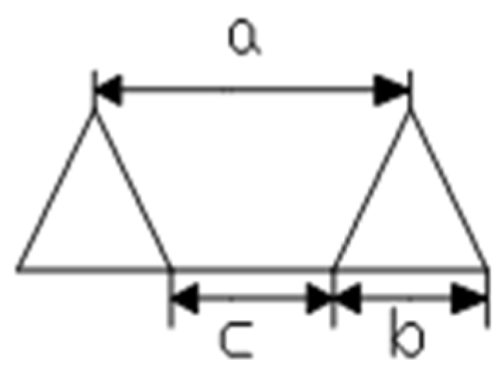
To verify the influence of various tooth spacings of the patch channel on the hydraulic performance, anticlogging performance, and energy dissipation performance of the emitters, a model that changed the size of the tooth spacing to optimize the patch channel was designed. It should be noted that the tooth spacing (a) is the sum of the tooth width (b) and the tooth base distance (c), so the change of the tooth spacing (a) will also cause the change of the tooth width (b) and the tooth base distance (c).
Taking No. 5 drip irrigation tape (NFD 16 × 300–1.38–0.18) widely used on the market as an example, the authors used Unigraphics NX and Soildworks 3D modeling software to narrow the tooth spacing to 0.1 mm, 0.2 mm, and 0.29 mm of the original size. Equation (2) illustrates the quantitative relationship among the tooth spacing (a), the tooth width (b), and the tooth base distance (c) of the emitter. The specific design sizes of the three parameters are shown in Table 3. Figure 4 shows the structure of the emitter tooth.
a = b + c
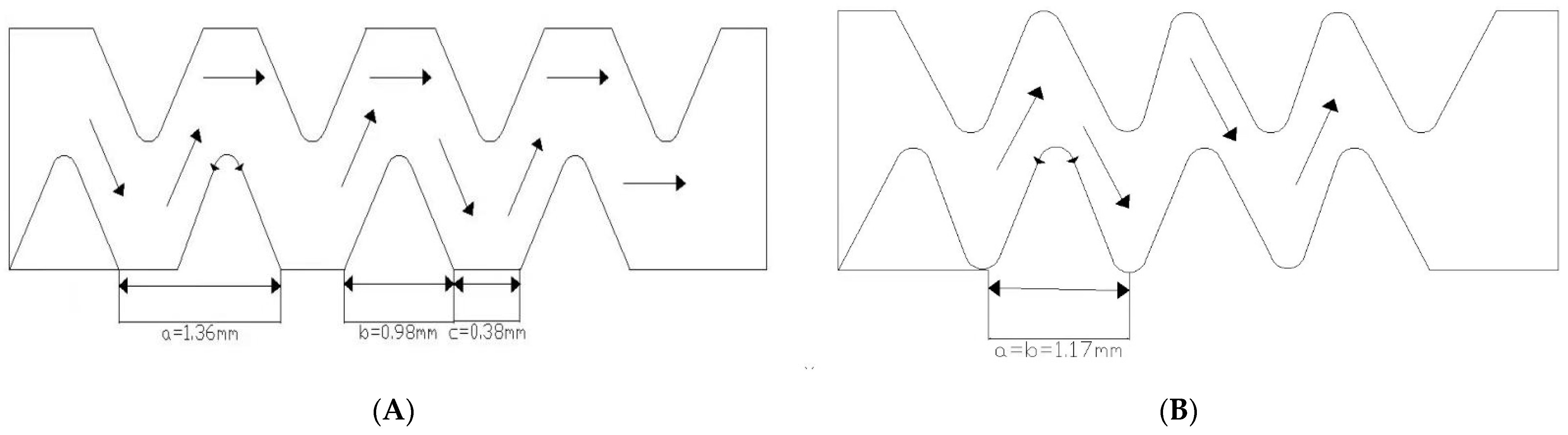
From Table 3, on the one hand, the tooth spacing in Plan 1, Plan 2, and Plan 3 is reduced, respectively, by 0.1, 0.2, and 0.29 mm, and the tooth base distance is reduced by 0.2, 0.4, and 0.58 mm, while the tooth width is increased correspondingly by 0.1, 0.2, and 0.29 mm. On the other hand, when the tooth spacing is reduced by 0.29–1.17 mm in Plan 3, the tooth width (b) is increased to 1.17 mm, and the tooth base distance (c) is reduced to 0 mm. This indicates that 0.29 mm is the limit of tooth spacing reduction. Therefore, the three plans actually represent two different flow channel types. One is the flow channel with a tooth base, such as Plan 1 and Plan 2. The other is the flow channel without a tooth base, such as Plan 3. Figure 5 is the structure diagram of the two drip irrigation channel types.
4. Numerical Simulation on the Studied Flow Channel
4.1. Basic Control Equations of Flow Field in CFD Software
The water flow in the patch channel is a constant incompressible liquid, and its motion law conforms to the law of conservation of mass and momentum. The basic control equations of the inner patch channel [28] consist of the continuity equation Formula (3) and the Navier–Stokes equation Formula (4).
where t is time, s; ux, uy, and uz are the velocity components in the x, y, and z coordinate axes; ρ is the density of the water, kg/m3; μ is the dynamic viscosity coefficient, Pa·s; p is the pressure, Pa; and Fx, Fy, and Fz are the components of the mass force; if the mass force is only gravity, then Fx = 0, Fy = 0, and Fz = ‒g.
4.2. Building the Numerical Simulation Model
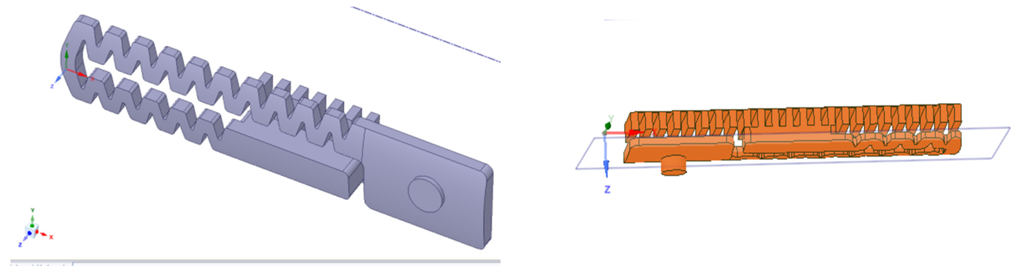
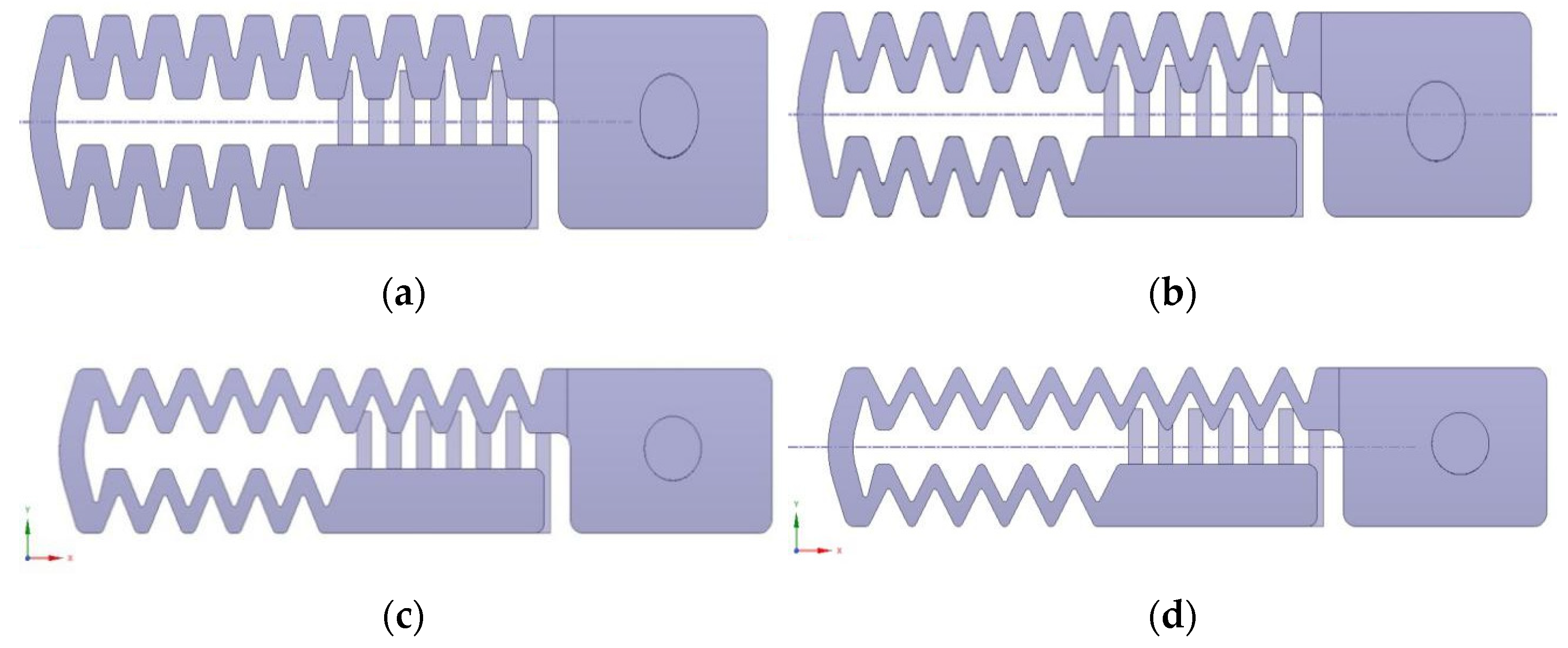
The 3D modeling software Spaceclaim was used to repair the 3D geometry of the patch channel to improve the mesh quality, and then, the fluid space of the channel, which is shown in Figure 6, could be established by Unigraphics NX and Soildworks. Figure 7 shows the comparison between the different optimization plans that are based on tooth spacing.
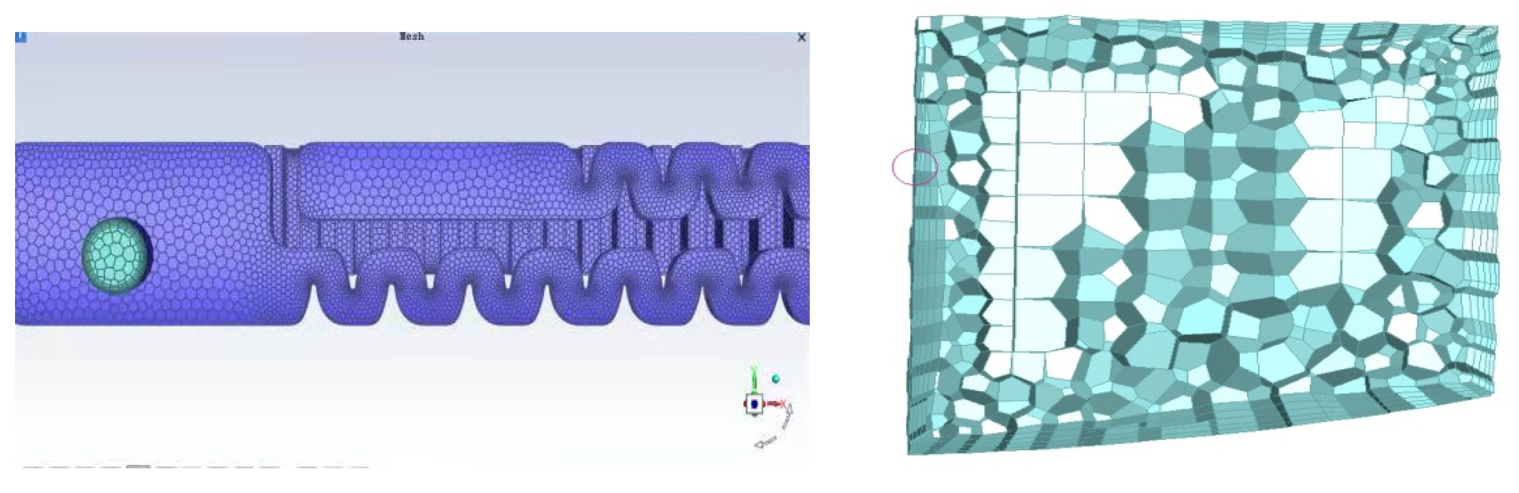
Due to the actual size of the fluid space, the mesh size in this article was set from 0.025 mm to 0.3 mm, and three grids were drawn with the minimum gap. The face meshing of the fluid space is shown in Figure 8. In addition, the authors refined and drew the body mesh with five layers at a ratio of 10:1 and set the body mesh shape to outer polyhedron and inner hexahedron. Finally, the water inlet, the water outlet, the pressure inlet, and the pressure outlet were connected, and the fluid space body mesh is shown in Figure 9.
According to the regression calculation of the pressure flow test data of 13 drip irrigation tapes, if the flux coefficient is close to 0.5, then the flow state of the fluid space in the flow channel is a turbulent flow. Observe whether the change of the flow and the residual state of the iteration in the subsequent iterations are stable through monitoring the mass flow at the outlet of the channel. In order to simulate the thickness of the drip irrigation tapes, an outlet hole with a diameter of 1.8 mm and a thickness of 0.18 mm is constructed in the water storage tank of the patch channel.
4.3. Numerical Simulation and Model Verification
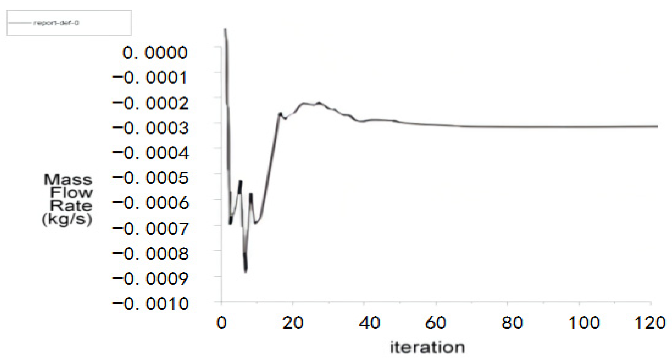
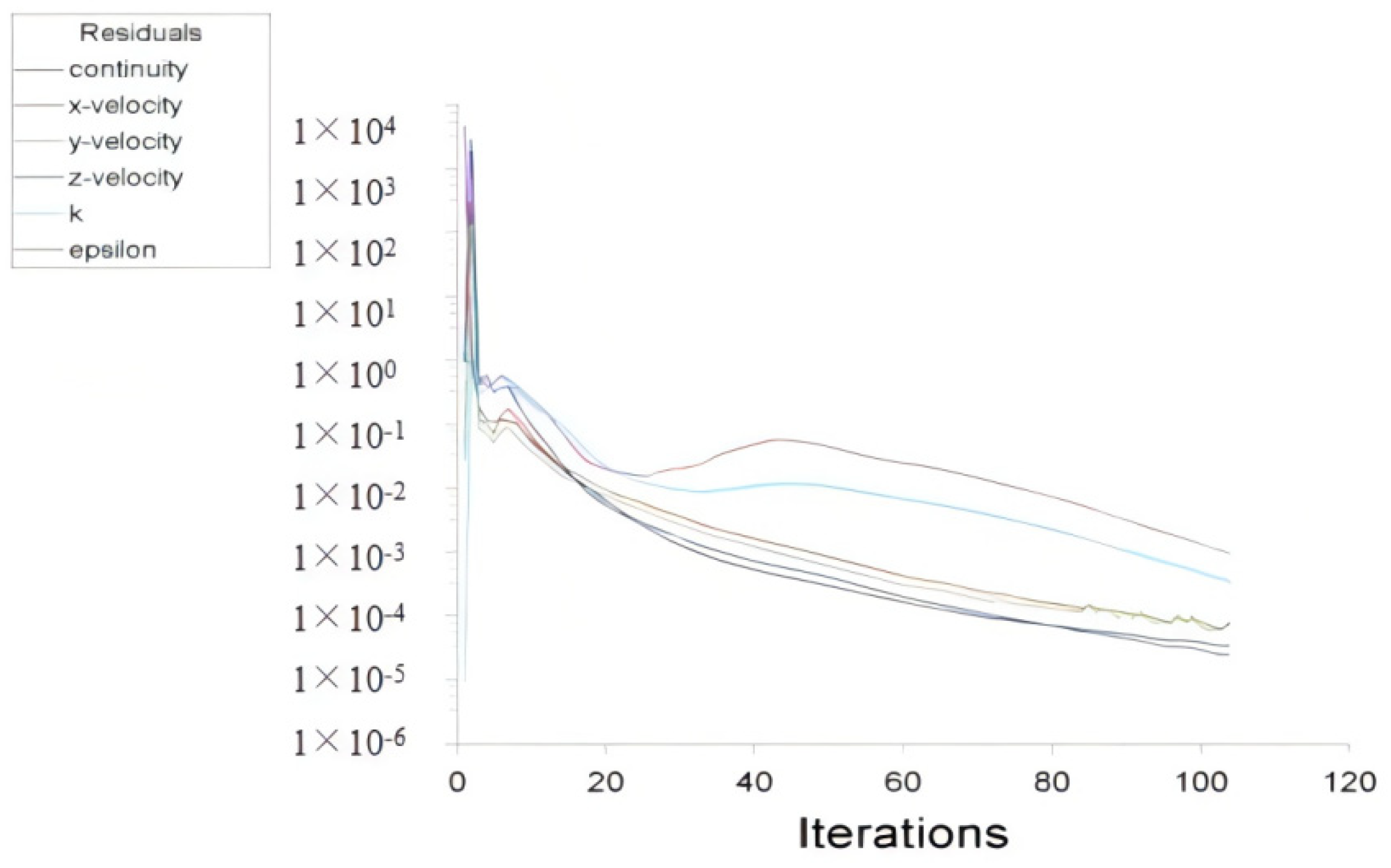
After the iterative numerical simulated calculation, the change curve of the mass flow diagram and the iterative residual are shown in Figure 10 and Figure 11, respectively. The simulation calculations did not end until the mass flow was stable and the residual was the smallest and stable.
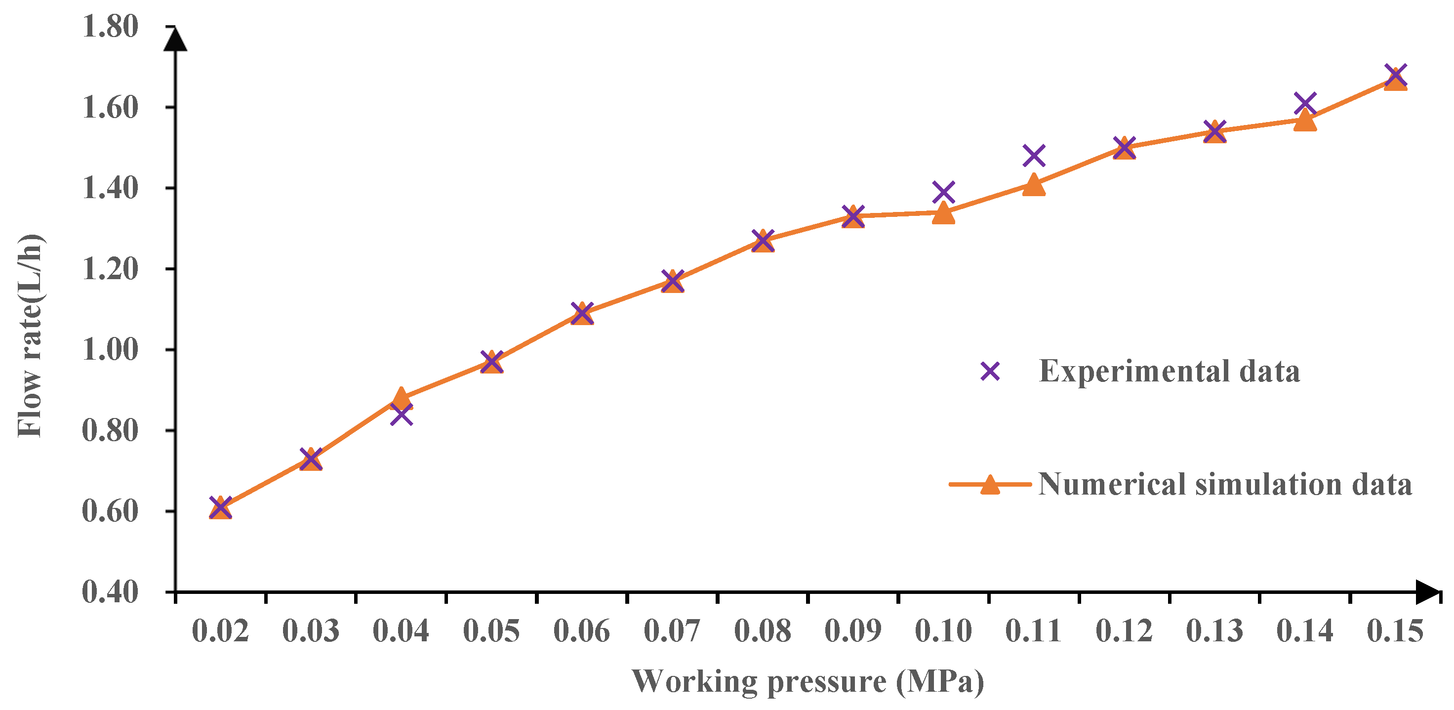
To verify the CFD simulations, a series of pressure flow rate tests on NO.5 drip irrigation tape (NFD 16 × 300-1.38-0.18) was conducted under the working pressure of 0.02–0.15 MPa. The results showed that the relative error between the experimental flow rate and the numerical simulated flow rate was −4.73% to 5.48%, with an average error of 2.68%. And as shown in Figure 12, the numerical simulated results basically coincided with the experimental flow rate. Therefore, the numerical simulation model established by CFD has a high accuracy, so that this model could replace the physical entity test within a certain working pressure range and provide theoretical support for the structural parameter optimization of the emitter and a study on the hydraulic performance and anticlogging energy dissipation effect. Most importantly, this method could reduce the cost and time invested in physical experiments.
5. Results and Discussion
5.1. Analysis of Energy Dissipation Performance for New Designed Emitters
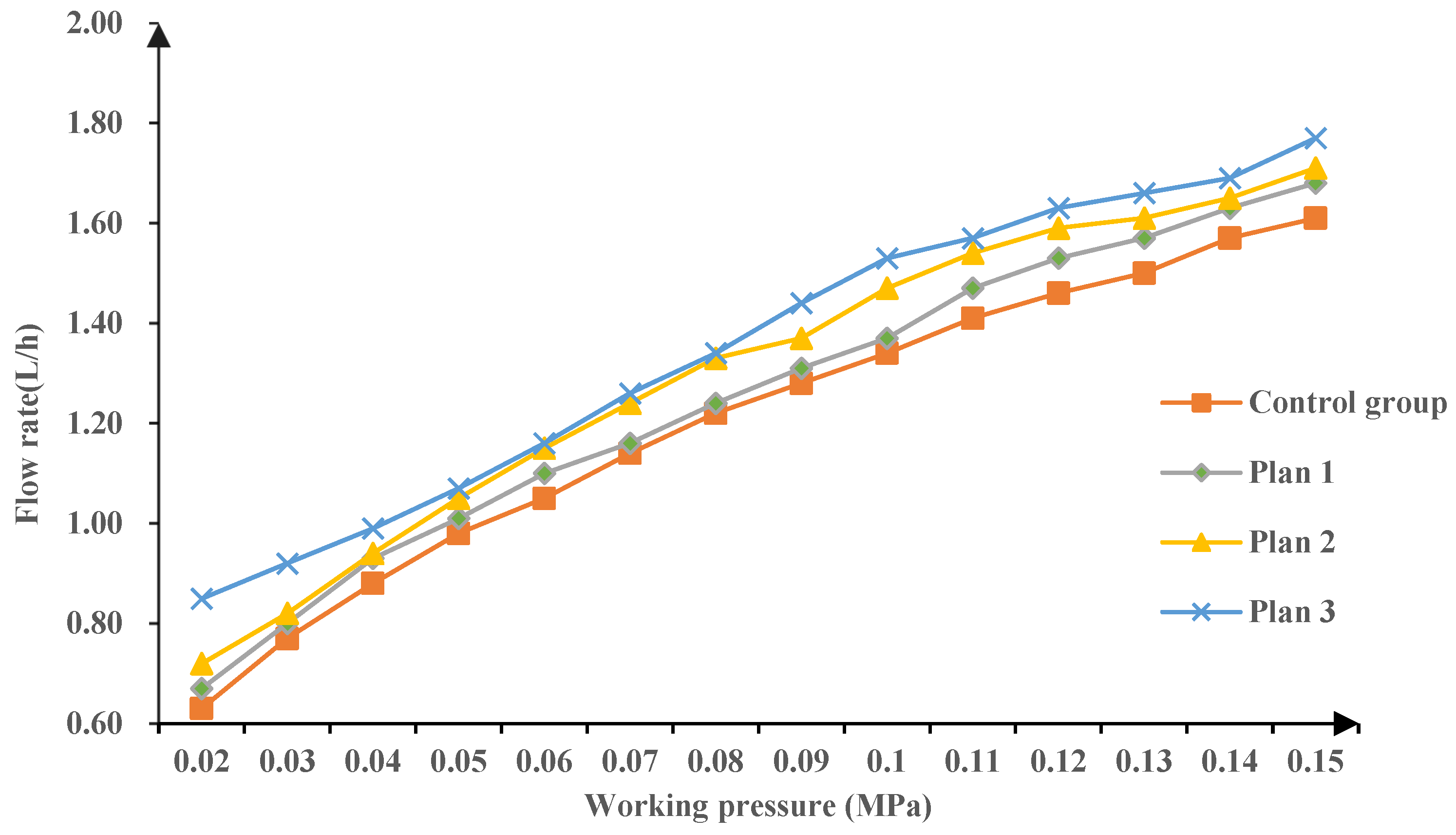
Using CFD to numerically simulate the flow rate of the drip irrigation emitters under the working pressure of 0.02–0.15 MPa, the authors found that (1) with the increase of the working pressure, the flow rate of the drip irrigation tape emitter increased, while the energy dissipation effect decreased successively. (2) The emitter flow rate in flow channel 1 with a tooth base (represented by Plans 1 and 2) and in flow channel 2 without a tooth base (represented by Plan 3) increased by 4.17%, 8.33%, and 12.50%, respectively, which shows that the emitter flow rate in flow channel 2 is better than flow channel 1 under the same working pressure. In conclusion, the simulation results demonstrated that there is a negative correlation between the emitter flow rate and the tooth spacing, which means that the smaller the tooth spacing is, the larger the emitter flow rate is and the worse the channel energy dissipation performance. Figure 13 shows the variations of the hydraulic characteristic curves for different emitter optimization plans, which confirmed the above conclusions.
5.2. Analysis of Hydraulic Performance (Flow Index) for New Designed Emitters
R software was used to analyze the test data and simulation results of the drip irrigation belt emitters, and we could calculate the flow coefficient and flow index on the basis of Formula (5). The calculation results are shown in Table 4.
where q is the flow rate of the emitter, L/h; H is the work pressure of the emitter, MPa; C is the flow coefficient; and x is the flow index [29].
q = CHx
From Table 4, it could be observed that the flow index of the emitters in the three plans decreased with the decrease in the tooth spacing, while the average flow rate of the emitter increased. Compared to the control group, the change rate of the flow index, flow coefficient, and average flow rate in Plan 3 were −14.50%, −5.08%, and 12.50%, respectively. Therefore, Plan 3 has the most obvious change when the tooth spacing is so small that the tooth base disappears. Generally, the smaller the flow index is, the better the hydraulic performance the patch channel has and the smaller effect on the emitter flow rate of the working pressure [30,31]. Through the comparative analysis to the hydraulic performance parameters in the three plans, we found that all the flow indexes were less than 0.5. This is mainly because of the decrease of the tooth spacing, which makes the patch channel width smaller and narrower, and the local head loss and turbulence intensity in the flow channel increase accordingly. Then, the flow index decreases with the decrease of the tooth spacing.
5.3. Analysis of Hydraulic Performance (Flow Field) for New Designed Emitters
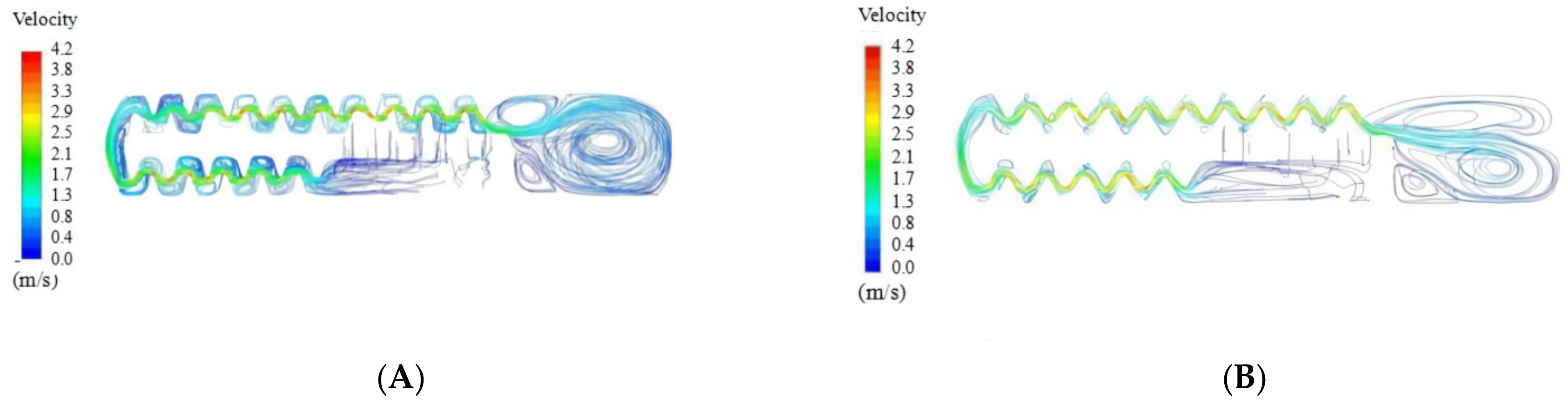
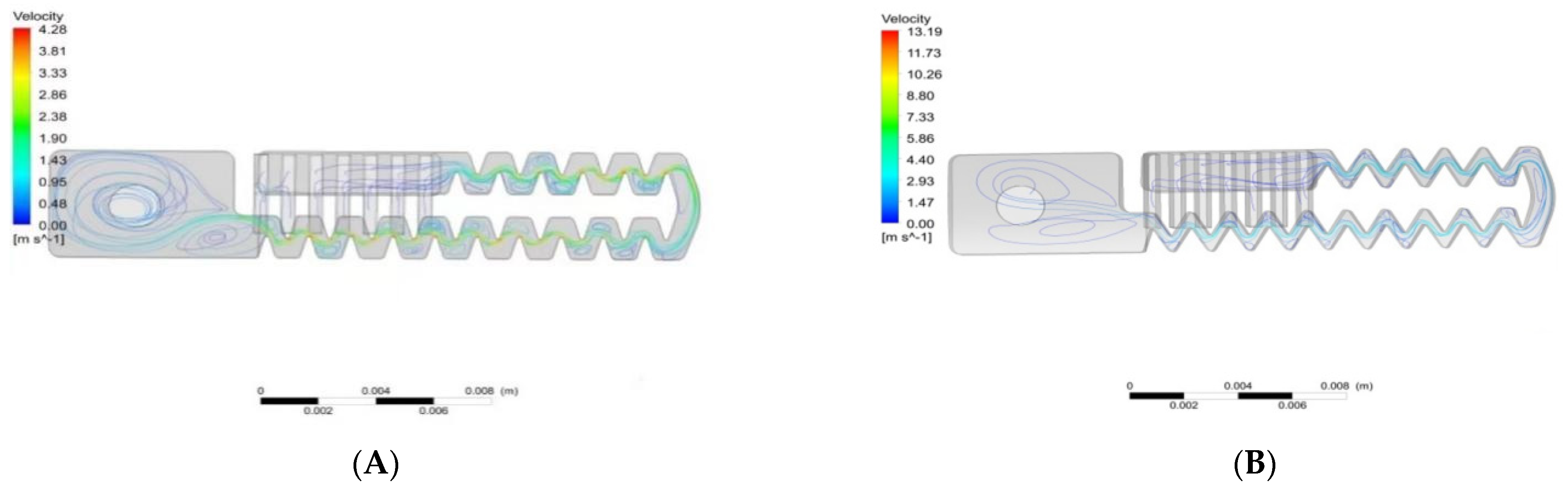
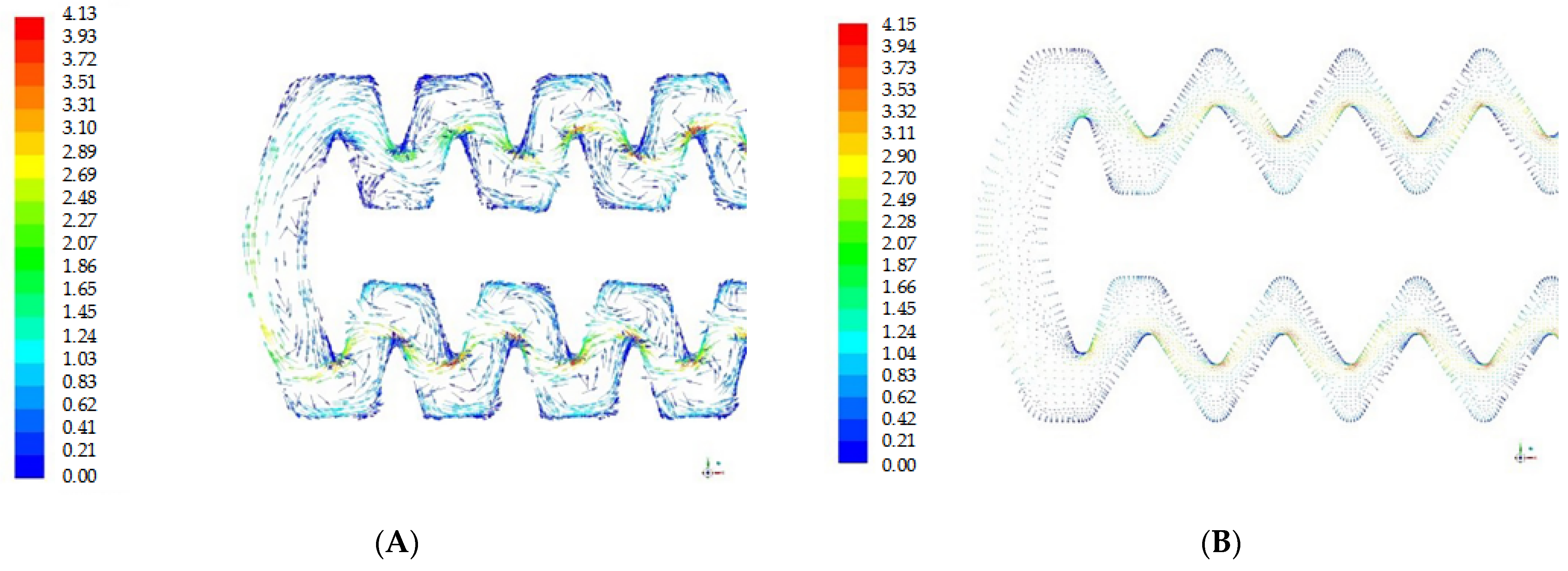
With the help of CFD and CFD-Post, schematic diagrams of the flow channel velocity under the working pressure of 0.1 MPa were drawn for Plan 3, such as the cloud diagram of the velocity distribution (Figure 14), the 3D diagram of the velocity distribution (Figure 15), and the flow channel velocity vector diagram (Figure 16), so as to further analyze the flow field characteristics of the optimized drip irrigation tape emitters. In the picture, the flow patterns of each unit of the patch channel are similar, which manifests as a larger flow velocity in the streamline-concentrated area, while it is smaller in the streamline-dispersed area. Comparing the pictures before and after optimization, it is found that the streamline is dense in the main flow area of the channel center, and the flow velocity is faster in this area, while the streamline in the boundary area between the teeth and the patch channel is sparse and vortexing occurs.
The vortex causes large fluctuations of the flow pattern in the channel, and the flow velocity in the channel decreases from the edge to the center of the vortex, resulting in a large local head loss [32,33]. The transient vortexing reduces the flow velocity and makes the turbulent flow energy of the channel becoming smaller [34]. Some suspended particles and debris are gradually precipitated, which seriously affects the hydraulic performance and anticlogging performance of the flow channel. Due to the reduction of the tooth spacing in Plan 3, the space for vortexing between the teeth were narrowed as well. Meanwhile, compared to the unoptimized emitters, the number and intensity of the vortexes in the optimized channel are smaller and the flow velocity is generally increased by 3 m/s from 2.3 to 4.1 m/s, becoming more uniform. In other words, the hydraulic performance of the flow channel in Plan 3 was improved with the optimization of the tooth spacing.
5.4. A Summary of Performance Analysis for New Designed Emitters
From the analysis of the hydraulic performances and energy dissipation performances in the all plans, it could be found that the smaller the tooth spacing was, the better the hydraulic performance of the channel was, and the lower the energy dissipation performance.
According to the comparison of the flow index and average flow rate of the emitters in the three plans, the decrease of the flow index was smaller than the increase of the average flow rate of the emitters in Plans 1 and 2, and the change ratios of the two parameters were 1:3.21 and 1:2.56, respectively, while it was 1.16:1 in Plan 3. This reflects that the improvement of hydraulic performance was greater than the reduction of the energy dissipation performance. Therefore, Plan 3 was the best in all plans. In other words, flow channel 2 without a tooth base represented by Plan 3 had a better performance than flow channel 1 with a tooth base.
5.5. Discussion
The structural parameters of the flow channel play a key role in the drip emitter performance [35,36,37]. In this article, the structural parameters that affect the hydraulic performance of the drip irrigation tape were analyzed by Principal Component Analysis (PCA). The results showed that the influence of each structural parameter was: tooth spacing > minimum channel width > tooth height > maximum channel width > tooth numbers > channel circumference > channel depth > tooth arc length, of which the influence of tooth spacing was the first. This was consistent with the conclusions of Wang et al. [14] and Chang et al. [38] when they studied the influence of structural parameters on the comprehensive performance of drip irrigation emitters. Zhang et al. [15] used the method of combining an orthogonal test and CFD numerical simulation technology to analyze and evaluate the three parameters of tooth width, tooth base distance, and tooth height. The main reason is that the flow behavior of water passing through the channel can be observed by CFD, and the analysis of the structural parameters is more precise and accurate. Based on 18 drip irrigation tapes, the most important parameter was selected from the eight main patch channel structural parameters, which contained most of the channel structural parameters. Therefore, in a statistical sense, the results of this paper were reliable.
Taking the tooth spacing of key structural parameters as the optimization object, three plans were designed to analyze the hydraulic performance and energy dissipation performance of the optimized channel. The smaller the flow index of the channel, the better the hydraulic performance [39]. It was found that, after optimization, all the flow index of the channel was reduced. The flow index of Plan 3 was the smallest at 0.395. The improvement in the hydraulic performance was greater than the reduction in the energy dissipation performance. The vortex between the saw teeth was reduced, which improved the kinetic energy and decreased the clogging degree of the patch channel. In the simulation study of the maze drip irrigation emitter by Zhang et al. [40], they mainly analyzed the anticlogging performance of the emitter from the changes in the eddy and low-speed areas of the flow field of the channel. The conclusion was that the reduction of the eddy current and flow velocity will depose of the sediment and other impurities. Therefore, the view of Zhang supports this conclusion of this article. Additionally, in this paper (1), when constructing the geometry of the emitter, a water outlet hole was added to the outlet of the water storage tank to simulate drip irrigation, which improved the accuracy of the numerical simulation. (2) The comparative analysis of the energy dissipation performance and flow index of the emitters of each plan were added, which were more reliable for the analysis of the water flow change in the emitter flow channel after optimizing the tooth spacing. (3) The flow state of the water in the optimized channels through the characteristics of velocity distribution, streamline velocity, and others was also shown. This feature makes it more comprehensive to analyze the hydraulic performance of the optimized emitters. At the same time, a reasonable inference could be made on the anticlogging performance of the flow channel: the narrower tooth spacing in Plan 3 caused the small channel cross area, which may have had a certain effect on the ability of the particles to pass through the corners of the tooth tip. However, the main flow velocity and kinetic energy of the flow channel also increased, and the flow channel width was always larger than the particle diameter; then, the clogging degree of the channel could be greatly decreased. It is worth mentioning that more research on the numerical simulation of the solid–liquid two-phase flow in the patch channel could be carried out in the future to further verify this inference.
6. Conclusions
The results showed that, among the eight selected channel structure parameters, tooth spacing was regarded as the most critical structural parameter that affects the performance of the channel. Therefore, the authors proposed three kinds of plans by reducing the tooth spacing to optimize the comprehensive performance of the channel emitters. Further, the three plans were divided into two flow channel types on the basis of the different tooth base characteristics. Flow channel 1 with a tooth base was represented by Plan 1 and Plan 2, and flow channel 2 without a tooth base was represented by Plan 3.
Carrying out a numerical simulation of the patch channel in the three plans, it could be concluded as follows: (1) Using CFD (FLUENT) to set the boundary conditions for adding water holes to the patch channel storage tank, an outflow model of drip irrigation tape was established to simulate numerically the relationship between the work pressure and flow rate of No. 5 tape. As a result, it was found that the error range between the test data and the simulated data through the FLUENT solver was −4.73%~5.48%, and the average error rate was 2.68%. The numerical simulation results were basically consistent with the test. The No. 5 tape numerical simulation model established by CFD (fluent) was more accurate. (2) With the reduction of the tooth spacing in Plan 3, its energy dissipation performance was weakened as well. The hydraulic performance of each optimized plan was analyzed from the aspects of the flow index and flow field characteristics. The results showed that Plan 3 had the best hydraulic performance, because its flow index was the smallest (0.395), and the degree and number of vortices in the channel were small, and the flow rate was more uniform. The improvement of the hydraulic performance was greater than the reduction of the energy dissipation performance with the ratio of the flow index and average flow rate of the emitters was 1.16:1. To sum up, Plan 3 was the best among all the plans. (3) In conclusion, this article provides a new direction for improving the boundary conditions of the model and improving the accuracy of the numerical simulation. When other conditions are certain, the reduction of the tooth spacing is beneficial to improve the hydraulic performance of the emitter and save the production cost. The results could provide a theoretical induction for inner drip irrigation tape application and production.
Author Contributions
Methodology, data curation, formal analysis, and writing—original draft, W.Z.; conceptualization, validation, supervision, and project administration, L.Y.; software, visualization, and investigation, J.W.; and writing—review and editing, X.Z. All authors have read and agreed to the published version of the manuscript.
Funding
The work was supported by the National Natural Science Foundation of China (No. 52179052).
Institutional Review Board Statement
Not applicable.
Informed Consent Statement
Not applicable.
Data Availability Statement
The data presented in this study are available on request from the corresponding author.
Conflicts of Interest
The authors declare no conflict of interest.
References
- Li, Y. Effects of fractal flow path designing and its parameters on emitter hydraulic performance. Chin. J. Mech. Eng. 2007, 43, 109–114. [Google Scholar] [CrossRef]
- Wei, Q.; Shi, Y.; Dong, W.; Lu, G.; Huang, S. Study on hydraulic performance of drip emitters by computational fluid dynamics. J. Agric. Water Manag. 2006, 84, 130–136. [Google Scholar] [CrossRef]
- Wang, Y.; Ju, X.; Zhu, S.; Li, M. Simulation of local head loss of drip-irrigation tape with integrated in-line emitters as a function of cross section. J. Span. J. Agric. Res. 2020, 18, e0210. [Google Scholar] [CrossRef]
- Zhou, L.; Tao, H.; Li, Q.; Ainemat, M.; Yang, W.; Jiang, Y.; Li, S. Research on the influencing factors of hydraulic performance of inlay patch drip irrigation tape. J. Water Sav. Irrig. 2020, 11, 25–28, (In Chinese with English abstract). [Google Scholar]
- Zhang, C.; Kang, Y.; Jiang, S.; Wan, S.; Liu, S. Assessment of hydraulic performance of drip-irrigation emitters at low head pressures. J. Irrig. Drain. Eng. 2011, 137, 730–734. [Google Scholar] [CrossRef]
- Zhang, J.; Zhao, W.; Lu, B. Rapid prediction of hydraulic performance for emitters with labyrinth channels. J. Irrig. Drain. Eng. 2013, 139, 414–418. [Google Scholar] [CrossRef]
- Li, Y.; Feng, J. Progress in measurement of hydrodynamic characteristics in drip irrigation emitters. J. Drain. Irrig. Mach. Eng. 2014, 32, 86–92. [Google Scholar]
- Hezarjaribi, A.; Dehghani, A.A.; Meftah Helgni, M.; Kiani Reza, A. Hydraulic performances of various trickle irrigation emitters. J. Agron. 2008, 7, 265–271. [Google Scholar] [CrossRef] [Green Version]
- Xing, S.; Wang, Z.; Zhang, J.; Liu, N.; Zhou, B. Simulation and verification of hydraulic performance and energy dissipation mechanism of perforated drip irrigation emitters. J. Water 2021, 13, 171. [Google Scholar] [CrossRef]
- Wu, D.; Li, Y.; Liu, H.; Yang, P.; Sun, H.; Liu, Y. Simulation of the flow characteristics of a drip irrigation emitter with large eddy methods. Math. Comput. Model. 2013, 58, 497–506. [Google Scholar] [CrossRef]
- Xu, T.; Zhang, L. Influence and analysis of structure design and optimization on the performance of a pit drip irrigation emitter. J. Irrig. Drain. Eng. 2020, 69, 633–645. [Google Scholar] [CrossRef]
- Li, G.; Wang, J.; Mahbub, A. Influence of geometrical parameters of labyrinth flow path of drip emitters on hydraulic and anti-clogging performance. J. Trans. ASABE 2016, 49, 637–643. [Google Scholar] [CrossRef]
- Tian, J.; Bai, D.; Ren, C.; Wang, X. Analysis on hydraulic performance of bidirectional flow channel of drip irrigation emitter. J. Trans. CSAE 2013, 29, 89–94. [Google Scholar]
- Wang, J. Study on the Hydraulic and Anti-Clogging Performance of Emitters. Master’s Thesis, China Agricultural University, Beijing, China, 2004. (In Chinese with English abstract). [Google Scholar]
- Zhang, L.; Li, S. Numerical experimental investigation of douche hydraulic performance on drip irrigation of tooth-type labyrinth channel. J. Water Resour. Power 2017, 35, 103–106, (In Chinese with English abstract). [Google Scholar]
- Ma, C.; Wei, Z.; Ma, S.; Chen, X.; Ma, J.; Chen, Z. Numerical simulation of a variable-curvature labyrinth channel emitter. J. Water Sav. Irrig. 2018, 11, 94–97, 106, (In Chinese with English abstract). [Google Scholar]
- Tian, J.; Bai, D.; Yu, F.; Wang, X.; Guo, L. Numerical simulation of hydraulic performance on bidirectional flow channel of drip irrigation emitter using Fluent. Trans. CSAE 2014, 30, 65–71, (In Chinese with English abstract). [Google Scholar]
- Zhangzhong, L.; Yang, P.; Ren, S.; Liu, Y.; Li, Y. Flow characteristics and pressure-compensating mechanism of non-pressure-compensating drip irrigation emitters. J. Irrig. Drain. Eng. 2015, 64, 637–646. [Google Scholar] [CrossRef]
- Al-Muhammad, J.; Tomas, S.; Anselmet, F. Modeling a weak turbulent flow in a narrow and wavy channel case of micro-irrigation. J. Irrig. Sci. 2016, 34, 1–17. [Google Scholar] [CrossRef]
- Zhou, W.; Zhang, L.; Wu, P.; Cai, Y.; Zhao, X.; Yao, C. Hydraulic performance and parameter optimization of a microporous ceramic emitter using computational fluid dynamics, artificial neural network and multi-objective genetic algorithm. J. Biosyst. Eng. 2020, 189, 11–23. [Google Scholar] [CrossRef]
- Wang, X.; Jin, B.; Fan, E.; Yao, J.; Zhang, C.; Wang, X.; Xue, Z. Effects of high frequency pulse produced by jet tee on hydraulic and anti-clogging characteristics of emitters. J. Trans. CASE 2020, 36, 113–119, (In Chinese with English abstract). [Google Scholar]
- Sun, H.; Li, Y.; Ji, F.; Liu, H.; Liu, Y. Effects of flow path boundary optimizations on particle transport in drip irrigation emitters. J. Irrig. Drain. Eng. 2016, 65, 417–425. [Google Scholar]
- Ma, X.; Gong, S.; Wang, J.; Yu, Y. Anti-clogging performance of dental labyrinth emitters under rated pressure and low operating pressure. J. Trans. CASE 2011, 42, 86–90, (In Chinese with English abstract). [Google Scholar]
- Bouhali, M.E.; Ouarriche, H.; Bouisfi, F.; Chaoui, M. Clogging investigation of pressure compensating button emitters: An experimental study of four types. J. Environ. Sci. Pollut. Res. 2020, 27, 44325–44332. [Google Scholar] [CrossRef] [PubMed]
- Wang, J.; Gong, S.; Li, G.; Zhao, Y. The influence of geometrical parameters of dental flow passage of labyrinth emitter on the hydraulic performance under low working pressure. J. Hydraul. Eng. 2014, 45, 72–78, (In Chinese with English abstract). [Google Scholar]
- Li, Y.; Yang, P.; Ren, S. General review on several fundamental points of design theory about flow path in drip irrigation emitters. J. Trans. CSAM 2006, 37, 145–149, (In Chinese with English abstract). [Google Scholar]
- Wang, X.; Bai, D.; Song, L.; Guo, L.; Li, J.; Wu, S. Contrast experiment on anti-clogging performance of bidirectional flow channel emitters with different structures in drip irrigation. J. Trans. CASE 2018, 34, 78–85, (In Chinese with English abstract). [Google Scholar]
- Wang, F. Computational Fluid Dynamics Analysis: Principles and Applications of CFD Software; Tsinghua University Press: Beijing, China, 2004. [Google Scholar]
- Keller, J.; Karmeli, D. Trickle irrigation design parameters. Trans. ASAE 1974, 17, 0678–0684. [Google Scholar] [CrossRef]
- Baghel, Y.K.; Kumar, J.; Patel, V.K. CFD analysis of the flow characteristics of in-line drip emitter with different labyrinth channels. J. Inst. Eng. India Ser. A 2021, 102, 111–119. [Google Scholar] [CrossRef]
- Sun, B.; Zhu, S.; Yang, L.; Liu, Q.; Zhang, C.; Zhang, J. Experimental and numerical investigation of flow measurement mechanism and hydraulic performance on curved flume in rectangular channel. Arab. J. Sci. Eng. 2020, 46, 4409–4420. [Google Scholar] [CrossRef]
- Feng, J.; Li, Y.; Wang, W.; Xue, S. Effect of optimization forms of flow path on emitter hydraulic and anti-clogging performance in drip irrigation system. J. Irrig. Sci. 2018, 36, 37–47. [Google Scholar] [CrossRef]
- Wang, C.; Li, Z.; Ma, J. Influence of emitter structure on its hydraulic performance based on the vortex. J. Agric. 2021, 11, 508. [Google Scholar] [CrossRef]
- Avner, A.; Mollie, S. Dripper-Clogging Factors in Wastewater Irrigation. J. Irrig. Drain. Eng. 1991, 117, 813. [Google Scholar]
- Karmeli, D. Classification and flow regime analysis of drippers. J. Agric. Eng. Res. 1977, 22, 165–173. [Google Scholar] [CrossRef]
- Zhangzhong, L.; Yang, P.; Li, Y.; Ren, S. Effects of flow path geometrical parameters on flow characteristics and hydraulic performance of drip irrigation emitters. J. Irrig. Drain. Eng. 2016, 65, 426–438. [Google Scholar] [CrossRef]
- Wang, F.; Wang, W. Research progress in analysis of flow passage in irrigation emitters using Computational Fluid Dynamics techniques. J. Trans. CASE 2006, 22, 188–192, (In Chinese with English abstract). [Google Scholar]
- Chang, Y.; Niu, W.; Wang, W. Numerical simulation and flow analysis of labyrinth path of drip irrigation emitters. J. Northwest A F Univ. (Nat. Sci. Ed.) 2009, 37, 203–207, (In Chinese with English abstract). [Google Scholar]
- Guo, L.; Bai, D.; Wang, X.; He, J.; Zhou, W.; Cheng, P. Hydraulic performance and energy dissipation effect of two-ways mixed flow emitter in drip irrigation. J. Trans. CASE 2016, 32, 77–82, (In Chinese with English abstract). [Google Scholar]
- Zhang, Q.; Ye, H.; Yao, G. Numerical simulation of drip emitter channel. J. Agric. Mech. Res. 2012, 34, 190–194, (In Chinese with English abstract). [Google Scholar]
Figure 1.
Schematic diagram of the drip irrigation tape model number.

Figure 2.
Schematic diagram of the hydraulic performance test setup and its connections.

Figure 3.
Schematic diagram of the flow channel structure of the inner patch drip irrigation tape. (A) Main view of the emitter channel; (B) profile view of the emitter channel.
Figure 3.
Schematic diagram of the flow channel structure of the inner patch drip irrigation tape. (A) Main view of the emitter channel; (B) profile view of the emitter channel.

Figure 4.
The structure diagram of the tooth base distance, width, and tooth spacing in the flow channel of the emitter. The letter a is the tooth spacing, b is tooth width and c is tooth base distance, mm.
Figure 4.
The structure diagram of the tooth base distance, width, and tooth spacing in the flow channel of the emitter. The letter a is the tooth spacing, b is tooth width and c is tooth base distance, mm.

Figure 5.
The structure diagram of the two drip irrigation channel types. The arrow represents the size of the parameters. (A) Flow channel 1 (with a tooth base). (B) Flow channel 2 (without a tooth base).
Figure 5.
The structure diagram of the two drip irrigation channel types. The arrow represents the size of the parameters. (A) Flow channel 1 (with a tooth base). (B) Flow channel 2 (without a tooth base).

Figure 6.
The fluid space of the drip irrigation channel.

Figure 7.
The comparison diagram of all the optimization plans based on tooth spacing. (a) Control group (tooth spacing is 1.46 mm), (b) Plan 1 (tooth spacing is 1.36 mm), (c) Plan 2 (tooth spacing is 1.26 mm), and (d) Plan 3 (tooth spacing is 1.17 mm).
Figure 7.
The comparison diagram of all the optimization plans based on tooth spacing. (a) Control group (tooth spacing is 1.46 mm), (b) Plan 1 (tooth spacing is 1.36 mm), (c) Plan 2 (tooth spacing is 1.26 mm), and (d) Plan 3 (tooth spacing is 1.17 mm).

Figure 8.
The face meshing of the fluid space.

Figure 9.
The fluid space body mesh and internal mesh.

Figure 10.
Mass flow report graph.

Figure 11.
Convergence curve of iterative computations.

Figure 12.
Hydraulic characteristic curves of the practical experiment and numerical simulations with NO.5 drip irrigation tape.
Figure 12.
Hydraulic characteristic curves of the practical experiment and numerical simulations with NO.5 drip irrigation tape.

Figure 13.
The variations of the hydraulic characteristic curves for different emitter optimization plans.
Figure 13.
The variations of the hydraulic characteristic curves for different emitter optimization plans.

Figure 14.
Cloud diagram of the velocity distribution of the flow channel for 0.1 MPa. (A) Streamline velocity distribution in the control group. (B) Streamline velocity distribution in Plan 3.
Figure 14.
Cloud diagram of the velocity distribution of the flow channel for 0.1 MPa. (A) Streamline velocity distribution in the control group. (B) Streamline velocity distribution in Plan 3.

Figure 15.
Three−dimensional diagram of the velocity distribution of the flow channel for 0.1 MPa. (A) Control group (before optimization). (B) Plan 3 (after optimization).
Figure 15.
Three−dimensional diagram of the velocity distribution of the flow channel for 0.1 MPa. (A) Control group (before optimization). (B) Plan 3 (after optimization).

Figure 16.
Velocity vector diagram of the flow channel for 0.1 MPa. (A) Control group (before optimization). (B) Plan 3 (after optimization).
Figure 16.
Velocity vector diagram of the flow channel for 0.1 MPa. (A) Control group (before optimization). (B) Plan 3 (after optimization).


Table 1.
Product parameters of the emitter of the drip irrigation tape samples.
| Drip Irrigation Tape | Maximum Channel Width (mm) | Channel Depth (mm) | Tooth Numbers | Tooth Spacing (mm) | Tooth Height (mm) | Channel Circumference (mm) | Tooth Arc Length (mm) | Minimum Channel Width (mm) |
|---|---|---|---|---|---|---|---|---|
| NFD 12 × 300–1.38–0.4 | 0.811 | 0.432 | 49 | 1.50 | 0.942 | 145.498 | 0.258 | 0.538 |
| NFD 16 × 300–1.38–0.18 | 0.831 | 0.370 | 29 | 1.40 | 0.794 | 86.330 | 0.266 | 0.532 |
| NFD 20 × 300–1.38–0.2 | 0.811 | 0.382 | 49 | 1.50 | 0.871 | 145.669 | 0.258 | 0.538 |
| NFD 16 × 300–1.38–0.18 | 0.885 | 0.401 | 31 | 1.50 | 0.965 | 95.974 | 0.257 | 0.466 |
| NFD 16 × 300–1.38–0.18 | 0.870 | 0.748 | 31 | 1.46 | 0.945 | 95.375 | 0.214 | 0.573 |
| NFD 16 × 300–2–0.18 | 0.964 | 0.702 | 25 | 1.60 | 0.759 | 83.358 | 0.158 | 0.737 |
| NFD 16 × 300–2.2–0.18 | 0.669 | 0.998 | 39 | 1.80 | 0.984 | 129.969 | 0.251 | 0.614 |
| NFD 16 × 300–2.2–0.18 | 0.765 | 0.907 | 39 | 1.80 | 0.964 | 129.105 | 0.263 | 0.709 |
| NFD 16 × 300–2.3–0.18 | 1.036 | 0.651 | 26 | 1.80 | 0.970 | 89.060 | 0.261 | 0.738 |
| NFD 20 × 100–2.5–0.2 | 0.884 | 0.592 | 21 | 2.24 | 1.026 | 82.506 | 0.253 | 0.881 |
| NFD 16 × 300–2.5–0.18 | 0.902 | 0.445 | 21 | 2.20 | 1.000 | 80.228 | 0.291 | 0.864 |
| NFD 16 × 300–2.7–0.18 | 0.988 | 0.408 | 23 | 2.2 | 1.080 | 90.163 | 0.293 | 0.904 |
| NFD 16 × 300–2.8–0.18 | 1.004 | 0.709 | 23 | 2 | 0.950 | 85.404 | 0.252 | 0.837 |
| NFD 16 × 300–3–0.2 | 1.004 | 0.608 | 29 | 2.25 | 0.688 | 106.690 | 0.267 | 0.916 |
| NFD 16 × 300–3–0.18 | 1.899 | 0.998 | 22 | 1.6 | 1.974 | 101.986 | 0.252 | 0.579 |
| NFD 16 × 200–3–0.2 | 2.229 | 0.782 | 22 | 1.6 | 1.963 | 105.101 | 0.259 | 0.633 |
| NFD 16 × 300–3–0.18 | 0.970 | 0.836 | 29 | 2.28 | 0.779 | 113.490 | 0.258 | 0.841 |
| NFD 16 × 300–5–0.2 | 0.768 | 0.368 | 37 | 1.6 | 0.684 | 99.144 | 0.251 | 0.649 |
Table 2.
The principal component matrix of four principal elements and the score of each structural parameter.
Table 2.
The principal component matrix of four principal elements and the score of each structural parameter.
| Comp. 1 | Comp. 2 | Comp. 3 | Comp. 4 | Score | |
|---|---|---|---|---|---|
| Tooth spacing | 0.438 | −0.346 | 0.299 | −0.187 | 33.265 |
| Minimum channel width | 0.451 | −0.343 | 0.148 | −0.238 | 31.883 |
| Tooth height | 0.182 | 0.568 | 0.258 | 0.132 | 29.579 |
| Maximum channel width | 0.231 | 0.551 | 0.123 | 0.144 | 28.717 |
| Tooth numbers | 0.552 | −0.116 | 0.260 | −0.115 | 28.670 |
| Channel circumference | 0.422 | 0.035 | 0.545 | −0.264 | 28.469 |
| Channel depth | 0.145 | 0.314 | 0.160 | −0.725 | 27.343 |
| Tooth arc length | 0.120 | −0.153 | 0.646 | 0.510 | 26.608 |
Table 3.
Channel physical optimization plans of the emitter.
| Plans | Tooth Spacing a (mm) | Tooth Width b (mm) | Tooth Base Distance c (mm) |
|---|---|---|---|
| Control group | 1.46 | 0.88 | 0.58 |
| Plan 1 | 1.36 | 0.98 | 0.38 |
| Plan 2 | 1.26 | 1.08 | 0.18 |
| Plan 3 | 1.17 | 1.17 | 0.00 |
Table 4.
The comparison of the hydraulic performance of the emitters in all the plans.
| Plans | Flow Index | Compare to the Control Group | Flow Coefficient | Compare to the Control Group | Average Flow Rate (L/h) | Compare to the Control Group |
|---|---|---|---|---|---|---|
| Control group | 0.462 | 0.00% | 3.881 | 0.00% | 1.20 | 0.00% |
| Plan 1 | 0.456 | −1.30% | 3.975 | 2.42% | 1.25 | 4.17% |
| Plan 2 | 0.447 | −3.25% | 4.043 | 4.17% | 1.30 | 8.33% |
| Plan 3 | 0.395 | −14.50% | 3.684 | −5.08% | 1.35 | 12.50% |
Publisher’s Note: MDPI stays neutral with regard to jurisdictional claims in published maps and institutional affiliations. |
© 2022 by the authors. Licensee MDPI, Basel, Switzerland. This article is an open access article distributed under the terms and conditions of the Creative Commons Attribution (CC BY) license (https://creativecommons.org/licenses/by/4.0/).
Share and Cite
MDPI and ACS Style
Zhang, W.; Yang, L.; Wang, J.; Zhang, X. Analysis of Flow Channel Structure Parameter and Optimization Study on Tooth Spacing of Drip Irrigation Tape. Water 2022, 14, 1694. https://doi.org/10.3390/w14111694
AMA Style
Zhang W, Yang L, Wang J, Zhang X. Analysis of Flow Channel Structure Parameter and Optimization Study on Tooth Spacing of Drip Irrigation Tape. Water. 2022; 14(11):1694. https://doi.org/10.3390/w14111694
Chicago/Turabian StyleZhang, Weiting, Luhua Yang, Jinyi Wang, and Xinhua Zhang. 2022. "Analysis of Flow Channel Structure Parameter and Optimization Study on Tooth Spacing of Drip Irrigation Tape" Water 14, no. 11: 1694. https://doi.org/10.3390/w14111694
Note that from the first issue of 2016, this journal uses article numbers instead of page numbers. See further details here.