Article

Conceptualization and Prototype of an Anti-Erosion Sensing Revetment for Levee Monitoring: Experimental Tests and Numerical Modeling

1
Civil and Environmental Engineering Department, Politecnico di Milano, Piazza Leonardo da Vinci, 32, 20133 Milano, Italy
2
Fondazione Politecnico di Milano, Piazza Leonardo da Vinci, 32, 20133 Milano, Italy
3
Studio di Ingegneria Civile e Ambientale ChiariniAssociati, Via Galileo Ferraris, 63, 52100 Arezzo, Italy
4
Cohaerentia Srl, Via Pinturicchio 5, 20131 Milano, Italy
5
Maccaferri Innovation Center, Via Ipazia, 2, 39100 Bolzano, Italy
*
Author to whom correspondence should be addressed.
Water 2020, 12(11), 3025; https://doi.org/10.3390/w12113025
Submission received: 28 September 2020 / Revised: 24 October 2020 / Accepted: 26 October 2020 / Published: 28 October 2020
(This article belongs to the Special Issue New Paradigms in Flood Hazard and Risk Management)

Abstract

:
The problem of levee embankment control during high flows is crucial for flood risk management in floodplains. Levee defense lines are often hundreds of kilometers long and surveys during emergencies are not easy tasks. For these reasons, levees monitored with in situ sensors and a suitable Information Technology (IT) real-time data communication and integration infrastructure, so-called “smart levees”, are gaining increasing interest as a crucial protection technology in floodplains. The paper presents the conceptualization of a prototype of a levee smart revetment, based on the integration of an optical fiber (OF) cable into a steel double-twisted wire mesh. In this paper the feasibility of this kind of revetment is firstly assessed. The flow pattern of overtopping water on the embankment is discussed, thus producing a raw estimation of the shear stress acting on the revetment in the field. A sample case is then analyzed in both numerical and laboratory tests. For this purpose, a numerical Finite Element Model (FEM) to describe the mechanical behavior of a double-twisted wire mesh when loaded along its own plane is presented. Numerical results indicate that the related strain, relatively low as compared to the steel wire yield stress, can be fully detected by the optical fiber continuous Brillouin sensor. This has been validated by the experimental activity performed and a digital twin of the prototype of the smart revetment, suitable for virtually testing the product under any load and constraint conditions and tailoring the production process, has been created.

1. Introduction

Levee monitoring and surveillance during flood events are fundamental activities for flood risk management in lowland areas. This is particularly true for the inland floodplains which are often protected from river floods by thousands and thousands of kilometers of earth embankments [1]. Nevertheless, these issues affect also coastal embankments which have to protect the coast from storm surges. Scientific research and studies on the stability and design of these kinds of levees are important since the catastrophic consequences of Hurricane Katrina in August 2005 [2].
In this work, riverine embankments are taken into account. Embankment issues, such as overflow or piping, often lead very quickly to a breach, which is notoriously a disastrous event that causes significant damage to neighboring settlements and economies and, in the worst-case scenarios, the loss of human lives [3,4]. Levees, on the other hand, are structures that are almost impossible to test under conditions similar to those of service (as e.g., happens for dams). Despite that, levees, as green or natural/nature-based infrastructures, in most cases, have many conservation functions (e.g., ecosystem services, landscape preservation), avoiding replacement with gray or built infrastructures, not only for financial reasons. Levees play a role as Eco-DRR (Ecosystem-based Disaster Risk Reduction) components of a desirable strategy mixing gray and green options [5]. Their state of health is revealed only when they are recruited to carry out their task, i.e., during river high flows. These are earth structures, exposed to the elements and to an infinite number of possible problems derived from the action of man, or of burrowing animals, or other natural issues such as those due to earthquakes. Therefore, they prove to be intrinsically vulnerable, much more than other riverine structures.
The design of levees is often performed taking into account a number of uncertain factors such as hydraulic, hydrologic, structural, and economic uncertainties [6]. The backup for the inherent residual risk [7] is provided by surveillance and monitoring activity, both during ordinary and high flows. Though a number of problems can be assessed during periodic inspection or maintenance (e.g., animal burrows or embankment landslides), other issues remains strongly connected with the hydraulic conditions in the river, such as subsoil failures as a result of piping [8] or overtopping [9]. Trained levee patrollers are usually deployed during high flows in order to recognize the symptoms of failure and communicate relevant findings to the authorities in good time so that they can then issue further directions or initiate procedures to take corrective measures [10]. Recognizing the symptoms of failure requires a deep understanding of the underlying physical mechanisms and a ready and proper team communication. Nonconformities in procedures are unfortunately often observed, both in phenomena understanding and in late communication. A quick localization of failure trigger points along the defense line is fundamental to issue an early warning and activate the related procedures. Although surveillance and monitoring are therefore crucial in disaster prevention, monitoring teams often have to manage hundreds of kilometers in a short time on both sides of the river. A failure symptom can occur in river sections that have not yet been monitored or, worse, just after the team has passed. A systematic improvement in the quality and in the frequency of the structural health information chain would radically increase the safety of the embankments. An accurate and real-time localization of any issue such as the formation of an overflowing water stream could save operational resources, costs, and precious time during emergencies, where every single minute saved is able to make the difference in the consequences of the event.
Levees monitored with in situ sensors and a suitable IT real-time data communication and integration infrastructure, so-called smart levees, are gaining increasing interest as a crucial protection technology in floodplains. A smart levee provides continuous information about its conditions to end users who can make informed decisions to maintain the demanded flood protection levels [11]. The smartness refers to the knowledge of the health of the structure and the potential failure mechanisms that could affect it based on the analysis of data collected by the sensors integrated in the levee. The smart levee concept was born and developed in central northern Europe in the 2000’s; among the several research projects promoted, an important contribution has been given by the Dutch IJKdijk [12] and the Polish ISMOP [13]. In both projects, an experimental levee was built and sensorized in order to study levee failure mechanisms. Different type of sensors have been installed both externally and internally on the embankment to measure and monitor the parameters controlling slope stability and seepage phenomena. Among them, OF sensors are frequently used to detect both earth displacements and internal temperature variations. Moreover, they are linear and distributed sensors suitable for monitoring large areas as in the case of levees.
Due to these important and promising features, these type of sensors have been taken into account in the present work. A strain and temperature sensing anti-erosion revetment to be used as one of the components of a smart levee equipment is here proposed. The sensing component is given by a continuous OF cable woven together with a double-twisted steel wire mesh (DTWM) which is stretched out on the embankment as an anti-erosion device [14]. The installation of this sensing revetment in correspondence with the most critical river sections would create a permanent “levee sentinel”, capable of providing valuable information on the state of the embankment before, during, and after the flood events. This product is conceived to be a native-sensing structure, that is, the structural part is coupled with the sensing one in the production process: the OF cable is directly woven into the double-twisted sections of the wire mesh.
The present paper provides the first steps towards the conceptualization of this sensing erosion control revetment. In particular, the focus is on the feasibility of the integration process and on the capacity of the OF to correctly detect the mechanical behavior of the wire mesh solicited in its plane. This has been performed by carrying out two activities in parallel: experimental tests and numerical modeling. The former was fundamental to verify the integrability of the fiber optic with the wire mesh and to collect a dataset for the modeling activity. The latter was performed using FEM software and pursuing two specific purposes: reproduce the experimental setup and, as a consequence, create a digital twin suitable for virtually testing the product under any load and constraint conditions to tailor the production process.
The first results obtained returned a positive feedback on the feasibility of the product concept and clarified its mechanical behavior in the application context outlined.

2. Materials and Methods

The concept upon which the sensing revetment is conceived is based on an innovative patented technology developed by Officine Maccaferri Spa (Italy), which allows the production of double twisted steel wire meshes with additional elements interwoven in the double torsions’ sections (Figure 1).
The additional element can act as a reinforcing element of the net, especially against actions orthogonal to its plane. This happens, e.g., with steel ropes in rockfall barriers. In the present work, this technology is applied for the first time with OF cables, combining in a single product the protection of the embankment against erosion, the continuous monitoring of most of its structural health [15], and the ongoing interactions between the levee system and the environment, allowing a one-step advancement in Technology Readiness Level (TRL): from a level 4 (technology validated in the laboratory by Officine Maccaferri Spa) to a level 5 (Technology validated in an industrially relevant environment in the case of key enabling technologies) [16]. The advantage of this type of wire mesh, compared to the classic simple hexagonal mesh (and this explains its diffusion and success), lies in the fact that it can be seen as a “failsafe” [17]: the effects of the local failure of a single steel wire remain confined to its surroundings, without spreading to large areas of the system structure.
The sensing revetment working principle is the following: (i) in the case of levee overtopping, the water flowing on the outer levee side exerts a shear stress on the embankment slope and generally produces a decrease in local temperature; any change in the shape of the outward face due to a landslide or any movement of the earthen material on the embankment will result in a modification of the stress system on the slope surface; (ii) these stresses are directly reported to the revetment that it is stressed along its own plane; (iii) hexagonal meshes react to this stress by closing their geometry (Figure 2); (iv) the OF cable, being coupled with the wire mesh, detects this behavior by deforming itself.
It should be noted that the single steel wire, during these stress cases, is generally far from its structural limit, and the deformation affects mostly the overall geometry of the mesh. This aspect will be discussed in the following sections of this paper.

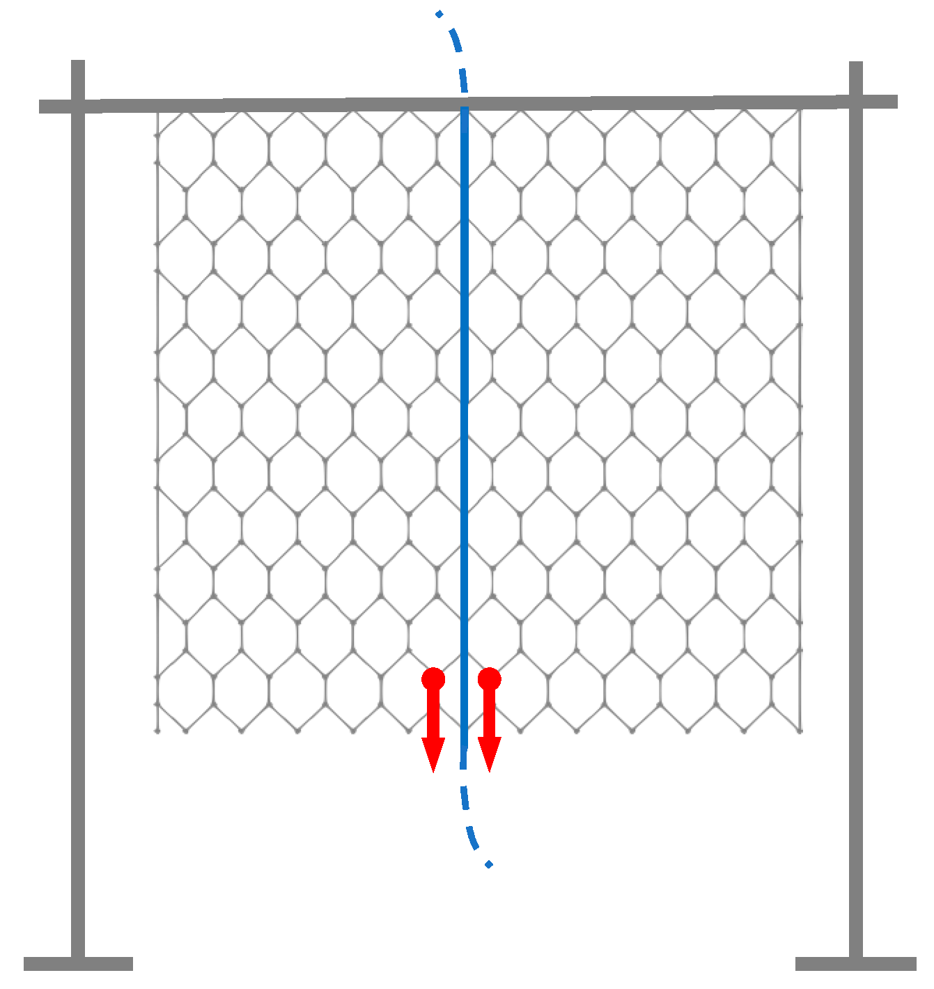
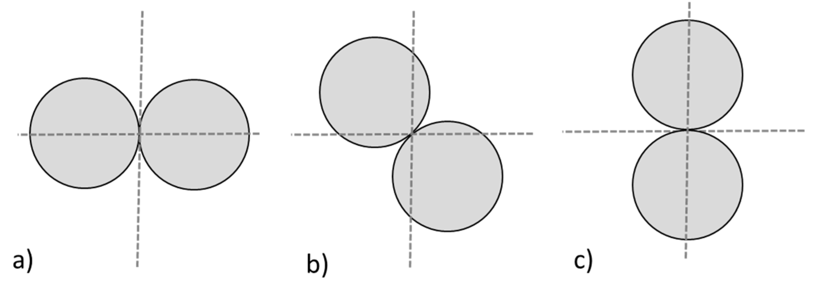
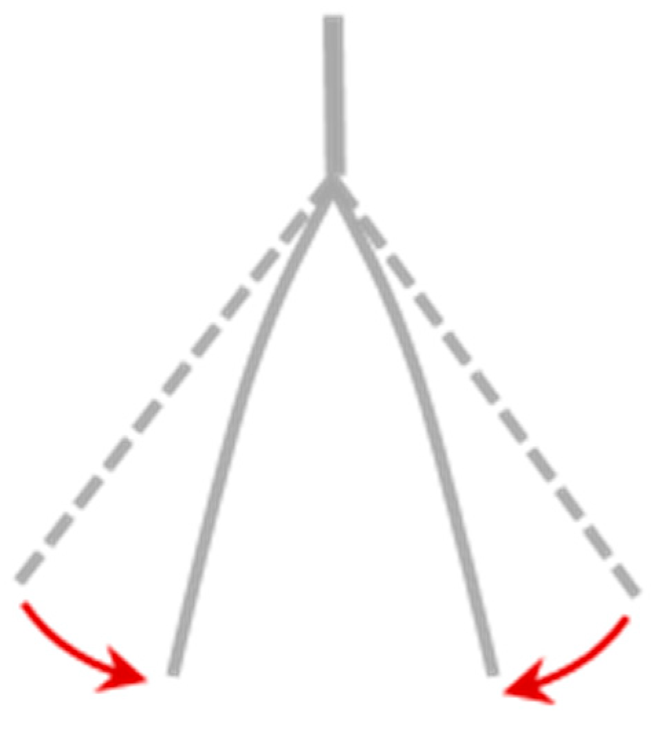
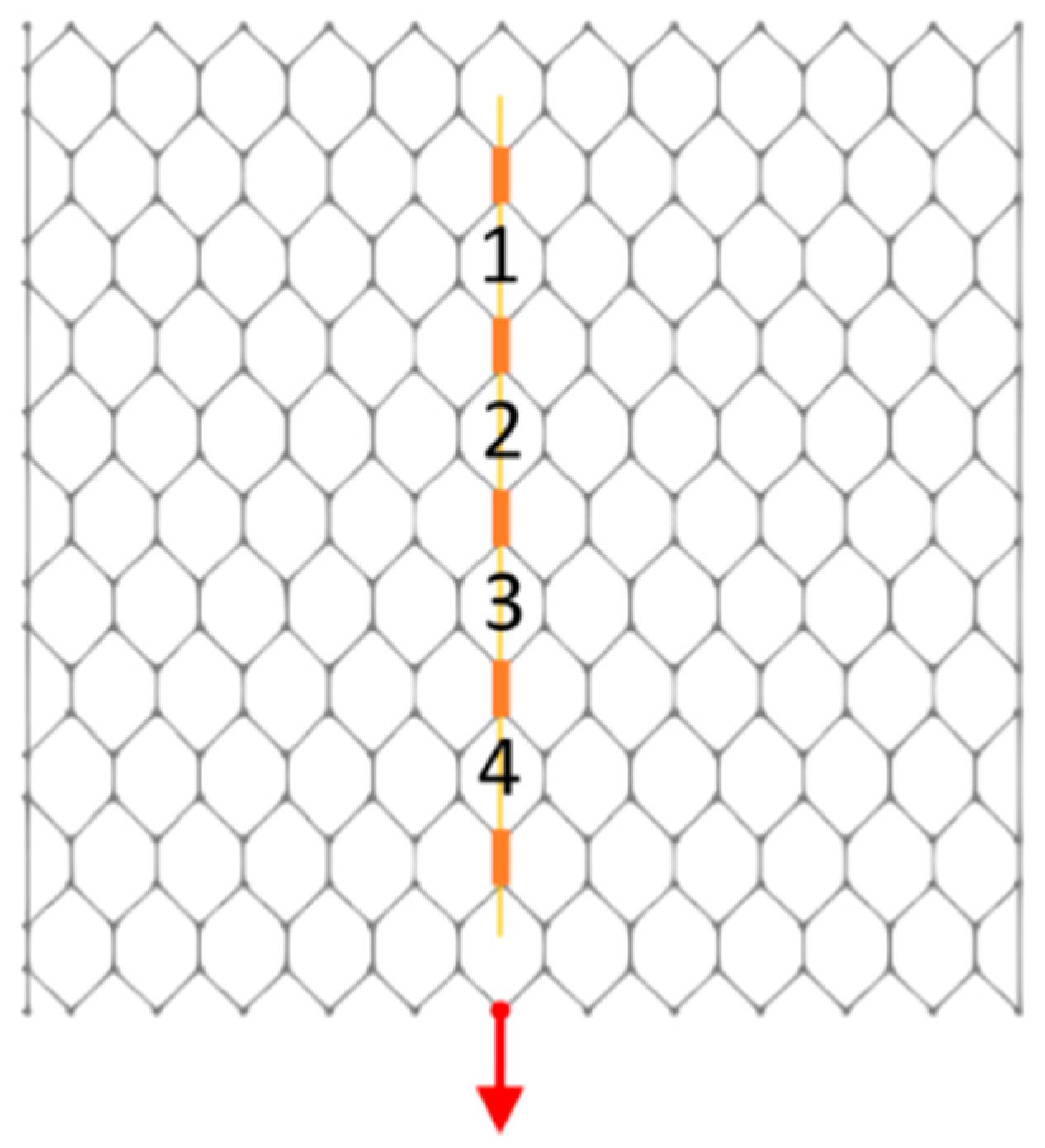
2.1. Stress Analysis

The dynamics of overflowing water on the top and on the outward face of an embankment have been widely studied in literature in the past [18,19,20]. Moreover, a complete and detailed numerical and experimental analysis of the fluid dynamic process of wave overtopping flow at seadikes is reported in [21], and a complete review is presented in a recent book [22].
The present work considers the case of the beginning of the overtopping flow in a riverine internal environment. The fluid exerts a shear stress on the levee surface given by:
τ o = γ S h
where τ o is the bed shear stress (N m−2), γ the specific weight of the fluid (N m−3), S the friction slope (–), and h the water depth (m).
The overtopping flow occurs once the level in the river exceeds the embankment top plane. The flow over the top is initially subcritical and generally becomes supercritical after a short distance. The flow is then accelerated due to the action of gravity starting as a laminar boundary layer and becoming turbulent as soon as the Reynolds number exceeds the critical threshold. This fact is easily observed by the change in shape and color of the nappe with air entrainment due to fluctuating velocity components in a direction normal to the flow.
As the flow accelerates the shear stress also increases until resistance to flow (proportional to the square of flow velocity) balances the action of gravity. This of course happens if the slope is long enough. At this point the two-phase flow (a mixture of water and air) becomes uniform and a maximum value is reached in the bed shear stress that will not be exceeded until at the downstream end, where a hydraulic jump takes place due to the sudden change in slope. This specific flow pattern has been studied in the last century [23,24]. Both papers agree on a functional relationship that univocally links the slope angle and the average air concentration in the uniform flow. For usual embankments, the layout slope angle ranges between 25 and 35 degrees, corresponding to an air concentration ranging between 35% and 50%. The paper by Wood also proposes equations for velocity distribution and flow resistance; the latter in the following form:
f = 8 g sin θ d U 2 ϕ ( d k , c )
where f (–) is the usual Darcy-Weisbach friction factor, g (m s−2) is the acceleration due to gravity, θ (–) is the slope angle, U (m s−1) is the velocity of the uniform flow, d (m) is the two-phase flow depth, and ϕ is a function of relative roughness ( k (m) is the homogenous equivalent surface roughness) and equilibrium air concentration c (–). With this formula, applied to Straub and Anderson’s experimental results, the author showed that no significant influence of air entrapment on the friction factor was observed for air concentration lower than 30%. In the present case a maximum reduction in the friction factor can be expected at 30%. However, it should be noted that outward facing slopes are particularly moderate, closer to the lower extreme of the above discussed angle range, while highest values are usually experienced on the internal face. For this reason, the correction has been neglected in the present work.
To determine the order of magnitude of the average stress on the revetment, one may imagine the first stage of the overtopping, with a water head in the river d 0 in the following range:
d 0 = 0.05 ÷ 0.15   ( m ) .  
above the embankment top. In this case, assuming broad-crested weir behavior for the sake of simplicity, the discharge for levee unit length (m2 s−1) is given by the usual formula:
q = 0.385 2 g d 0 3/2   =   0.019 ÷ 0.034 ( m 2 s 1 )
By assuming a value of the homogenous equivalent roughness
k = 0.070   ( m )
suitable for this kind of revetment [25], a maximum value for the average shear stress is obtained:
τ o = 58 ÷ 156   ( N   m 2 )
This stress range has been implemented both in numerical models and in experiments to test the ability of the OF cable to measure such a relatively low stress on the mesh structure.

2.2. Methodological Objectives of the Work

The conceptualization of the anti-erosion sensing revetment requires the achievement of three fundamental goals for which the product will be designed and developed.
The first one is to verify the possibility of coupling the OF cable with the DTWM, accounting also for any possible issues related to the manufacturing process.
As concerns the wire mesh, a 0.08 × 0.10 m double-twisted hexagonal mesh with a 2.2 mm steel wire diameter has been selected for the realization of the sensorized net. This kind of material is commonly used as a revetment in earthen structures (often coupled with a three-dimensional matrix polymeric geomat) in order to prevent erosion phenomena caused by factors such as heavy rainfall, surface runoff, and burrowing animals’ activity.
OF technology allows instead a distributed strain and temperature sensing along a single cable, suitable for structural health monitoring of civil infrastructures and offering several advantages in terms of installation and logistic issues [26]. At least two fiber optics within the cable are required, one tight for the strain and the other caged in a loose tube in order to adjust strain results with temperature. To achieve a native sensing revetment, the OF cable must feature high resistance to survive the weaving industrial process and withstand rodent attacks and environmental agents, while at the same time it should guarantee a high strain sensitivity to detect the slightest levee movements. Moreover, from an industrialization perspective, the OF cost must ensure an affordable sensing revetment for in-field applications.
The BRUsens DSS 7.2mm V3 grip, produced by Solifos AG, is the market item that met most of the requirements listed. It is an OF cable with a diameter compliant with the weaving machine requirement, with a strength member made of 24 steel wires, and an enhanced grip outer jacket to ensure rodent and abrasion protection.
Concerning the interrogation system technology to be used together with the sensing revetment, this represents a further fundamental part of the proposed monitoring solution. Indeed, strain and temperature Brillouin-distributed monitoring provides unique performance in terms of distance, spatial resolution, and accuracy. Most distributed systems rely on Brillouin Optical Time-Domain Analysis (BOTDA) techniques, based on pulsed optical pump signals which guarantee spatial resolution generally limited to one meter [27]. An alternative approach is Brillouin Optical Correlation-Domain Analysis (BOCDA), based on the simultaneous phase modulation of both pump and probe waves [28]. By following this approach, efficient amplification occurs only in a confined fiber section, called a “correlation peak” where the Brillouin phase-matching condition is fully satisfied. The correlation peak width can be made as narrow as needed and its position along the sensing fiber can be set by properly tuning the phase modulation rate. BOCDA sensors can thus guarantee high flexibility in measurement configuration with spatial resolution that can reach even a sub-centimetric scale, making it particularly suitable for preliminary laboratory diagnostic tests on scaled structures [29].
As shown in the previous section, the absolute value of shear stress due to water flow is relatively low compared to the one leading to yield stress in the steel wire. The OF sensor challenge, in this case, is not to be able to monitor deformations close to breaking in the material (as happens, e.g., in mesh punch tests) but, on the contrary, to detect minimal deformations such those caused by the onset of the overflow on the embankment.
In order to allow the sensorized net to correctly transmit the deformations to the OF, the double twisting process must be strong enough to tightly anchor the cable to the net twisted steel wires. On the other hand, this implies the use of steel armored OF cables to protect the sensor during the production process, that might make the fiber less sensitive to the deformations induced on the net.
Therefore, the second aim of this work is to study the mechanical behavior of the mesh stressed in its plane in order to understand the behavior of coupled DTWM-optical fiber system, the internal interactions between the two components, and the strain sensibility required by the interrogation system to monitor strain in the design range. Several works concerning wire mesh modeling can be found in the scientific literature, but they almost all deal with rockfall net systems [30]. As concerns numerical models, two main categories can be distinguished: Finite Element Method (FEM) or Discrete Element Method (DEM) models.
In FEM models, the DTWM is discretized in a mesh of interconnected finite elements which can be monodimensional (truss or beam elements), shell finite elements or special purpose elements [31]. This numerical method is suited for non-linear geometries and complex mechanical behaviors.
DEM models represent a good alternative when the wire mesh failure has to be considered. In this case the material is described by a series of rigid particles which can overlap during collision. The hexagonal double-twisted wire mesh is represented by a discrete number of spherical particles, placed at the physical nodes of the mesh. Remote interaction laws are then implemented to represent connections that join the particles [32].
In the present work a micromechanical numerical model of the wire mesh by using FEM has been implemented. Our research on shear stress effects along the mesh plane is actually quite different from that on rockfall barriers where (i) the entity of the actions exerted on the wire mesh are definitely higher and close (or even greater than) to wire yield stress; (ii) the out of plane displacement component of the mesh nodes (negligible in our case) is the main research target; (iii) the high value of stresses and deformations does not require us to consider the contribution of the bending stiffness of the steel wire that, on the contrary, is studied in the present case.
As far as the mesh is used as an erosion control mat against shear flow, the problem becomes quite complex. The shear stress exerted by the overflowing stream is adsorbed by the continuous grass turf which, through its root apparatus, transmits it to the sensing revetment due to the polymeric mat to which both the roots and the steel mesh are firmly anchored. This transfer mechanism is quite complex and requires specific laboratory and in situ studies in order to determine the effective stress range on the mesh. Experimental studies have been performed in the last century, e.g., at Colorado state University [33] in order to assess critical shear stress of DTWM in structures against erosion, particularly for mattresses. These are specifically empirical approaches in order to assess a critical value for velocity or shear stresses, mainly for design purposes. Our approach, on the contrary, is mainly focused on understanding the behavior of the smart DTWM in order to assess its effective sensing capability and its production by an industrial weaving machine. However, this transfer mechanism is surely a task for further development.
Finally, the third goal of the work is the development of a digital twin (i.e., a structural numerical model) of the sensing revetment. The availability of such a tool is in fact strategic because it can support and improve the technological validation and the subsequent design phase of the final product: known the acting forces and the constraints applied to the revetment, the model returns the expected deformations of the system, allowing us to understand which phenomena and which extent of displacements can actually be detected by the sensing OF.

2.3. Experimental Tests

The performed experimental activity consists of two distinct sessions in which OF cable sensitivity in detecting the deformation behavior of the wire mesh has been tested. The activity was performed at “POLICOM” and “Gaudenzio Fantoli” laboratories of the Politecnico di Milano. In both sessions and for each load applied the resulting longitudinal mean deformation of each sensorized mesh was measured.
During the first experimental session a standard telecommunication cable (SMF-28, coating 250 μm) was used to detect the mesh deformation and collect a first dataset for the calibration of the numerical model. The OF cable was glued at the double-twisted sections with an epoxy resin. The experimental setup adopted is sketched in Figure 3: a DTWM 8 × 10 cm 2.7 mm wire diameter square sample, one meter on each side, was bonded along its upper edge to a frame by means of cable ties. The OF cable installed was positioned as the blue line in the scheme: only the central four meshes have been sensorized. In-plane forces are applied through loads of a known mass hooked at the lower edge of the sample, as shown by the red arrow. Some details of the experimental setup are shown in Figure 4.
This setup remained substantially unchanged even during the second experimental session, where a first prototype of the sensing revetment was tested. The OF cable selected was integrated during the weaving process along the entire length of the DTWM sample. Hence, a total of eight meshes were sensorized. The weaving process required in this case a smaller wire diameter to work correctly: a DTWM 8 × 10 cm with a 2.2 mm diameter was used. Loads were equally distributed on two nodes at the same distance from the cable (Figure 5), in order to solicit more uniformly the OF cable.

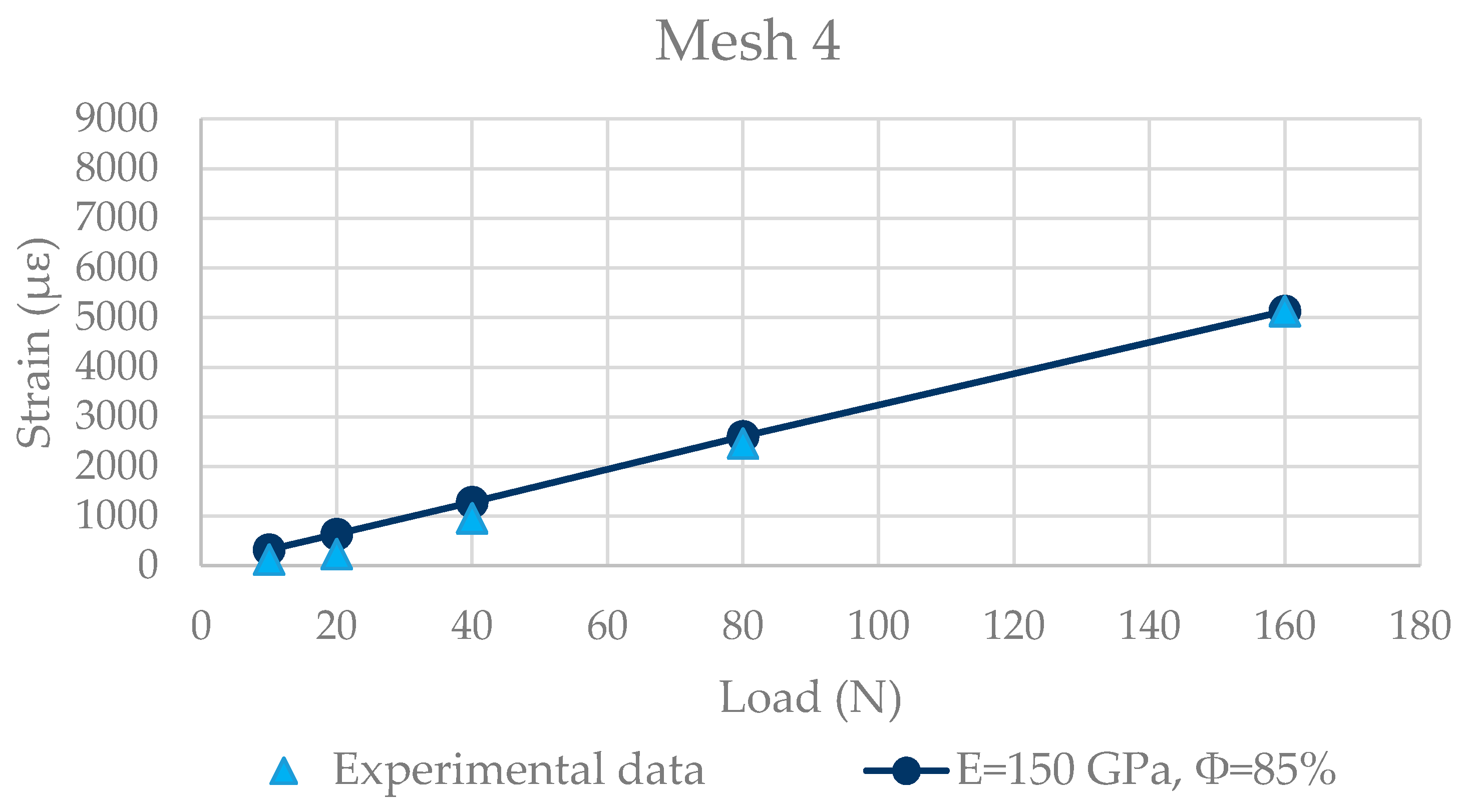
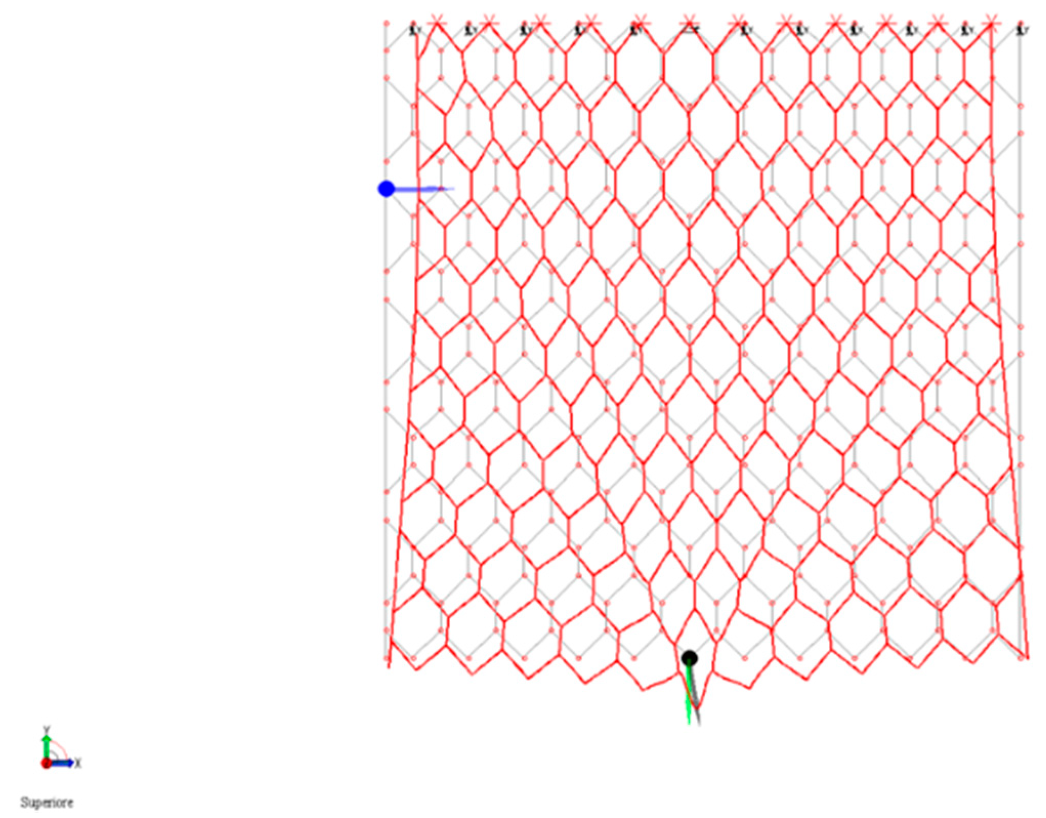
2.4. Numerical Model
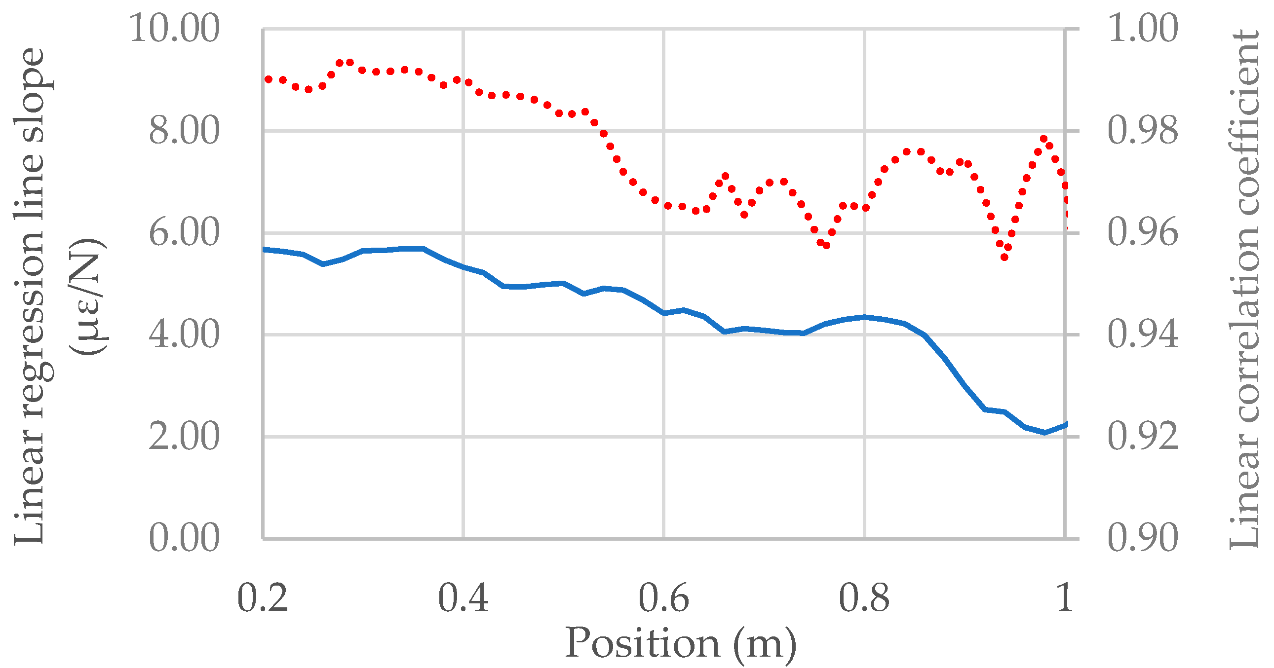
The model was implemented using the FEM software MasterSap, provided by AMV s.r.l., an Italian software house. The characteristics and the geometry of DTWM samples used during experimental activity have been accurately simulated in the model. In this regard, the non-perfect planarity of the wire mesh sample, which is inherent to this kind of revetment due to the typical production process and storage conditions, has been studied. This aspect was considered in the model by giving an out of plane coordinate to the mesh nodes following the usual sample curvature and considering geometric non-linearities. Furthermore, the wire mesh sample, once tied to the testing frame and subject to several load cycles, tends to gradually stretch, changing its out of plane shape. This problem is inherent to the specific type of material and recurs regularly during installation in the field. It was overcome during modeling by approximating the out of plane configuration via parametric sinusoidal and parabolic functions. The results were then compared with the 2D model, i.e., considering the wire mesh perfectly planar, in order to obtain a more general solution.
Each element of the wire mesh is represented by beam finite elements, according to the 2-node Euler-Bernoulli scheme, that is, one-dimensional elements capable of transmitting axial actions, cutting, and bending moments. Due to the relatively high slenderness of the elements, the shear deformability of the elements was not considered. According to the varying transversal characteristic sections of the different parts that form the mesh, three groups of circular section beam elements have been created: single wire elements, edge wire elements, and double-twisted wire elements. As regards the latter group, it is important to observe that the two wires that make up the double-twisted section change their relative position along the element axis (Figure 6) and, consequently, the moment of inertia of the two wires also varies.
Hence, for the sake of simplicity, a diameter able to produce the average value of momentum among the possible configurations was assigned to this group of elements.
The material assigned to each element has an elastic-linear behavior, and the mechanical parameters are those typical of steel: E = 150 GPa, υ = 0.3. Young’s modulus was calibrated using the results obtained from the first experimental session.
Once the steel wire parameters have been defined, a focus on the modeling of the mechanical behavior of the meshes as a whole was performed. As already stated, when a load is applied in the net plane, the mesh reacts by closing its geometry (Figure 7); this mechanism is achieved by two different actions: (i) reduction of the mesh opening, equal to 90° at rest, due to the presence of a mutual interlocking constraint with finite stiffness; (ii) flexural deformation of the wires by the residual transmitted moment.
A specific calibration of the rotational stiffness assigned to the meshes nodes was performed by progressively reducing the degree of connection Φ of the elements at the nodes of the meshes, starting from the perfect connection ( Φ = 100 % ). In the element definition, the degree of connection and the degree of stiffness are linked by the following formula
η = K a K g + K a = 1 ϕ
where K g is the joint stiffness and K a is the beam stiffness, both expressed in (N/m).
The implementation of the numerical model is completed with the definition of the boundary and load conditions compliant with those adopted during experimental tests, i.e., the sample fixed to a frame along the upper edge using nylon cable ties. This condition was modeled by using carriage constraints along the upper edge of the mesh sample. Moreover, a hinge constraint was applied to the central node of this edge, in order to avoid model lability in the mesh plane. Carriage constraints also have a constant stiffness along the vertical direction so as to simulate the elastic behavior of the nylon ties. Load conditions are applied according to experimental tests.
Finally, the OF cable was represented with beam elements having a circular section, a diameter equal to 7.2 mm and an elastic modulus obtained from tensile tests performed in laboratory. The double twisted sections in which the OF cable is inserted have been modeled considering the two wires twisted and the cable as three beam elements working in parallel.

3. Results

Calibration of steel wire Young’s modulus E and the connection degree Φ of the elements to the nodes was performed comparing observed and simulated deformations at the mesh vertexes (Figure 8).
The model returns the nodal displacements, and the OF elongation Δ l can be computed as follows:
Δ l = Δ x 2 + Δ y 2
where ∆x and ∆y are the respective differences in the translations of the nodes in the x and y directions, i.e., the two axes that in the model lie in the net plane when the load is applied. Then, it is possible to obtain the deformation of the OF by dividing its elongation by the longitudinal length of the mesh at rest.
The wire mesh, both in the experimental test and numerical model, is stressed in its plane progressively with the loads reported in Table 1. This range has been selected in order to study the mechanical behavior of the wire mesh when it is subjected to low-entity actions, as happens with an incipient overflowing stream.
In this step, as regards the numerical model, a planar geometry of the DTWM and a linear solution were considered. As far as Young’s modulus is concerned, the calibration process returns the best value that corresponds to the lower edge of the variability range indicated by the producer, 150 GPa. For the connection degree instead, the value that minimizes the difference between experimental and numerical values in the total dataset is chosen. This value is finally equal to 85%. The result obtained for mesh 4 is plotted in Figure 9. The blue line connects the numerical results, while the experimental ones are represented by the light blue triangles.
Looking at the graph, it can be seen that the linear model fits the experimental data quite well: the mean difference between experimental and numerical results is equal to 215 με. The fitting with experimental data remains good even in mesh 3 and mesh 2, whereas in mesh 1 the numerical solution underestimates the experimental one. This could be explained by the fact that mesh 1 is the nearest to the boundary conditions of the model and so it could be influenced by them due to the small dimensions of the sample. Another possible explanation can be found as an effect of the geometric non-linearities. As mentioned, in experimental reality the wire mesh sample is not perfectly planar. When a load is applied to the wire mesh, this tends to stretch, causing non-negligible out of plane displacements that can be taken into consideration by activating geometric non-linearities. Therefore, this hypothesis was investigated by changing from a 2D to a 3D model. The results obtained showed a slight improvement of the fitting as concerns mesh 1 with respect the 2D solution. However, at the same time, the fitting with experimental data worsened for mesh 4.
Once the calibration process was concluded, the numerical model was used to study the internal actions that arise in the DTWM when it is solicited in its plane. Indeed, for the conceptualization of the sensing revetment it is important to understand the mechanical behavior of the wire mesh, i.e., how the load propagates in the meshes and if the material remains, for the load range considered, within the elastic domain. Figure 10 shows the deformed configuration of the wire mesh when a concentrated load is applied at the lower edge of the sample, as done during experimental tests. Carriage constraints allow the horizontal shift of the lateral edges towards the central part, whereas at the same time the wire mesh stretches in its plane non uniformly.
The load, from the application point, migrates, determining a V-shaped area, inside which the meshes close their geometry. This migration path is also confirmed by the distribution of the internal actions given by the model, in particular axial action and bending moments. Analyzing the entity of these actions, it has been observed that within the tested load range all the elements are below the material yielding point.
During the second experimental session, as already mentioned, the OF cable was integrated for the first time in the DTWM. The cable has a non-negligible stiffness with respect to that of the wire mesh sample and so it has been adequately simulated even in the numerical model. During tests, the load set reported in Table 2 was applied to the DTWM, following the setup previously illustrated.
During the test, the OF cable detected the mean deformation with a sampling resolution of 2 cm. Therefore, for each sampling position the slope of the linear regression line and the correlation coefficient of the relation between the load applied and the resulting deformation were calculated. Figure 11 shows the trend of the two variables along the cable.
The results indicate that the OF cable, and therefore the wire mesh, deforms linearly: the correlation coefficient varies between 0.95 and 0.99. This confirms the results achieved at the end of the calibration process: the wire mesh, if solicited in its plane, maintains a linear deformation behavior even with the OF cable integrated.
Promising results are also obtained from the comparison with the numerical solution: always considering a planar geometry and a linear solution, the fitting confirmed the modeling hypothesis assumed both for the wire mesh and the OF cable.
As concerns the performance of the OF cable selected, measurements showed a halving of the strain sensitivity coefficient with respect to the bare fiber case. This reduction could be expected due to the presence of several layers in the OF cable. Nevertheless, the resulting sensitivity proved to be adequate to detect the DTWM deformation in the range tested. Further measurements are still ongoing in order to verify the presence of a possible relative sliding between the OF and the outer coating and to then quantify the exact strain transfer of the OF cable.

4. Discussion

The problem of levee embankment control during high flows is crucial for flood risk reduction in floodplains. Levee defense lines are often hundreds of kilometers long and surveys during an emergency are not an easy task. The concept of a smart levee is gaining increasing attention in the literature as a tool to help monitor and increase safety against floods.
The paper presents the conceptualization and the testing of a prototype of a levee smart revetment based upon the technology of a reinforced geomat obtained by a polymer made of a three-dimensional matrix extruded onto a double twisted steel mesh. The first applied use of this innovative technology patented by Officine Maccaferri allowed an OF cable to be embedded in a double twisted steel wire mesh, thus obtaining a continuous strain sensor along the revetment with a given space step.
In this paper the feasibility of this kind of a smart revetment is first assessed. A sample case is then analyzed in both numerical and laboratory tests. For this purpose, an FEM numerical model to describe the mechanical behavior of DTWM when loaded along its own plane is presented. The flow pattern of overtopping water on the embankment is also discussed, thus producing a raw estimation of the shear stress on the revetment. The result of the numerical model of the mesh indicates that the related strain, relatively low as compared to the steel wire yield stress, can be fully detected by the optical fiber continuous Brillouin sensor.
Laboratory tests confirm these results: the smart revetment is able to detect the strain of the same order of magnitude of that produced by water flow on the outer embankment face. In principle, this allows long embankment line reaches to be monitored for overtopping. Furthermore, the results allow us to presume that any significant deformation of the embankment surface (due, e.g., to a landslide) can also be detected by the optical fiber sensor.
Important outcomes are also achieved as concerns the study of the deformational behavior of the wire mesh: if the DTWM is solicited in its plane with the load range adopted, its meshes deform almost linearly. This behavior has been correctly simulated in the FEM model implemented, even considering a planar geometry of the DTWM sample. From the modeling activity the “digital twin” of the prototype of the smart material conceived has been obtained. This is a strategic tool that will be used to adequately test and design the revetment.
Furthermore, it should also be noted that the revetment itself acts as an excellent erosion control device, and the DTWM preserves the embankment against the action of rodents. Regarding this, it is important to note that the OF cable protection against crushing during manufacturing allows an equally good defense of the fiber core against the action of burrowing animals. Nevertheless, this aspect could reduce the strain sensitivity of the cable without affecting the correct detection of the in-field strain range for which the revetment has been conceived.
Next steps of the work will include, firstly, tests of planar multi-load actions (perhaps including terrain friction actions), as a simulation step under field operational conditions in order to provide a first relevant demonstration of the possibilities of the technology, and subsequently, a deployment of a prototype along a selected watercourse will be scheduled.

Author Contributions

Conceptualization, M.B., I.B., G.M. and F.Z.; methodology, M.B., A.C. and G.M.; investigation, M.B., I.B., M.F, J.M., F.Z.; validation, M.B., I.B., A.C., M.F., G.M., J.M. and F.Z.; writing-original draft preparation, M.B., G.M., M.F.; writing-review and editing, G.M., M.F. and D.F.B.; supervision, G.M., N.M. and D.F.B.; project administration, D.F.B.; funding acquisition, G.M. and D.F.B.; N.M., representing Maccaferri Innovation Center srl (employed by this company), contributed to the research, supervising the activities and manufacturing the tested prototype products. A patent on the tested products has been granted (patent applicant: Officine Maccaferri Spa; name of inventor: Francesco Ferraiolo; application number: IT 102018000004022-28.03.2018; status of application: patent granted; specific aspects of manuscripts covered in the patent application: tested samples and their components). Officine Maccaferri Spa is the sole controlling company of Maccaferri Innovation Center srl. All authors have read and agreed to the published version of the manuscript.

Funding

This research was partially funded by Maccaferri Innovation Center Srl.

Acknowledgments

The authors would like to thank Maccaferri Innovation Center Srl for supporting this research activity.

Conflicts of Interest

The authors declare no conflict of interest.

References

  1. EUCOLD Working Group on Levees and Flood Defences. European and US Levees and Flood Defences Characteristics, Risks and Governance; EUCOLD Working Group on Levees and Flood Defences. 2018. Available online: https://www.google.com.hk/url?sa=t&rct=j&q=&esrc=s&source=web&cd=&ved=2ahUKEwj5sLu45NbsAhXTLqYKHensDT0QFjAAegQIAxAC&url=http%3A%2F%2Fwww.barrages-cfbr.eu%2FIMG%2Fpdf%2Flfd_inventory_of_characteristics_risks_and_governance_full_report_final_20190308.pdf&usg=AOvVaw0Ked-2PgRoMFse9JuzofhN (accessed on 28 October 2020).
  2. Hughes, S.A.; Nadal, N.C. Laboratory study of combined wave overtopping and storm surge overflow of a levee. Coast. Eng. 2009, 56, 244–259. [Google Scholar] [CrossRef]
  3. Orlandini, S.; Moretti, G.; Albertson, J.D. Evidence of an emerging levee failure mechanism causing disastrous floods in Italy. Water Resour. Res. 2015, 51, 7995–8011. [Google Scholar] [CrossRef] [Green Version]
  4. Abbott, E.B. Review of disaster: Hurricane Katrina and the failure of homeland security. J. Homel. Secur. Emerg. Manag. 2007, 4. [Google Scholar] [CrossRef]
  5. Onuma, A.; Tsuge, T. Comparing green infrastructure as ecosystem-based disaster risk reduction with gray infrastructure in terms of costs and benefits under uncertainty: A theoretical approach. Int. J. Disaster Risk Reduct. 2018, 32, 22–28. [Google Scholar] [CrossRef]
  6. Tung, Y.K.; Mays, L.W. Risk models for flood levee design. Water Resour. Res. 1981, 17, 833–841. [Google Scholar] [CrossRef]
  7. Montz, B.E.; Tobin, G.A. Livin’large with levees: Lessons learned and lost. Nat. Hazards Rev. 2008, 9, 150–157. [Google Scholar] [CrossRef]
  8. Ojha, C.S.P.; Singh, V.P.; Adrian, D.D. Determination of critical head in soil piping. J. Hydraul. Eng. 2003, 129, 511–518. [Google Scholar] [CrossRef]
  9. Briaud, J.-L.; Chen, H.-C.; Govindasamy, A.V.; Storesund, R. Levee erosion by overtopping in New Orleans during the Katrina Hurricane. J. Geotech. Geoenviron. Eng. 2008, 134, 618–632. [Google Scholar] [CrossRef]
  10. Harteveld, C.; Guimarães, R.; Mayer, I.S.; Bidarra, R. Balancing play, meaning and reality: The design philosophy of levee patroller. Simul. Gaming 2010, 41, 316–340. [Google Scholar] [CrossRef] [Green Version]
  11. Hopman, V.; Kruiver, P.; Koelewijn, A.; Peters, T. How to create a smart levee. In Proceedings of the 8th International Symposium on Field Measurements in GeoMechanics, Berlin, Germany, 12–16 September 2011; pp. 12–16. [Google Scholar]
  12. de Vries, G.; Koelewijn, A.R.; Hopman, V.I. Jkdijk Full Scale Underseepage Erosion (Piping) Test: Evaluation of Innovative Sensor Technology. Scour Eros. 2010, 649–657. [Google Scholar] [CrossRef]
  13. Sekuła, K.; Borecka, A.; Kessler, D.; Majerski, P. Smart levee in Poland. Full-scale monitoring experimental study of levees by different methods. Comput. Sci. 2017, 18. [Google Scholar] [CrossRef]
  14. Bertulessi, M.; Bianchini, P.; Boschini, I.; Chiarini, A.; Ferrario, M.; Mazzon, N.; Menduni, G.; Morosi, J.; Zambrini, F. Conceptualization of an anti-erosion sensing revetment for levee monitoring: Experimental tests and numerical modelling. EGU General Assembly Conference Abstracts. 2020. Available online: https://ui.adsabs.harvard.edu/abs/2020EGUGA..2222495B/abstract (accessed on 28 October 2020).
  15. Li, H.-N.; Ren, L.; Jia, Z.-G.; Yi, T.-H.; Li, D.-S. State-of-the-art in structural health monitoring of large and complex civil infrastructures. J. Civ. Struct. Health Monit. 2016, 6, 3–16. [Google Scholar] [CrossRef]
  16. Horizon 2020—Work Programme 2014–2015, General Annexes. Technology Readiness Levels (TRL), Extract from Part 19—Commission Decision C. 2014, p. 4995. Available online: https://www.google.com.hk/url?sa=t&rct=j&q=&esrc=s&source=web&cd=&ved=2ahUKEwi33_Oq5dbsAhWCNaYKHf7vAtMQFjAAegQIARAC&url=http%3A%2F%2Fec.europa.eu%2Fresearch%2Fhorizon2020%2Fpdf%2Fwork-programmes%2Fgeneral_annexes_draft_work_programme.pdf&usg=AOvVaw085cfUj4JAeagGVm1RIJ5V (accessed on 28 October 2020).
  17. Serafinska, A.; Özenç, K.; Kaliske, M. A coupled approach of optimization, uncertainty analysis and configurational mechanics for a fail-safe design of structures. Int. J. Numer. Methods Eng. 2017, 109, 125–152. [Google Scholar] [CrossRef]
  18. Ralston, D.C. Mechanics of Embankment Erosion During Overflow. In Hydraulic Engineering; ASCE: Reston, VA, USA, 1987; pp. 733–738. [Google Scholar]
  19. Powledge, G.R.; Ralston, D.C.; Miller, P.; Chen, Y.H.; Clopper, P.E.; Temple, D.M. Mechanics of overflow erosion on embankments. II: Hydraulic and design considerations. J. Hydraul. Eng. 1989, 115, 1056–1075. [Google Scholar]
  20. Hanson, G.J.; Cook, K.R.; Hunt, S.L. Physical modeling of overtopping erosion and breach formation of cohesive embankments. Trans. ASAE 2005, 48, 1783–1794. [Google Scholar] [CrossRef]
  21. Schuttrumpf, H.; Oumeraci, H. Layer thicknesses and velocities of wave overtopping flow at seadikes. Coast. Eng. 2005, 52, 473–495. [Google Scholar] [CrossRef]
  22. Li, L.; Amini, F.; Pan, Y.; Yuan, S.; Cetin, B. Hydraulics of Levee Overtopping; CRC Press: Boca Raton, FL, USA, 2020. [Google Scholar]
  23. Straub, L.G.; Anderson, A.G. Experiments on self-aerated flow in open channels. J. Hydraul. Div. 1958, 84, 1–35. [Google Scholar]
  24. Wood, I.R. Uniform region of self-aerated flow. J. Hydraul. Eng. 1983, 109, 447–461. [Google Scholar] [CrossRef]
  25. Agostini, R.; Conte, A.; Malaguti, G.; Papetti, A. Flexible Linings in Reno Mattress and Gabions for Canals and Canalized Water Courses; Maccaferri Main Head Office: Bologna, ltaly, 1985. [Google Scholar]
  26. Ye, X.W.; Su, Y.H.; Han, J.P. Structural health monitoring of civil infrastructure using optical fiber sensing technology: A comprehensive review. Sci. World J. 2014, 2014. [Google Scholar] [CrossRef] [PubMed] [Green Version]
  27. Motil, A.; Bergman, A.; Tur, M. State of the art of Brillouin fiber-optic distributed sensing. Opt. Laser Technol. 2016, 78, 81–103. [Google Scholar] [CrossRef]
  28. Zadok, A.; Antman, Y.; Primerov, N.; Denisov, A.; Sancho, J.; Thevenaz, L. Random-access distributed fiber sensing. Laser Photonics Rev. 2012, 6, L1–L5. [Google Scholar] [CrossRef]
  29. Morosi, J.; Ferrario, M.; Boffi, P.; Martinelli, M. Double slope-assisted Brillouin optical correlation domain analysis. In Proceedings of the 2017 Conference on Lasers and Electro-Optics Europe & European Quantum Electronics Conference (CLEO/Europe-EQEC), Munich, Germany, 25–29 June 2017. [Google Scholar]
  30. Bertrand, D.; Nicot, F.; Gotteland, P.; Lambert, S. Discrete element method (DEM) numerical modeling of double-twisted hexagonal mesh. Can. Geotech. J. 2008, 45, 1104–1117. [Google Scholar] [CrossRef]
  31. Thoeni, K.; Lambert, C.; Giacomini, A.; Sloan, S.W. Discrete modelling of hexagonal wire meshes with a stochastically distorted contact model. Comput. Geotech. 2013, 49, 158–169. [Google Scholar] [CrossRef]
  32. Pol, A.; Gabrieli, F.; Thoeni, K.; Mazzon, N.; Corominas, J.; Moya, J.; Janeras, M. Discrete element modelling of punch tests with a double-twist hexagonal wire mesh. In Proceedings of the 6th Interdisciplinary Workshop on Rockfall Protection, Barcelona, Spain, 22–24 May 2017. [Google Scholar]
  33. Simons, D.B.; Chen, Y.H.; Swnson, L.J. Hydraulic Test to Develop Design Criteria for the Use of Reno Mattresses. In Report for Maccaferri (1984); Colorado State University: Fort Collins, CO, USA, 1984. [Google Scholar]
Figure 1. Detail of OF cable woven into the wire mesh: the cable is directly inserted into double-twisted sections during the weaving process.
Water 12 03025 g001
Figure 2. Sketch of the working principle of the sensing revetment: the OF cable (blue line) detects the closure of the meshes by deforming itself.
Water 12 03025 g002
Figure 3. Experimental test setup—first session: the OF cable is glued at double-twisted sections.
Water 12 03025 g003
Figure 4. Details of the experimental setup: (a) OF glued at the double-twisted sections; (b) constraints applied to the DTWM.
Water 12 03025 g004
Figure 5. Experimental test setup—second session: the OF cable is integrated in the DTWM.
Water 12 03025 g005
Figure 6. The moment of inertia of the twisted wires change according to their relative position: considering the horizontal axis, the minimum value is obtained in (a), while the maximum one in (c). The configuration shown in (b) returns the average value.
Water 12 03025 g006
Figure 7. Sketch of the geometrical closure of the generic mesh when a load is applied in its plane; the closure is given both by a reduction of the vertices openings and the bending of the wires.
Water 12 03025 g007
Figure 8. Meshes sensorized during the first experimental session. Each mesh has been labelled with the number shown in the image.
Water 12 03025 g008
Figure 9. Experimental vs. numerical results—mesh 4.
Water 12 03025 g009
Figure 10. Amplified deformed configuration of the DTWM caused by the application of a concentrated load of 160 N.
Water 12 03025 g010
Figure 11. Linear regression slope and linear correlation coefficient obtained along the OF cable integrated in the DTWM.
Water 12 03025 g011
Table 1. Loads applied to the wire mesh both in experimental and numerical activity-first test sessions (standard gravity g assumed equal to 10 m/s2).
Loading StepLoad (N)
110
220
340
480
5160
Table 2. Loads applied to the wire mesh both in experimental and numerical activities—second test session (g assumed equal to 10 m/s2).
Loading StepLoad (N)
150
280
3100
4120
Publisher’s Note: MDPI stays neutral with regard to jurisdictional claims in published maps and institutional affiliations.

