

Introduction: Low Cost DIY CNC Router


UPDATE: What is good is getting better. Here's the next installment on this router: Click Here
_____________________
This is a hobby CNC router I built for myself that I'd thought I'd share with the Instructables community. This is not a detailed build log of the router but more of an exploration of my design choices that went into this somewhat unique tool. There are no plans for this router. Beyond a couple of initial sketches to determine general size, lengths, and spacing, this router pretty much grew out organically as I was building it. Hopefully other CNC enthusiasts may see an idea or two that might help them with their projects.
Design parameters
- Use as much stuff that I had laying around the shop as possible.
- Able to use the router as a bench top when not routing.
- A cutting area of 30"x60"x2".
- Make it as rigid as possible (for a plywood design).
As to the design I came up with. This is a classic XYZ 3-axis wood cutting router. By classic I mean it has a gantry that moves along the length of the machine base (Y axis). There is a carriage that the router is mounted to that runs back and forth on the gantry (X axis). And finally, there is a mechanism that raises and lowers the entire gantry that moves the router up and down (Z axis). Yes, I said the entire gantry moves up and down. We'll be getting into that later. As to motion, I'm using stepper motors and roller chain. For the linear rails, I'm using steel v-bearings running over steel angle iron. The primary construction material is plywood.
Lets get to the picture show.
Step 1: The Base


Every tool needs a good base. Instead of building from scratch I re-purposed an Ikea cabinet I had available. The cabinet was completely disassembled and then put back together using adhesive at every junction. I reinforced the cabinet by melding in a 2x6 substructure on the bottom. Casters and levelers where added for mobility. Finally, I used a commercial solid core door for a bench top. Not shown, but the door was shimmed so it would lay as flat and true as I could make it. The door will be the actual base for the router.
Why a solid core door for the machine base? For one, I had it available. I use these doors as bench tops in my shop. Secondly, commercial solid core doors are built to be as flat and true as possible. And third, their heavy as hell and I thought all that mass would be advantageous in soaking up vibrations from the router.
Step 2: Linear Rails


Linear rails for CNC seem to be a dime a dozen nowadays on eBay and Alibaba, but in 6' lengths? Not so cheap. What is cheap is 1" angle iron at my local home center. Something else that's cheap (at least cheaper than they used to be) are 3/8" ID steel v-bearings. Combine the two, and we get the linear rail system I'm using in this build. Pictured here are my first tests using angle iron and the v-bearings. Seemed to work well so I cut the 45 degree plywood rail beds on the tablesaw and mounted the angles to the underside of the router base. Not well pictured, but tensioning of the v-bearings onto the angle is accomplished by a bolt and dowel-nut setup. Those slits between the v-bearings allow for enough movement for the tensioning.
Something you may have noticed are the plywood strips attached to the edge of the door/router table. There's nothing significant about these. After I cut the door to size I decided I wanted to increase the X travel to a full 30" which required widening the table.
Why mount the Y rails under the table? This left the top clear so the entire surface could be used for cutting. It also allows me to use the router as a work/assembly bench when I'm not routing.
Notice how far apart the the pairs of Y axis v-bearings are apart on the bottom of the gantry side plate? I did this to mount the gantry plates as rigidly as possibly. This made the plates longer which required more table length to get me the 60" of Y travel that I wanted.
Sorry to say but this is about it for historical photos of this build. The pics that follow were all taken after the router was pretty much complete and operational.
Step 3: Gantry and Carriage Details


UPDATE: I've dumped the flying gantry design of this router. Moving the entire gantry up and down for the z-axis motion worked ok but it had issues. Mainly that it was very slow. It could also occasionally go out of alignment if one side skipped steps. The router has been rebuilt with a new setup where I moved the z-axis mechanics to a new router carriage. You can check that out at part two of this build series.
The gantry is built from two layers of 3/4" ply glued together. Along the top and bottom, 45 degree recesses were cut and 3/4" angle irons where bonded into them using Gorilla glue. The entire gantry moves up and down for the Z axis motions. To accomplish this, the gantry has a length of 1" angle iron in the vertical orientation that sit in v-bearings attached to the gantry side plates. The up and down power is supplied by a NEMA 23 stepper and screw assembly on each end.
Notice the gantry overhangs? The gantry beam is mounted in front of and extends past the side support plates. This allows the router carriage to slide past the side supports (more on the right than on the left btw). You don't see this much on DIY routers for some reason. This setup allows the router to cut from edge to edge a full 30" in the X axis.
The router carriage is glued up from two layers of 1/2" cabinet grade plywood, much the same way as the gantry side plates. Since I have that overhanging gantry, I was able to make the router carriage longer (spreading the v-bearings further apart) which increases rigidity in the X axis. The Makita router is mounted on the left side of the carriage. This opened up area for the dust collection system to the right of the router. The carriage has four of the v-bearings that run on the top and bottom angles on the gantry. Tensioning is done the same way as on the gantry side plates.
Flying gantry? To provide the Z axis motion the entire gantry moves up and down. On most CNC routers the gantry is fixed and the Z axis motion is all done at the router carriage. I'm moving the entire gantry for a few reasons. First, my thinking is that if I moved the Z axis mechanics out to the ends placing them between the gantry and the gantry side plates, I could spread the loads out and increase rigidity. Secondly, removing all the Z axis mechanics and motor from the router carriage, greatly simplified wiring going to the carriage. Third, I figured why not? It works in 3D printers and as it turns out, is working quite well with this router. Besides, it looks cool when the entire gantry moves up and down.
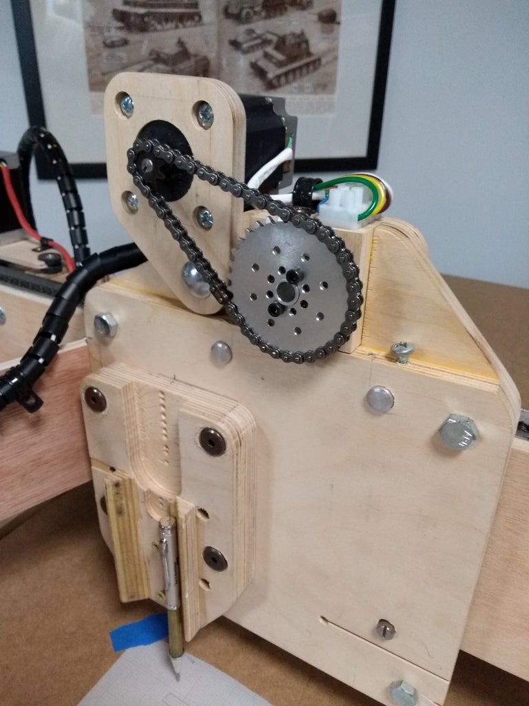
Z motor mounting. What may not be obvious is how I have the two Z motors attached and mounted to the jack screws. In a typical setup, these motors would be hard mounted to a base. The screws would be mounted in a bearing assembly. To connect the two would be a flexible coupling. I avoided all that complexity by hard mounting the motors to the screw shafts. The only thing holding those motors in place are the 1/4" shafts stuck into the 1/4" holes I drilled into the screw shaft ends on my mini-lathe. The motors are kept from spinning by the wood bracket with that rubber bushing on the end (which allows the motor to wobble if it has to). This may seem an odd way of doing this but this method eliminates the flexible coupling and fiddling with alignment. The 1/4" shafts of the stepper motors are more than strong enough to keep the motors in place.
For X and Y axis motion, the carriage has one NEMA 23 240oz (torque) stepper mounted. The Y axis motion is powered by a single 425oz stepper that is driving a shaft that is attached to both ends of the gantry. Mechanically, it would have been easier to go with two steppers for the Y axis but I only had one motor available at the time and I had the shafting and bearings to fabricate the drive. One nice thing with this setup is that the gantry will never go out of alignment due to a motor skipping.
A chain reduction on the axis drives? I first built this with the stepper's driving the chains directly. In the initial testing, I was getting a lot of skipping in the (weak) motors I was using at the time. I had the sprockets and bearings available so I added the reductions. Besides adding a ton or torque, they definitely helped in the precision category (more on that later).
Step 4: Roller Chain?


Yep, I used 25P roller chain in this build. I didn't use timing belts, ballscrews, or rack and pinion. If you don't know, roller chain has a bad rap in the DIY CNC community. Arguments against are that it stretches, it's not very accurate, and it caused the fall of the Roman Empire! Anyhow, I didn't know all that when I started this build and I had a bunch of the chain left over from another project. I'm enough of an engineer to know that roller chain could have issues but I had some ideas on how to mitigate those. Before I started this build I'd studied other chain driven designs and always noticed one thing. These other chain designs always seemed to have the chain hanging out in mid-air, unsupported, with some sort of flimsy looking tensioning system on the ends. Roller chain has some weight to it, even #25 chain. What will happen if 5' of it suspended horizontally in mid air? It will droop and no matter how tight you tension it, it will still droop to some degree. What that droop on a linear motion system means is that you will not get consistent movement along it's length. What I did with this design is that the chains are supported along their entire lengths. The X axis chain sits in the bottom of the top angle of the gantry. The Y axis chains lay in a cutout in the Y angle supports. There's no drooping in these chains! To secure the ends of the chains, I used 3mm hex wrenches which fit quite nicely in the #25 chain. Tensioning is handled by flexible sections of ply on one end of each of the chains. A tensioning screw runs though a t-nut which bends the ply tensionor out and pulling the chain taught.
Note that the chain mounting and tensionors sit right on the angle iron ends. This setup uses the angles in compression to add to the rigidity of the chain mounting.
What's that coupling looking thing in the first pic? That's a compression coupling that joins the left and right Y axis sprocket drives. Loosening this up allows me to precisely adjust the gantry perpendicular to the Y axis travel.
Step 5: Router and Dust Collection


The router is the Makita RT0701C 1/4" trim router (earlier pics show a cheap Harbor Freight router which has since been chucked). The router has turned out to be precise and it has a nice speed adjustment built into it.
Dust collection. I have a small basement shop and I wanted good dust collection on this machine. One wrinkle with this design is that since the router carriage moves up and down with the gantry, I had to come up with a design that keeps the dust shoe on the work piece. This was accomplished by mounting the dust shoe on an arm that allows it to freely move up and down in relation to the gantry. Three plastic v-bearings were used as shown in the pic. The one bearing is attached to the movable arm that allows for a quick and easy removal of the dust shoe from the machine. The dust shoe was machined (first thing I cut on this router) out of two pieces of 1/2" plywood. The bottom pad was cut out of a painting pad and allows the shoe to float over any screws or bumps in the work piece.
The dust cyclone is mounted on top of a standard 5 gallon bucket and keeps most (if not all) the dust out of the 8 gallon shopvac that I'm using.
This setup has proven very good at sucking the dust and chips up. After a cut, there's hardly any dust left on the work piece or floating around the shop.
Step 6: Controls and Wiring


Not many pics on this one I'm sorry to say. The control system is Arduino UNO based and I'm running the EstlCAM CNC software (which is awesome IMO). On the wall is a little Windows 10 media PC that is running the Windows side of the EstlCAM system. A wireless keyboard, mouse, and a game-pad finish the controls out.
On the back of the machine inside the black box in the center is an Arduino Uno which is running the Estlcam controller software. In the electrical box is a 10A SSR (solid state relay) which switches the router on and off. To the left on a shock mounted base are the TB6600 stepper drivers. The power supply is a 24V 15A fanless design.
No whirlygigs! I made an effort to use fanless passively cooled equipment for all my electronics. This is so no dust gets sucked into anyplace it shouldn't be. I also kept an eye on mounting orientation. The stepper drivers are mounted so heated air will naturally flow upward. The Arduino case has holes drilled into the top and bottom for the same reason.
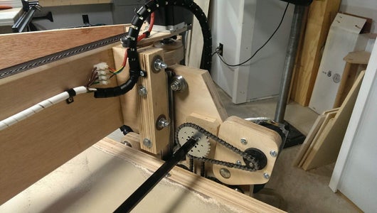
The wiring to the motors is running through the flexible black cable protectors picked up at a computer store. The motor cabling is four conductor trailer wire.
Noticed that articulated cable support going to the router carriage? A couple pieces of plywood and some hinges, and a quick and easy cabling solution to the carriage is the result. Works quite well.
Step 7: Does It Cut?


Of course it does!
There's been issues of course and It's a continuing learning curve. I've been experimenting with materials, cut depths, and feed rates to see what the router can do.
Currently, for cutting plywood and MDF, I've been running around 70IPM (inch per minute) speeds on a .25 bit with a .28 cut depth. The Z axis is currently set to 20IPM.
Free travel speed is set to 140IPM with no issues.
Step 8: Is It Accurate?


How's .005" repeat-ability sound? That's 0.127mm for you metric types. Yeah, I know. That sounds to good to be true with a DIY roller chain driven plywood router but that's what I've seen in some of my testing. I'm not saying .005" accuracy will come out of this machine with every cut but at even four times worse, it's a lot more accuracy than I was ever expecting.
So why so accurate? Who knows? Maybe I'm an uber machine designer and fabricator. Maybe that reduction on the motors had something to do with it? Maybe the stars were in alignment? All I know is I'm very happy with it. Not to shabby for a machine that might have $900 of material in it.
Hope you enjoyed this write up. I'll add content as I think of it and I look forward to any comments or suggestions.
Thanks for reading.
Steve
Step 9: Accesories
First thing you learn when you get your CNC router up and running, is that you immediately want to start improving it. My first project along these lines was a touchplate for automatic zeroing. These are usually made from milled aluminum but I figured some plywood and some aluminum tape and strips would work. It did!

Grand Prize in the
First Time Author Contest


