

Abstract
As a new generation of capacitors, lithium-ion capacitors (LICs) have the same power density and cycle life as traditional electric double-layer capacitors, and 2–5 times the energy density. For the first time, in this paper we derive the mathematical formulas for the energy density of LICs. These formulas describe the relationship between the energy density of LICs and all the critical parameters, including the specific capacities of anode (negative) and cathode (positive) electrodes, the capacity ratio of anode to cathode electrodes, the maximum and minimum voltages of the LICs, the specific capacity of pre-lithiation source and the degree of the pre-lithiation and so on. These formulas provide not only a clear direction for future research in materials and devices of LICs, but also a useful tool for LIC design.
Export citation and abstract BibTeX RIS
The electric double-layer capacitor (EDLC), commonly known supercapacitor or ultracapacitor, was first developed in 1957 by General Electric.
1
The most important advantages of a supercapacitor are its high power density (e.g. >10 kW kg−1) and an extremely long cycle life (e.g. >1,000,000 cycles). The capacitor consists of two symmetrical porous activted carbon elecrodes, with an electrolyte filling the pores in these electrodes.
2,3
Since all the charges are stored on the surface of the carbon, there is no charge transfer and no diffusion process inside carbon, therefore, the EDLCs have high power density and extremely long cycle life. However, its biggest disadvantage is that the energy density is an order of magnitude lower than that of lithium (Li)-ion batteries (LIBs).
3,4
In order to have the ability to store more charge, the electrode material must have a very high specific surface area; but it also brings three factors that are not favorable to energy density; (1) the high specific surface area results in high porosity of the electrode, which further causes more electrolyte adsorption in the electrode, limiting the capacitor's the energy density; (2) the high specific surface area also has a negative effect on the maximum operating voltage of the capacitor, which is determined by the electrochemical stability window, since the electrochemical side reactions are proportional to surface area; and (3) regardless of any improvement in the porosity and electrochemical stability of the electrodes, the energy density of the EDLCs will eventually be limited by the effective ion concentration of the electrolyte. This is because when an EDLC is fully charged, all the charges accumulated on the surface of the activated carbon come from the electrolyte.
5,6
The maximum cation or anion concentration in liquid electrolyte (e.g. 6.022 × 10²⁰ ions cm−3 for 1 M l−1 Et4NBF4 in acetonitrile,  ) is only about 2%-4% of that in solid battery electrode materials (e.g. 1.84 × 10²² Li atoms cm−3 for LiC6 and 3.0 × 10²² Li atoms cm−3 for LiCoO2).
Li-ion Capacitors
Recently, a new type of capacitor, Li-ion capacitor (LIC), has been developed which not only has all the advantages of the EDLC, including high power density and extremely long cycle life, but also has much higher energy density and lower self-discharge rate. 7–14 A LIC is composed of a pre-lithiated LIB (Faraday)-type anode (negative) electrode, an electric double-layer capacitor (EDLC) -type cathode (positive) electrode, and a Li-ion-containing electrolyte. The cathode material is activated carbon, and the anode materials include graphite, hard carbon, soft carbon, Li titanate, etc. In comparison with EDLCs and LIBs, in addition to the different characteristics in charge exchange, the LIC has two very distinct characteristics: (1) the capacity of anode is several times that of cathode (e.g. 7–10 × for hard carbon and 10–15 × for graphite as anode). 7,15 Due to the distinct energy storage mechanisms of cathode (non-Faradic) and anode (Faradic), the high-rate performance and cycling durability of anode are not comparable to that of cathode, which will result in low power density and poor cycling lifespan. A general method to improve the power density and cycling lifespan is to construct a capacity imbalanced system, i.e. designing a LIC that capacity of anode is greater than that of cathode, which enables the anode to be working at a low area current density and hence, experiencing a shallow charge and discharge, as shown in Fig. 1a that maqa ≫ mccc(Vc-max-Vc-min). The reduced area current density on anode makes it work well even at high cell current condition, improving the power density of LICs. 15,16 The shallow charge and discharge can reduce the volume change and lattice strain of anode, resulting in improved cycling durability; and (2) the anode electrode of LIC must first undergo a process of pre-doping Li, so called pre-lithiation, which serves at least two purposes: (1) to provide the Li source needed during the charging and discharging and for the initial capacity loss of the anode in order to reduce the consumption of Li ions in the electrolyte as much as possible; and (2) to allow the anode to work in an optimized potential region. 17–21 It should be pointed out that asymmetric electrochemical capacitors consist of a LIB-type electrode and an EDLC-type electrode have been demonstrated since 2001, 22–24 and a mathematical model was developed to describe the dynamic changes inside asymmetric electrochemical capacitors during charging and discharging. 25 ; however, the fundamental difference between previous asymmetric electrochemical capacitors and LICs discussed in this paper is that the pre-lithiation (or pre-doped ions) technology was not applied to asymmetric electrochemical capacitors; therefore, all ions came from the salts in the electrolytes and is an important limitation factor. The theoretical specific energy and energy density for such kind of asymmetric electrochemical capacitors can be found from Ref. 26.

Figure 1. Illustration of: (a) LIC structure before and after pre-lithiation; (b) electrode potentials after the pre-lithiation; and (c) electrode potentials and charge movement during the 1st cycle. mc and ma are weights of cathode and anode, respectively, cc is the specific capacitance of cathode, qa is the specific capacity of anode, Va is the potential of anode, Vc-PZC is the potential of zero charge of cathode, Vc-max and Vc-min are the maximum and minimum potentials of cathode, Vmax and Vmin are the maximum and minimum voltages of LIC, and δ is the degree of pre-lithiation of the anode. The solid line represents the capacity due to intercalation and dashed line represents the capacity due to ICL.
Download figure:
Standard image High-resolution imageFigure 1b illustrates possible profiles of anode and cathode potentials after pre-lithiation. The potential of zero charge of the LIC cell is dependent on potential difference between the cathode potential of zero charge (Vc-PZC) and anode potential after pre-lthiation. The maximum cell voltage is determined by the difference between maximum allowed potential of cathode and minimum allowed potential of anode. For example, the activated carbon can be cycled at potentials below 4.0 V vs Li/Li+ without significant degradation after hundreds of thousands of cycles. The anode is designed to be operated near or above 0.2 V vs Li/Li+ by controlling the degree of pre-lithiation. The purpose of avoiding the operation of the anode in a potential range < 0.2 V vs Li/Li+ is to ensure the high power characteristics of the LICs. Therefore, when the LIC is charged at high currents, the potential of the anode will not exceed values lower than the potential of Li and hence, no Li plating occurs. Combining the maximum allowed potential of cathode and minimum allowed potential of anode, the maximum cell voltage of LICs is 3.8 V. The minimum cell voltage is limited by the minimum allowed potential of cathode due to its extremely high specific surface area. It was found that when the potential of the activated carbon cathode is lower than 2.2 V vs Li/Li+, the cycle life of LICs reduces and internal resistance increases significantly due to solid electrolyte interface (SEI) layer growth on the surface of activated carbon. 27–29
The special structure of LIC determines that the charge exchange processes have both EDLC and LIB characteristics. Figure 1c shows the charge exchange processes of a LIC after pre-lithiation during the first cycle, 30 which can be divided into four ranges. (1) in range I, the LIC is charged and cathode potential is above the PZC, the cations of Li+ and anions of PF6 − insert into anode and adsorb on the cathode surface (to build a double-layer), respectively; therefore, the salt in the electrolyte is consumed during the charge process; (2) in range II, the LIC is discharged and cathode potential is above the PZC, the Li+ and PF6 − go back to electrolyte from bulk of anode and surface of cathode, respectively; (3) in range III, the LIC is discharged and cathode potential is below the PZC, the Li+ moves from bulk of anode to the surface of cathode, with no net charge exchange with electrolyte; and (4) in range IV, the LIC is charged and cathode potential is below the PZC, the Li+ moves back from the surface of cathode to bulk of anode.
As described above, the design of a LIC needs to consider not only the specific capacities, working potentials, cycle stability, etc. of the anode and cathode electrodes in conventional electrochemical energy storage devices, but also other important factors, such as pre-lithiation and the capacity ratio of anode to cathode, etc. Because of the relative complexity of LIC, calculating and predicting its specific energy or energy density cannot be as straightforward as EDLCs or batteries. This paper will derive mathematical formulas of the specific energy and energy density of LICs in detail, including the relationships of the specific energy and energy density to some special parameters, such as the pre-lithiation material and the capacity ratio of the anode to cathode.
For a practical LIC, the specific energy and energy density is determined by all components in the cell, including active anode and cathode materials, binder for electrode, electrolyte, separator paper, current collectors, electrical tabs and other package materials. Many parameters are needed to describe these components, such as specific capacities for anode and cathode, porosities of anode and cathode electrode, capacity ratio of the anode to cathode, specific capacity of Li source for pre-lithiaion, the degree of pre-lithiation of anode, the maximum and minimum voltages of LICs, and so on. In order to demonstrate the impact of various parameters on energy density of LICs, we will introduce each parameter step by step to more clearly understand the influence of each parameter on the energy density. We start from the specific energy that only considers the weights of anode, cathode, pre-lithiation source, and minimum amount of electrolyte, and then take the porosities of anode and cathode electrodes into account. Similarly, for the volumetric energy density, we first consider the volumes of anode, cathode, Li source, and the minimum amount of electrolyte, and then take the porosities of anode, cathode, and Li source into account.
Theoretical Specific Energy
The theoretical specific energy is defined as the maximum stored energy based on "active" materials as shown in Fig. 1a, which involve charge exchange including anode, cathode, Li source for pre-lithiation, and electrolyte. As mentioned above, both anode and cathode materials don't contain free Li+, the Li source that provides all Li+ during charge-discharge cycle. Although the anode is pre-lithiated, LIC still consumes ions from electrolyte when the LIC is charged to the cathode potential that is above the potential of zero charge (PZC).
As shown in Fig. 1c, the energy stored in a LIC is:

where,  and
and  are maximum and minimum cell voltages, respectively as shown in Fig. 1. Here, it is assumed that within the operational capacity range of the anode, its potential is approximately constant, the weight ratio of anode to cathode is:

where,  (g) is the weight of cathode,
  (F g−1) is the specific capacitance of anode,
  (g) is the weight of anode,
  (mAh g−1) is the specific capacity of anode, and
  is the capacity ratio of anode to cathode. The factor of 3.6 is due to the unit conversion that 1 mAh = 3.6 C. The weight ratio of the Li source for pre-lithiation to anode is:

where,  (g) is the weight of Li source and
  (mAh g−1) is the specific capacity of Li source,
  is the degree of pre-lithiation of anode as shown in Fig. 1c. It should be pointed out that for an ideal anode without initial charge loss (ICL), the factor of
  should be less than 1; however, for those anodes with large ICL, the factor of
  can be greater than 1. Combined Eqs. 2 and 3, the weight ratio of Li source to cathode is:

A minimum amount of electrolyte is required to provide enough ions (anions) to the cathode during its initial charge from potential of  to
to  Therefore, the weight ratio of required electrolyte (
 ) to cathode is determined by:

where,  is the weight of electrolyte (salt and solvents),
  and
and  are the maximum and potential of zero charge of cathode electrode, respectively,
  is the ion (salt) concentration (mol kg−1), and
  = 96,485 C mol−1
is Faraday constant, and
= 96,485 C mol−1
is Faraday constant, and  ≤ 1 is a unitless constant and represents the percentage of ion consumption in electrolyte at fully charged state. Combined the Eqs. 1–5, the specific energy of a LIC based on cathode, anode, and Li source, and electrolyte can be obtained as:

The theoretical specific energy Eq. 5 is only based on "active" materials including cathode, anode, extra Li source, and the required electrolyte during the charge. Other "non-active" materials such as separator, current collectors, binders, tabs, and case can be counted into a value of package efficiency (e.g. 50%).
In the specific energy Eq. 6, the denominator is the sum of four terms, in which, the 1st term has been normalized by the weight of cathode, the 2nd term represents weight ratio of anode to cathode (Eq. 2), the 3rd term represents the pre-lithiation (Eq. 3), and the 4th term represents the electrolyte consumption when the LIC is in a fully charge state (Eq. 5). In order to understand the impact of each parameter to the specific energy of LICs, we vary just one parameter at a time and fix all other parameters to default values. Table I lists values of these parameters. cc = 100 F g−1 is a typical value for activated carbons in non-aqueous electrolytes; qa = 372 or 250 mAh g−1 are specific capacities of graphite or hard carbon anodes; qls = 3,860 mAh g−1 is the specific capacity of Li metal; the maximum cell voltage of Vmax = 3.8 V and minimum cell voltage of Vmin = 2.2 V are rated with commercial LIC cells; Vc-max = 4.0 V vs Li/Li+ is the maximum potential of cathode, which assumes the anode potential at Va = 0.2 V vs Li/Li+; Vc-PZC = 3.0 V vs Li/Li+ is the cathode potential of zero charge; co = 10−3 mol g−1 is a typical salt concentration of electrolyte; γ is the capacity ratio of anode to cathode, typical values are 10–15 for graphite and 5–7 for hard carbon in order to match the rate and cycle life with activated carbon; δ is the degree of pre-lithiation of anode, typically values are in a range of 0.7–1; and β is parameter describing the consumption ratio of salt in electrolyte and should be less than 1. It must be pointed that for the purpose of simulation, although the data listed in Table I is based on activated carbon cathode and graphite or hard carbon anode, all derived specific energy and energy density formulas will not be limited by specific electrode materials as well as the LICs are composed of a LIB-type anode electrode and an EDLC-type cathode electrode.
Table I. List of parameters and their values used in the specific energy and energy density equations.
| Items | Value | Remark |
|---|---|---|
| cc | 100 F g−1 | Specific capacitance of cathode |
| qa | 372 or 250 mAh g−1 | Specific capacity of anode a) |
| qls | 3860 mAh g−1 | Specific capacity of Li |
| Vmax | 3.8 V | Maximum cell voltage |
| Vmin | 2.2 V | Minimum cell voltage |
| Vc-max | 4.0 V vs Li/Li+ | Maximum cathode potential |
| Vc-PZC | 3.0 V vs Li/Li+ | potential of zero charge of cathode |
| co | 10–3 mol g−1 | Salt concentration of electrolyte |
| γ | 10 or variable | Capacity ratio of anode to cathode |
| δ | 1 or variable | Degree of pre-lithiation |
| β | 1 or variable | Value of electrolyte consumption |
a)Specific capacities of 372 and 250 mAh g−1 correspond to graphite and hard carbon anodes, respectively.
With parameters listed in Table I, the weight ratios are:


From above weight ratios, it can be seen that the capacity ratio of anode to cathode plays an important role to determine the specific energy of LICs, since the weight ratio ( ) of anode to cathode can be varied from 0.12 to larger than 1 depending on the value of
  which is determined by the rate capability and lifecycle of the anode material. The
  is a small value due to the extremely high specific capacity of Li metal. The weight of electrolyte is approximately same as the cathode when β = 1.
Figure 2 shows the specific energy as functions of eight different parameters. It can be seen that (a) when the capacity ratio decreased from a default value of 10 to 1, the specific energy can be increased by 54% from 39.8 to 61.5 Wh kg−1; (b) when the specific capacity of extra Li source is much greater than that of anode (e.g. qls > 1,000 mAh g−1), the specific energy is close to a constant value; (c) when the specific capacitance of cathode is doubled from 100 to 200 F g−1, the specific energy increases only 17.5% because the weights of anode and electrolyte are doubled too; (d) when the specific capacity of anode is doubled from 372 to 744 mAh g−1, the specific energy will increase by 21.7%, which is limited by low capacity of cathode; (e) the specific energy does not increase with the square of the maximum voltage like EDLCs, but increases almost linearly. This is because the weights of anode, pre-lithiation, and electrolyte increase linearly with the maximum voltage in order to match with the cathode, as expressed in Eq. 6; (f) the specific energy doesn't increase with the decreasing minimum cell voltage from a default value of 2.2 V, which is due to the weight of anode increasing to match the increase of the cathode capacity; (g) the salt concentration may affect the specific energy, if both the electrodes are made with low porosities and without excess electrolyte; and (h) the weight of Li source for pre-lithiation has very little influence to the specific energy, because the Li metal with an extremely large specific capacity is used as Li source for pre-lithiation. It can be seen from the electrode potentials after the pre-lithiation as shown in Fig. 2b, a minimum amount of extra Li source is required to match the cathode capacity of mccc(Vc-PZC-Vc-min)/3.6 (mAh), by combining Eqs. 2 and 3, the minimum degree of pre-lithiation is  When the default values listed in Table I is used,
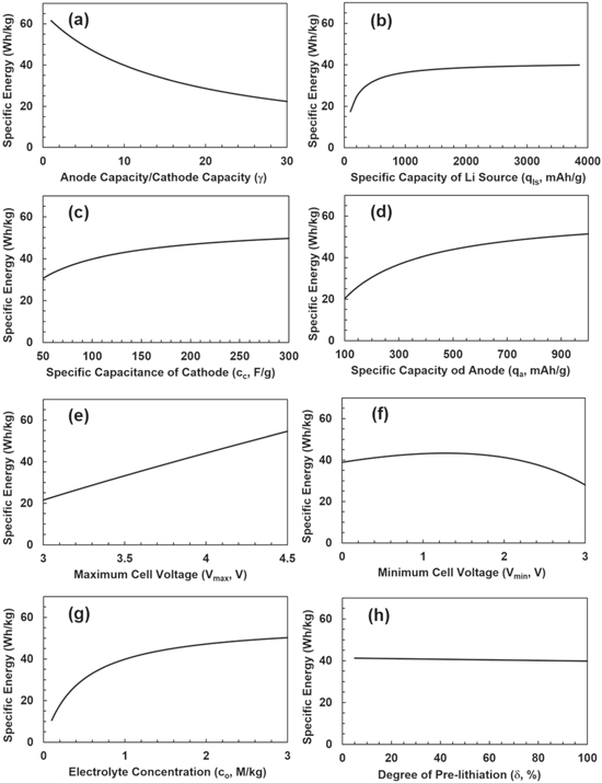
Figure 2. The specific energy of LICs based on 'active' materials as functions of (a) capacity ratio (γ), (b) specific capacity of Li source: (qls), (c) specific capacitance of cathode (cc), (d) specific capacity of anode (qa), (e) the maximum cell voltage (Vmax), (f) the minimum cell voltage (Vmin), (g) the salt concentration of electrolyte (co), and (h) the degree of pre-lithiation (δ), respectively. β = 1 and Vc-PZC = 3,0 V vs Li/Li+ are used.
Download figure:
Standard image High-resolution imageSpecific Energy of Practical LICs
For a practical LIC cell, the total electrolyte in the LIC cell is determined by the pore volumes of the two electrodes and the Li source; therefore, the porosity of the electrode always plays an important role in determining the specific energy or energy density of the cell. If we assume that 
 and
and  are volumes of cathode, anode, and Li source in a LIC, respectively, and

 and
and  are mass densities of cathode, anode, Li source, and electrolyte, respectively, then their weights can be expressed as:


where,  is the total weight of electrolyte in cathode, anode, and Li source;
 and
and  are porosities of cathode, anode, and Li source, respectively. The specific energy of a LIC with porous electrodes is:
The denominator of Eq. 14 has three terms which are cathode, anode, and Li source dependent, respectively, all with the absorbed electrolyte, and the second term in the brackets of each these is the ratio of electrolyte. We define a porosity mass density dependent parameter as  where subscript i can be c, a, and ls to represent cathode, anode, and Li source, respectively. This parameter, Pi
describes the weight ratio of electrolyte to electrode or electrolyte to Li source. The specific energy can then be expressed as:
where subscript i can be c, a, and ls to represent cathode, anode, and Li source, respectively. This parameter, Pi
describes the weight ratio of electrolyte to electrode or electrolyte to Li source. The specific energy can then be expressed as:
where,  is the weight ratio of total electrolyte to cathode, and is determined by the porosities of electrodes and Li source. In the denominator, the 1st term has been normalized by the weight of cathode, the 2nd term represents weight ratio of anode to cathode, the 3rd term represents the pre-lithiation, and the 4th term represents the electrolyte filled up pore volumes of two electrodes and Li source. Figure 3 shows comparison of three LIC cells made with minimum amount of electrolyte (theoretical specific energy), graphite and hard carbon anode with different capacity ratios of anode to cathode. For theoretical specific energy, we use graphite as the anode. For practical LIC cells, we use the electrode porosity as close as possible to the actual electrode materials such as αc
= 70% for activated carbon cathode, αa
= 20% for graphite anode, and αa
= 50% for hard carbon cathode.
31
It can be seen that the capacity ratio of anode to cathode plays an important role in determining the specific energy of LICs. Potentially, the specific energy of LICs can almost be doubled if the anode has the similar rate capability and cycle life as the EDLC cathode.
is the weight ratio of total electrolyte to cathode, and is determined by the porosities of electrodes and Li source. In the denominator, the 1st term has been normalized by the weight of cathode, the 2nd term represents weight ratio of anode to cathode, the 3rd term represents the pre-lithiation, and the 4th term represents the electrolyte filled up pore volumes of two electrodes and Li source. Figure 3 shows comparison of three LIC cells made with minimum amount of electrolyte (theoretical specific energy), graphite and hard carbon anode with different capacity ratios of anode to cathode. For theoretical specific energy, we use graphite as the anode. For practical LIC cells, we use the electrode porosity as close as possible to the actual electrode materials such as αc
= 70% for activated carbon cathode, αa
= 20% for graphite anode, and αa
= 50% for hard carbon cathode.
31
It can be seen that the capacity ratio of anode to cathode plays an important role in determining the specific energy of LICs. Potentially, the specific energy of LICs can almost be doubled if the anode has the similar rate capability and cycle life as the EDLC cathode.

Figure 3. The specific energy as a function of capacity ratio of anode to cathode based on electrode materials, Li source, and electrolyte at maximum theoretical value with minimum amount of electrolyte and practical cells with graphite and hard carbon anodes.
Download figure:
Standard image High-resolution imageComparing the specific energy (Eq. 6) and practical specific energy (Eq. 15), the difference is the weight of electrolyte. In Eq. 6,  is determined by the capacity of cathode as described by Eq. 5, but in Eq. 15, it should also be noted that the minimum value of
  is
is  (or
(or  ) in order to avoid the depletion of the electrolyte, which will cause a rapid increase in resistance such as:

The cathode, anode, and Li source can have different porosities as embedded in three Pi parameters; however, if we simplify the Eq. 16 by assuming that als = 0 for Li metal and ac = aa ; then the minimum porosity of electrodes is:

As a completely packaged LIC cell, in addition to two electrodes, Li source, and electrolyte, weights of other materials must also be accounted for. These weights come from separators soaked with electrolyte, current collectors, electrical tabs, and package materials. Due to the uncertainty of the relative ratio of the weight of above individual materials to the electrode materials, which further depends on shape of LIC cells, electrode thickness, and electrode production processes, etc.; therefore, we cannot accurately express the impact of each material weight on the specific energy, but generally described as the gravimetric package efficiency ( ), which is defined as the weight ratio of the "active" materials to the entire cell; therefore, the specific energy based on the entire cell is:

The typical value of  for commercial pouch LICs is about 50–70%.
32,33
for commercial pouch LICs is about 50–70%.
32,33
Theoretical Energy Density
The energy density is based on volumes of two electrodes and Li source, which have different porosities. If we separate electrolyte volume in each electrode and Li source and define the parameters 

 and
and  as the volumes of solid cathode material, solid anode material, solid Li source material, and liquid electrolyte, respectively, the relationship between these volumes and masses are:


Using the definition of weight ratios of Eqs. 2, 4 and 5, the theoretical energy density can be obtained as:
Energy density for practical LICs
The energy density based on the cell volume can be derived using the relationship between volume and weight of electrodes and Li source described in Eqs. 10–12, and can be expressed as:
Again, the denominator is the sum of four terms, in which, the 1st term represents cathode, the 2nd term represents anode, and the 3rd term represents the pre-lithiation. If we define a porosity mass density dependent parameter as:  where, the subscript i can be c, a, and ls to represent cathode, anode, and Li source, respectively, it actually describes the occupied volume of electrode or Li source per unit weight. Then the energy density can be expressed as:

The energy density of packaged LIC cell is:

where,  is the volumetric package efficiency.
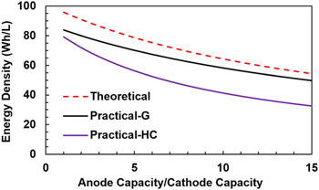
Figure 4 shows comparisons of the theoretical maximum energy density for LICs made with minimum amount of electrolyte (using Eq. 23) to the energy density for practical LICs made with graphite and hard carbon anodes (using Eq. 25). The porosity of graphite and hard carbon are 20% and 50%, respectively. 30 Again, it can be seen that the capacity ratio of anode to cathode plays a very important role in determining the energy density of LICs.
Figure 4. The energy density as a function capacity ratio of anode to cathode based on electrode materials, Li source, and electrolyte at maximum theoretical value with minimum amount of electrolyte and practical cells with graphite and hard carbon anodes.
Download figure:
Standard image High-resolution image
Pre-Lithiation with Gas Release
It should be pointed out that except of Li metal, most Li sources will release gases during the pre-lithiation process.
34,35
If so, the total weight of Li source ( ) can be divided into three parts after pre-lithiation as:

where, 
 and
and  are the weights of delithiated Li, the remaining part (dead materials), and vaporized materials from the Li source, respectively, after pre-lithiation. The weight ratio of Li source to cathode after pre-lithiation is:

Then, the formulas of specific energy (Eqs. 6 and 15) and energy density (Eqs. 23 and 25) should be modified as:


Conclusions
LICs are the only type of devices that are comparable to EDLCs in power density and cycle life, however, LICs have much higher energy density. The LIC has two unique characteristics that the capacity of anode is several times greater than that of cathode and the anode must go through a pre-lithiation process. We derived a series of formulas for the specific energy and energy density of this special energy storage device, and describe the relationship between specific energy/energy density and various parameters, especially the capacity ratio of the anode to the cathode. The equations we derived include the maximum theoretical specific energy and energy density, which are defined by the minimum amount of electrolyte in the LIC cell to match the requirement of ions from the electrolyte during the charge; and practical specific energy and energy density based on actual porosities of two electrodes and extra Li source for pre-lithiation.
Through simulation results, we can see that the most effective way to increase the specific energy and energy density of LICs, in addition to seeking to increase the specific capacity of activated carbon and improve the electrochemical stability at high potential between the activated carbon and the electrolyte for increasing the maximum cell voltage, is to find anode materials that have higher rate capability and long cycle life, which will reduce the capacity ratio of the anode to cathode; therefore, increases the specific energy and energy density of LICs. Potentially, the specific energy and energy density of LICs can be almost doubled if the anode has the similar rate capability and lifecycle as the cathode.
Acknowledgments
The work is supported by National Science Foundation grant no. 2128488.